
summa hydraulic pump free sample

Learn about the range of hydraulic pumps and motors available and how they work. Understand where and why they are used and how to get the best performance from them.
This module introduces people to the range of hydraulic pump types and discusses some of the reasons why they are used in particular applications.Recognising the different types of hydraulic pumps.
This module provides a brief introduction to the use of gerotor pumps in the fluid power industry, even though this relatively infrequent.What gerotor pumps are used for?
This module looks at the basic operation and application of both internal an external gear pumps before reviewing more detailed installation, application, and maintenance advice.What gear pumps are used for?
This module looks at the basic operation and application of both fixed and variable displacement vane pumps before reviewing more detailed installation, application, and maintenance advice.What hydraulic vane pumps are used for?
This module looks at the basic operation and application of both fixed and variable displacement piston pumps before reviewing more detailed installation, application, and maintenance advice.
This module looks at the basic operation and application of both fixed and variable displacement piston pumps before reviewing more detailed installation, application, and maintenance advice.What hydraulic radial piston pumps are used for?
This module looks at the basic operation and application of both fixed and variable displacement low speed high torque LSHT piston motors before reviewing more detailed installation, application, and maintenance advice.What hydraulic LSHT motors are used for?
This module reviews the main types of control used on variable displacement pumps. We discuss their design, operation and uses for:Two position switching pump control

A gear pump is a type of positive displacement (PD) pump. It moves a fluid by repeatedly enclosing a fixed volume using interlocking cogs or gears, transferring it mechanically using a cyclic pumping action. It delivers a smooth pulse-free flow proportional to the rotational speed of its gears.
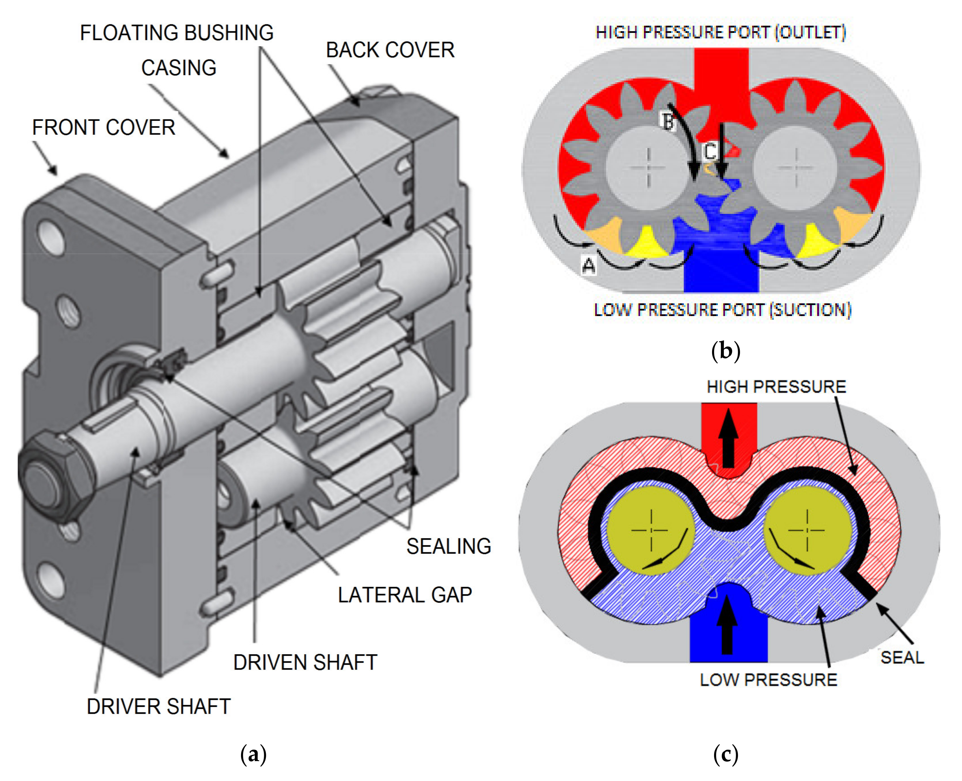
Gear pumps use the actions of rotating cogs or gears to transfer fluids. The rotating element develops a liquid seal with the pump casing and creates suction at the pump inlet. Fluid, drawn into the pump, is enclosed within the cavities of its rotating gears and transferred to the discharge. There are two basic designs of gear pump: external and internal(Figure 1).
An external gear pump consists of two identical, interlocking gears supported by separate shafts. Generally, one gear is driven by a motor and this drives the other gear (the idler). In some cases, both shafts may be driven by motors. The shafts are supported by bearings on each side of the casing.
As the gears come out of mesh on the inlet side of the pump, they create an expanded volume. Liquid flows into the cavities and is trapped by the gear teeth as the gears continue to rotate against the pump casing.
No fluid is transferred back through the centre, between the gears, because they are interlocked. Close tolerances between the gears and the casing allow the pump to develop suction at the inlet and prevent fluid from leaking back from the discharge side (although leakage is more likely with low viscosity liquids).
An internal gear pump operates on the same principle but the two interlocking gears are of different sizes with one rotating inside the other. The larger gear (the rotor) is an internal gear i.e. it has the teeth projecting on the inside. Within this is a smaller external gear (the idler –only the rotor is driven) mounted off-centre. This is designed to interlock with the rotor such that the gear teeth engage at one point. A pinion and bushing attached to the pump casing holds the idler in position. A fixed crescent-shaped partition or spacer fills the void created by the off-centre mounting position of the idler and acts as a seal between the inlet and outlet ports.
As the gears come out of mesh on the inlet side of the pump, they create an expanded volume. Liquid flows into the cavities and is trapped by the gear teeth as the gears continue to rotate against the pump casing and partition.
Gear pumps are compact and simple with a limited number of moving parts. They are unable to match the pressure generated by reciprocating pumps or the flow rates of centrifugal pumps but offer higher pressures and throughputs than vane or lobe pumps. Gear pumps are particularly suited for pumping oils and other high viscosity fluids.
Of the two designs, external gear pumps are capable of sustaining higher pressures (up to 3000 psi) and flow rates because of the more rigid shaft support and closer tolerances. Internal gear pumps have better suction capabilities and are suited to high viscosity fluids, although they have a useful operating range from 1cP to over 1,000,000cP. Since output is directly proportional to rotational speed, gear pumps are commonly used for metering and blending operations. Gear pumps can be engineered to handle aggressive liquids. While they are commonly made from cast iron or stainless steel, new alloys and composites allow the pumps to handle corrosive liquids such as sulphuric acid, sodium hypochlorite, ferric chloride and sodium hydroxide.
External gear pumps can also be used in hydraulic power applications, typically in vehicles, lifting machinery and mobile plant equipment. Driving a gear pump in reverse, using oil pumped from elsewhere in a system (normally by a tandem pump in the engine), creates a hydraulic motor. This is particularly useful to provide power in areas where electrical equipment is bulky, costly or inconvenient. Tractors, for example, rely on engine-driven external gear pumps to power their services.
Gear pumps are self-priming and can dry-lift although their priming characteristics improve if the gears are wetted. The gears need to be lubricated by the pumped fluid and should not be run dry for prolonged periods. Some gear pump designs can be run in either direction so the same pump can be used to load and unload a vessel, for example.
The close tolerances between the gears and casing mean that these types of pump are susceptible to wear particularly when used with abrasive fluids or feeds containing entrained solids. However, some designs of gear pumps, particularly internal variants, allow the handling of solids. External gear pumps have four bearings in the pumped medium, and tight tolerances, so are less suited to handling abrasive fluids. Internal gear pumps are more robust having only one bearing (sometimes two) running in the fluid. A gear pump should always have a strainer installed on the suction side to protect it from large, potentially damaging, solids.
Generally, if the pump is expected to handle abrasive solids it is advisable to select a pump with a higher capacity so it can be operated at lower speeds to reduce wear. However, it should be borne in mind that the volumetric efficiency of a gear pump is reduced at lower speeds and flow rates. A gear pump should not be operated too far from its recommended speed.
For high temperature applications, it is important to ensure that the operating temperature range is compatible with the pump specification. Thermal expansion of the casing and gears reduces clearances within a pump and this can also lead to increased wear, and in extreme cases, pump failure.
Despite the best precautions, gear pumps generally succumb to wear of the gears, casing and bearings over time. As clearances increase, there is a gradual reduction in efficiency and increase in flow slip: leakage of the pumped fluid from the discharge back to the suction side. Flow slip is proportional to the cube of the clearance between the cog teeth and casing so, in practice, wear has a small effect until a critical point is reached, from which performance degrades rapidly.
Gear pumps continue to pump against a back pressure and, if subjected to a downstream blockage will continue to pressurise the system until the pump, pipework or other equipment fails. Although most gear pumps are equipped with relief valves for this reason, it is always advisable to fit relief valves elsewhere in the system to protect downstream equipment.
Internal gear pumps, operating at low speed, are generally preferred for shear-sensitive liquids such as foodstuffs, paint and soaps. The higher speeds and lower clearances of external gear designs make them unsuitable for these applications. Internal gear pumps are also preferred when hygiene is important because of their mechanical simplicity and the fact that they are easy to strip down, clean and reassemble.
Gear pumps are commonly used for pumping high viscosity fluids such as oil, paints, resins or foodstuffs. They are preferred in any application where accurate dosing or high pressure output is required. The output of a gear pump is not greatly affected by pressure so they also tend to be preferred in any situation where the supply is irregular.
A gear pump moves a fluid by repeatedly enclosing a fixed volume within interlocking cogs or gears, transferring it mechanically to deliver a smooth pulse-free flow proportional to the rotational speed of its gears. There are two basic types: external and internal. An external gear pump consists of two identical, interlocking gears supported by separate shafts. An internal gear pump has two interlocking gears of different sizes with one rotating inside the other.
Gear pumps are commonly used for pumping high viscosity fluids such as oil, paints, resins or foodstuffs. They are also preferred in applications where accurate dosing or high pressure output is required. External gear pumps are capable of sustaining higher pressures (up to 7500 psi) whereas internal gear pumps have better suction capabilities and are more suited to high viscosity and shear-sensitive fluids.

A gear pump is a type of positive displacement (PD) pump. Gear pumps use the actions of rotating cogs or gears to transfer fluids. The rotating gears develop a liquid seal with the pump casing and create a vacuum at the pump inlet. Fluid, drawn into the pump, is enclosed within the cavities of the rotating gears and transferred to the discharge. A gear pump delivers a smooth pulse-free flow proportional to the rotational speed of its gears.
There are two basic designs of gear pump: internal and external (Figure 1). An internal gear pump has two interlocking gears of different sizes with one rotating inside the other. An external gear pump consists of two identical, interlocking gears supported by separate shafts. Generally, one gear is driven by a motor and this drives the other gear (the idler). In some cases, both shafts may be driven by motors. The shafts are supported by bearings on each side of the casing.
As the gears come out of mesh on the inlet side of the pump, they create an expanded volume. Liquid flows into the cavities and is trapped by the gear teeth as the gears continue to rotate against the pump casing.
No fluid is transferred back through the centre, between the gears, because they are interlocked. Close tolerances between the gears and the casing allow the pump to develop suction at the inlet and prevent fluid from leaking back from the discharge side (although leakage is more likely with low viscosity liquids).
External gear pump designs can utilise spur, helical or herringbone gears (Figure 3). A helical gear design can reduce pump noise and vibration because the teeth engage and disengage gradually throughout the rotation. However, it is important to balance axial forces resulting from the helical gear teeth and this can be achieved by mounting two sets of ‘mirrored’ helical gears together or by using a v-shaped, herringbone pattern. With this design, the axial forces produced by each half of the gear cancel out. Spur gears have the advantage that they can be run at very high speed and are easier to manufacture.
Gear pumps are compact and simple with a limited number of moving parts. They are unable to match the pressure generated by reciprocating pumps or the flow rates of centrifugal pumps but offer higher pressures and throughputs than vane or lobe pumps. External gear pumps are particularly suited for pumping water, polymers, fuels and chemical additives. Small external gear pumps usually operate at up to 3500 rpm and larger models, with helical or herringbone gears, can operate at speeds up to 700 rpm. External gear pumps have close tolerances and shaft support on both sides of the gears. This allows them to run at up to 7250 psi (500 bar), making them well suited for use in hydraulic power applications.
Since output is directly proportional to speed and is a smooth pulse-free flow, external gear pumps are commonly used for metering and blending operations as the metering is continuous and the output is easy to monitor. The low internal volume provides for a reliable measure of liquid passing through a pump and hence accurate flow control. They are also used extensively in engines and gearboxes to circulate lubrication oil. External gear pumps can also be used in hydraulic power applications, typically in vehicles, lifting machinery and mobile plant equipment. Driving a gear pump in reverse, using oil pumped from elsewhere in a system (normally by a tandem pump in the engine), creates a motor. This is particularly useful to provide power in areas where electrical equipment is bulky, costly or inconvenient. Tractors, for example, rely on engine-driven external gear pumps to power their services.
External gear pumps can be engineered to handle aggressive liquids. While they are commonly made from cast iron or stainless steel, new alloys and composites allow the pumps to handle corrosive liquids such as sulphuric acid, sodium hypochlorite, ferric chloride and sodium hydroxide.
External gear pumps are self-priming and can dry-lift although their priming characteristics improve if the gears are wetted. The gears need to be lubricated by the pumped fluid and should not be run dry for prolonged periods. Some gear pump designs can be run in either direction so the same pump can be used to load and unload a vessel, for example.
The close tolerances between the gears and casing mean that these types of pump are susceptible to wear particularly when used with abrasive fluids or feeds containing entrained solids. External gear pumps have four bearings in the pumped medium, and tight tolerances, so are less suited to handling abrasive fluids. For these applications, internal gear pumps are more robust having only one bearing (sometimes two) running in the fluid. A gear pump should always have a strainer installed on the suction side to protect it from large, potentially damaging, solids.
Generally, if the pump is expected to handle abrasive solids it is advisable to select a pump with a higher capacity so it can be operated at lower speeds to reduce wear. However, it should be borne in mind that the volumetric efficiency of a gear pump is reduced at lower speeds and flow rates. A gear pump should not be operated too far from its recommended speed.
For high temperature applications, it is important to ensure that the operating temperature range is compatible with the pump specification. Thermal expansion of the casing and gears reduces clearances within a pump and this can also lead to increased wear, and in extreme cases, pump failure.
Despite the best precautions, gear pumps generally succumb to wear of the gears, casing and bearings over time. As clearances increase, there is a gradual reduction in efficiency and increase in flow slip: leakage of the pumped fluid from the discharge back to the suction side. Flow slip is proportional to the cube of the clearances between the cog teeth and casing so, in practice, wear has a small effect until a critical point is reached, from which performance degrades rapidly.
Gear pumps continue to pump against a back pressure and, if subjected to a downstream blockage will continue to pressurise the system until the pump, pipework or other equipment fails. Although most gear pumps are equipped with relief valves for this reason, it is always advisable to fit relief valves elsewhere in the system to protect downstream equipment.
The high speeds and tight clearances of external gear pumps make them unsuitable for shear-sensitive liquids such as foodstuffs, paint and soaps. Internal gear pumps, operating at lower speed, are generally preferred for these applications.
External gear pumps are commonly used for pumping water, light oils, chemical additives, resins or solvents. They are preferred in any application where accurate dosing is required such as fuels, polymers or chemical additives. The output of a gear pump is not greatly affected by pressure so they also tend to be preferred in any situation where the supply is irregular.
An external gear pump moves a fluid by repeatedly enclosing a fixed volume within interlocking gears, transferring it mechanically to deliver a smooth pulse-free flow proportional to the rotational speed of its gears.
External gear pumps are commonly used for pumping water, light oils, chemical additives, resins or solvents. They are preferred in applications where accurate dosing or high pressure output is required. External gear pumps are capable of sustaining high pressures. The tight tolerances, multiple bearings and high speed operation make them less suited to high viscosity fluids or any abrasive medium or feed with entrained solids.

This article aims to describe the main features of the vane pump technology, how it works, its advantages and disadvantages, and where it is most commonly used. Finally, we will briefly mention the Fluid-o-Tech vane pumps.
Rotary vane pumps are a type of positive displacement pump. Like all positive displacement pumps, the flow rate is always directly proportional to the speed.
Vane pumps are available with different types of vane: sliding, flexible, oscillating, rotating, and external vanes. The vane pumps are known for their dry-priming, easy maintenance, and good suction characteristics throughout the life of the pump.
A splined rotor is supported eccentrically in a cycloidal cam. The rotor sits close to the cam wall to form a crescent-shaped cavity. The rotor is sealed in the cam by two side plates. The vanes or blades fit into the rotor cavities. When the rotor rotates and fluid enters the pump, the centrifugal force, the hydraulic pressure, and/or the pushrods push the vanes towards the housing walls. The tight seal between the vanes, the rotor, the cam, and the side plate makes this technology powerful for good suction, which is common to the vane pumping principle.
The housing and cam force the fluid into the pumping chamber through holes in the cam (small red arrow on the bottom of the pump). The fluid enters the pockets created by the vanes, the rotor, the cam, and the side plate.
The rotary vane pump is very versatile and can be used in a variety of sectors and applications, from dosing to transferring and repressurizing fluids. Depending on the choice of materials, rotary vane pumps can handle a wide range of clean fluids.
Fluid-o-Tech is able to supply a wide range of rotary vane pumps covering a variety of applications in different sectors. In stainless steel, low-lead brass, technopolymer, direct coupled, magnetic or electromagnetic drive at variable speed, our pumps cover a flow rate range from 30 to 2200 l/h at pressures up to 18 bar. The built-in safety valve, available on request, limits the pressure to protect the pump and the hydraulic circuit.
The Fluid-o-Tech rotary vane pumps, WRAS or NSF certified for use with potable water, are the reference choice in the market of espresso machines and beverage dispensers for professional use.

The best method of acquiring an oil sample is to utilize apump (pictured above) that attaches to a test point in the return line. This ensures the oil being tested is in the work stream and accurately represents the oil going through your system.
3. Purge the Test Line - Use the pump to ensure that all of the oil from the last oil sample is out of the test line before filling up your sample bottle.
9. Fill Out the Paperwork - Make sure to give as much detail on these forms as possible so the lab knows what it"s dealing with during testing. Things like the valves incorporated and pumps running can make a big difference when analyzing the test findings and troubleshooting any issues.
If you want assistance in taking or analyzing oil samples for your hydraulic systems, we have industry experts that would be happy to help and answer your questions!

Companies: 10+ – Including Bailey International LLC, Bosch Rexroth AG, Bucher Hydraulics GmbH, CASAPPA SpA, Caterpillar Inc., Dalian engineering, Danfoss AS, Dynamatic Technologies Ltd., Eaton Corp. Plc, Enerpac Tool Group Corp., HYDAC Verwaltung GmbH, Kawasaki Heavy Industries Ltd., Linde Hydraulics GmbH and Co. KG, Mitsubishi Heavy Industries Ltd., Oilgear, Parker Hannifin Corp., Permco Inc., Salami SpA, Tuthill Corp., and Daikin Industries Ltd. among others
Companies profiledBailey International LLC, Bosch Rexroth AG, Bucher Hydraulics GmbH, CASAPPA SpA, Caterpillar Inc., Dalian engineering, Danfoss AS, Dynamatic Technologies Ltd., Eaton Corp. Plc, Enerpac Tool Group Corp., HYDAC Verwaltung GmbH, Kawasaki Heavy Industries Ltd., Linde Hydraulics GmbH and Co. KG, Mitsubishi Heavy Industries Ltd., Oilgear, Parker Hannifin Corp., Permco Inc., Salami SpA, Tuthill Corp., and Daikin Industries Ltd.
The hydraulic pumps market is fragmented and the vendors are deploying growth strategies such as increasing their market presence through mergers and acquisitions, and expansion activities to compete in the market.
Story continuesBailey International LLC- The company offers hydraulic pumps such as chief two stage pump 11 gpm and chief two stage pump 16 gpm. Moreover, it is a privately held company headquartered in the US. It is a global company, with limited information regarding its financials and limited information regarding its employee strength is available. Its revenue from the global hydraulic pumps market contributes to its overall revenues along with its other offerings, but it is not a key revenue stream for the company.
55% of the market"s growth will originate from APAC during the forecast period. China and Japan are the key markets for hydraulic pumps in APAC. Market growth in this region will be faster than the growth of the market in the European, North American, and South American regions.
The rapid urbanization and the need to improve connectivity between different regions will facilitate the hydraulic pumps market growth in APAC over the forecast period.
Hydraulic pumps are extensively used in the oil and gas sector. They are used as an alternative to gas lift systems and electric submersible pumps (ESPs). Hydraulic pumps are also favored and used where high flow rates are required, such as in wells having a heavy concentration of sand or other solids from frac operations, as they can handle high gas volumes. The global oil and gas industry is presently undergoing significant expansion and is a primary driver for the growth of the global hydraulic pumps market. There are a lot of factors leading to the expansion of the global oil and gas industry. The demand for oil and natural gas is increasing steadily due to improvements in global economic growth. The global consumption of natural gas exhibited a significant rise due to the increasing adoption of natural gas as a fuel in the last decade. Also, with the rise in fuel consumption from developing economies such as China and India, the demand for natural gas is expected to grow significantly during the forecast period. The rise in investments in E and P activities will increase the demand for hydraulic pumps. These factors will thus drive the growth of the global hydraulic pumps market during the forecast period.Hydraulic Pumps Market Trend:
Hydraulic fluids, including lubricants, perform various functions, including protection against corrosion and wear, transferring contaminants to filters, and dissipating heat from hot zones. However, under certain conditions, these lubricants become flammable. Furthermore, there is a risk of small leaks when lubricants are pressurized in hydraulic lines. The hydraulic system becomes more susceptible to fire due to these leaks. One of the important parameters to consider in selecting the appropriate hydraulic fluid is the operating temperature, which can determine the degree of fire protection required. Some of the industrial applications of FRHFs include mining, die-casting, offshore applications, power generation, iron, and steel industry, among others. They do not readily ignite when sprayed under pressure. Besides providing lubrication and being non-corrosive, glycol fluids are more cost-effective than other hydraulic fluids. Utilizing FRHFs can not only ensure the safe operation of the hydraulic pumps but may even reduce the need for a fire-suppression system. Thus, end-users can prevent and minimize the risks of any fire-related losses by replacing the flammable hydraulic oils with fire-resistant fluids in the hydraulic systems. Such trends can have a positive impact on the growth of the market during the forecast period.
Pump Jack Market by Application and Geography - Forecast and Analysis 2022-2026:The pump jack market share is expected to increase by USD 987.08 million from 2021 to 2026, and the market"s growth momentum will decelerate at a CAGR of 4.78%. To get more exclusive research insights:
Hydraulic Dosing Pump Market by End-user and Geography - Forecast and Analysis 2022-2026:The hydraulic dosing pump market share is expected to increase by USD 247.98 million from 2021 to 2026, and the market"s growth momentum will accelerate at a CAGR of 5.59%. To get more exclusive research insights:
4 Five Forces Analysis4.1 Five forces summary4.2 Bargaining power of buyers4.3 Bargaining power of suppliers4.4 Threat of new entrants4.5 Threat of substitutes4.6 Threat of rivalry4.7 Market condition
10 Vendor Analysis10.1 Vendors covered10.2 Market positioning of vendors10.3 Bailey International LLC10.4 Bosch Rexroth AG10.5 Bucher Hydraulics GmbH10.6 CASAPPA SpA10.7 Danfoss AS10.8 Eaton Corp. Plc10.9 Enerpac Tool Group Corp.10.10 Kawasaki Heavy Industries Ltd.10.11 Mitsubishi Heavy Industries Ltd.10.12 Parker Hannifin Corp.

Hydraulic valves are mechanical devices that are used to regulate the flow of fluid within a hydraulic circuit or system. They can be used to completely close a line, to redirect pressurized fluid or to control the level of flow to a certain area. Designed in a wide range of styles, these valves can be controlled manually or automatically, by physical, mechanical, pneumatic, hydraulic, or electrical activation. Hydraulic valves must be capable of withstanding large amounts of fluid pressure, as the nature of many hydraulic systems will entail high pressures upwards of 3,000 psi or more. For this reason, they are often constructed of steel, iron, or other metals that have enough strength to withstand continuous operation under pressurized conditions.
This article will present information about hydraulic valves, including the different types, their construction, and pertinent specifications. To learn more about other types of valves, see our related guide Understanding Valves.
Hydraulic valves are available in a wide variety of styles including many that are common to other types of valves, such as ball, butterfly, bypass relief, check, needle, diverter, regulating, pilot-operated, proportional and directional. From a broad perspective, these hydraulic valves may be characterized as being of three primary types which are:
Hydraulic pressure control valves are used to regulate the fluid pressure that is passing through hydraulic systems to maintain that pressure at desired levels as determined by the system operator. Fluid systems are typically designed for operation at a set range of pressures. These types of valves serve a key role to prevent rises in pressure that may result in leaks of hydraulic fluid or the bursting of pipes and tubing. They are also used to maintain a set pressure in a part of a hydraulic circuit.
The various types of pressure control valves used in hydraulic systems include relief valves, reducing valves, sequence valves, counterbalance valves, and unloading valves.
Hydraulic flow control valves are used to adjust the flow rate of hydraulic fluid in a hydraulic system. These valves have a port that is able to be adjusted so that the flow area may be changed to provide an alteration in the flow rate through the valve. An example of how this type of hydraulic valve would be used is in control circuits for devices such as cylinders, motors, or actuators. The speed of motion of these devices is a direct function of flow rate – reducing the flow rate reduces the speed of their operation and vice versa.
The different types of hydraulic flow control valves include fixed flow control valves, adjustable flow control valves, throttling flow control valves, and pressure compensated flow control valves. The mechanism for flow control within these valves will vary based on the mechanical design of the valve, which usually is one of the familiar valve styles common to other valves, namely:
Hydraulic directional control valves are used to route hydraulic fluid in a circuit or system to various devices as needed. They shift between discrete positions such as extend, retract, or neutral position for controlling a hydraulic cylinder, for example. They are also capable of shifting into intermediate states wherein they can be used to control the speed, direction, or acceleration of an actuator.
A simple form of discrete hydraulic directional control valve is a binary valve, which either blocks or passes fluid flow. Check valves are an example and use a plunger, ball, or poppet to seal against a seat when fluid attempts to pass in the opposite direction of flow from what is desired.
More complex hydraulic directional control valves may have multiple ports as by their nature they shift fluid between these different valve ports to feed hydraulic devices. As a result, they are characterized by a standardized numbering system that consists of two numerical values such as 2/2 or 4/3. The first number in this system identifies the number of fluid ports that the valve contains, and the second number indicates the number of valves states or positions that the valve can achieve. (Note - in the U.S., the number of ports is sometimes also known as the number of ways.) So with this convention, 2/2 represents a two-port valve that has two positions, and 4/3 represents a four-port valve that has three positions. In the latter example of a 4/3 valve that might be used to control a hydraulic cylinder, the three positions would represent:
Many hydraulic directional control valves make use of spools that slide between passages allowing fluid to flow through open ports, depending on the position of the spool in the valve body. Valves may use single or multiple spools to accomplish the desired port control. Other flow control elements in these valves may be plungers or poppets.
The valve component that moves these flow control elements is known as the valve operator or actuator. These devices provide for the proper sequencing and timing of the valve position changes that are needed to control the hydraulic circuit or systems. Options for the type of actuator mechanism include mechanical actuation, pilot actuation, or electrical/electronic actuation.
Electrical/electronic actuation involves the use of solenoids that convert electrical signals in the form of a current supplied to the solenoid coil into the mechanical movement of a plunger that can generate either linear or rotary displacement. Electrical solenoids are limited as to the amount of force that can be generated, and so switching high-pressure hydraulic circuits by direct action is not possible. Combining solenoid use with pilot actuation allows the solenoid to switch lower pressure pilot circuits that can then be used to control higher pressure ports. More on this concept is available in our related guide on solenoid valves.
Hydraulic valves are specified using several parameters that relate to their size, flow capacity, connections, and actuation mechanism. The typical specifications for these valves are outlined below but recognize that there can be variations in these parameters among different valve manufacturers and suppliers, and so differences in representation may exist from supplier to supplier. The data presented below should serve as a general indicator of what needs to be considered when looking to specify a hydraulic valve.
Valve type – refers to the specific hydraulic valve type needed, which may reflect the physical style (ball, check, needle, etc.) or may refer to the control being sought (flow control, pressure control, or directional control).
This article presented a summary of information about hydraulic valves, including what they are, the different types, and key specifications. For information on other topics, consult our additional guides or visit the Thomas Supplier Discovery Platform where you can locate potential sources of supply for over 70,000 different product and service categories.
The aim is to secure a device that will not only pump water, but also automatically lift water from a reservoir or feed point it (river/stream, lake/pond, etc.) to great heights.
The self-acting ram pump was in invented in 1796 by Joseph Michel Montgolfier. The mechanism is not a costly one and requires little maintenance, making it especially suitable for use in mountainous areas, for sheep pens, for example, or for villages that are located high above water points.
The main strong points of hydraulic ram pumps are their limited need for maintenance and the absence of any motor related costs as the power used to operate the ram comes from water falling. This makes it possible to avoid the problem faced by suction pumps that see the height they can lift water by reduced with altitude. In this approach, raised locations that cannot be fed by gravitation alone (sloped pipes through which the water fall naturally with the slope) and it offers an alternative to costly solutions based on the presence of an electric or diesel engine.
This, generally metal, part is the one that causes the water hammer effect when it closes due to the water flow pressure. It is this valve that will determine the performance of the hydraulic ram and especially the efficiency of the pump. This is why, it is a good idea that it be installed by a qualified technician.
The pump body receives water from the water supply source via the drive pipe and sends it to the waste valve and the delivery check valve. The water hammer effects occur in the pump body requiring that it be made from a material able to stand up to pressure variations and any chemical attack caused by the water supply.
This valve has a specific role during each operating phase. During the overpressure phase, it is open and lets the water flow from the pump body into the pressure vessel. During the underpressure phase, it is closed and stops the tank emptying into the pump body.
It receives water during overpressure periods and forces it out again during pump body underpressure periods. The pressure vessel is essential to proper pump operation for it increases its efficiency and stops the pump body, drive pipe or even the tank itself from exploding due to the water hammer effect.
This is a small opening below the delivery check valve in the pump body used to supply the pressure vessel with the air needed to push the water out through the delivery pipe. It is only installed on the most sophisticated hydraulic ram pumps, so as to avoid the need to bleed the air tank.
The water enters the pump body at rising speed causing the waste valve (clack valve) to close under the effect of the internal pressure. Closing this valve causes an overpressure condition, opening the delivery check valve so that the water in the pump body can flow into the pressure vessel. The air in the pressure vessel is compressed.
The pressure in the pump body therefore drops and the delivery check valve closes under the pressure of the air in the pressure vessel and the weight of the water. The air compressed in the pressure vessel propels a part of the water contained in the tank back out, until the pressure of the water in the delivery pipe and the weight of the water and the atmospheric pressure all equal out again.
If the air tank is not fitted with a snifting valve but only with two cut off valves (one for letting air in and one for draining off water), then it is extremely important to stop the pump regularly to drain the air tank. This is because the air may become dissolved in the water. After a certain number of cycles, the air having become dissolved in the water and drawn off with the water pushed out, then the mechanism itself becomes vulnerable to water hammer effects.
When the pump is fitted with a snifting valve, it is important regularly check it for correct operation and to remove any dirt or debris likely to clog it.
Pump flow rate is a relatively constant one as it is necessary to avoid changing the clack valve setting. Consequently, it is common to see a number of hydraulic ram pumps installed in parallel so as to adjust the desired flow rate by adjusting the number of pumps operating.
Gravel and other debris can interfere with pump operation (causing drive pipe wear and waste valve blockages), so it is necessary to fit the drive pipe with a strainer so as to stop any impurities from entering the pump.
To avoid resonance phenomena and keep the water clear, it is important that the drive pipe be properly attached to the pump body which itself must be solidly anchored to a concrete base and high enough to ensure that the clack valve will not become submerged and that the pump can operate.
Hydraulic ram pump purchase prices are highly variable, ranging from €500 to €1,500 or even €4,000 at the top end of the scale (see Source [5]). Nevertheless, it is also possible to craft your own such pump for less cost (Sources [6] and [7]), but the service life of a homemade pump is less.
Pump maintenance can be performed regularly by its users, therefore not inducing any additional costs. However, the most fragile parts like the waste valve and the delivery check valve may require replacement if they become too worn.
A ten page document explaining how a hydraulic ram works and providing elements for choosing the right ram, calculating its efficiency and properly installing the ram.
(9) Walton. Exemples d’adductions d’eau potable par pompage béliers hydrauliques au Burundi (Examples of bringing in drinking water using hydraulic ram pumping in Burundi).

Hydraulic Pump Market was valued at US$ 9.8 Bn. in 2021. Global Hydraulic Pump Market size is estimated to grow at a CAGR of 4% over the forecast period.
From 2021 to 2029, the global hydraulic pump market is expected to grow at a CAGR of 4%, from $9.8 billion in 2021 to $12.90 billion in 2029. Hydraulic pumps transform mechanical energy into hydraulic or hydrostatic pressure. Such forces give adequate energy support for the movement to manage power at the pump channel impacted by the load. The vacuum formed at the pump entry drives the fluid from the reserve into the pump entrance line during hydraulic pump operations.
Rapid development and urbanization in important developing nations such as China and India are driving the expansion of the hydraulic pumps industry. Because of the expanding urban population, many countries are seeing fast industrialization. As a result, there has been an increase in consumer demands and products, affecting the expansion of end-use sectors.
Hydraulic pump demand has been directly impacted by the cumulative growth of end-use industries. Hydraulic pump demand is predicted to rise strongly throughout the forecast period, with a high number of manufacturing sectors being established and planned expansions taking place across industries.
Governments in emerging economies in Africa and Asia, particularly in India, China, and South Africa, are stepping up efforts to enhance drinking water availability in rural and urban regions. The demand for hydraulic pumps is expected to develop significantly in the next years as a result of increased government investments and activities.
Factory automation has progressively gained traction in recent years. Intelligent machines are being used extensively by the construction equipment industry to increase the rate of industrial output and make it more energy- and cost-efficient. They are also concentrating on lowering trash output in order to maintain the sustainability quotient. End users are adopting alternative pump solutions hydraulic gear pumps to satisfy the evolving requirements of consumers around the world, owing to their operational inefficiency when compared to more advanced counterparts available on the market. In agricultural equipment, for example, electrically operated medium pressure pumps are frequently preferred over gear pumps. Over the projected period, demand for hydraulic gear pumps is expected to be hampered by the increasing adoption of various alternative pumping solutions such as piston pumps.
Hydraulic gear pumps have long been utilized in a variety of applications due to their simple design, adaptability, and ease of operation, as well as their diversity. Hydraulic gear pumps are an excellent alternative for a variety of chemical and industrial processes because of these qualities. Furthermore, when compared to other pump types available on the market, the price of a hydraulic gear pump remains within a reasonable range.
In the construction business, hydraulic pumps, particularly gear pumps, are widely employed. The market for construction equipment is likely to be driven by the widespread use of construction equipment in operations such as excavation, earthmoving, and lifting and material handling. Manufacturers are expanding their investments in machine tools in both developed and developing countries in order to improve their production processes and systems. The building industry and hydraulic systems will benefit from the maturation of both of these areas in the coming years. The market is being propelled forward by an increase in construction activity as well as rising construction spending in various countries. According to a World Bank poll, building investment is expected to exceed $11.9 trillion by 2021.
East Asia, particularly China and Japan, will continue to be the leading consumers of hydraulic gear pumps due to the presence of several manufacturing facilities for construction equipment, material handling equipment, and construction equipment, including key players such as Mitsubishi, Hangcha Group, and Komatsu Ltd. Japan alone has a larger market share than Latin America and the Middle East and Africa combined.
The objective of the report is to present a comprehensive analysis of the global Hydraulic Pump Market to the stakeholders in the industry. The past and current status of the industry with the forecasted market size and trends are presented in the report with the analysis of complicated data in simple language. The report covers all the aspects of the industry with a dedicated study of key players that include market leaders, followers, and new entrants.
The reports also help in understanding the Hydraulic Pump Market dynamic, structure by analyzing the market segments and projecting the Hydraulic Pump Market size. Clear representation of competitive analysis of key players by Vehicle type, price, financial position, product portfolio, growth strategies, and regional presence in the Hydraulic Pump Market make the report investor’s guide.


 8613371530291