
sundstrand hydraulic pump catalogue free sample

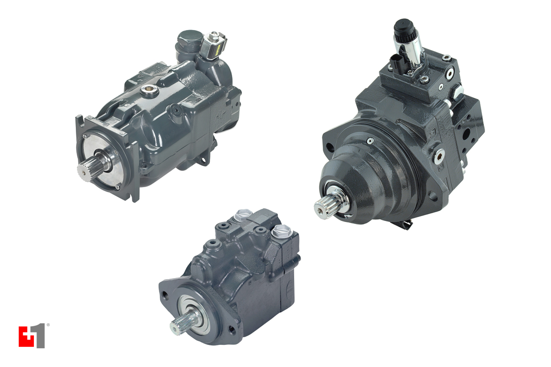
Sauer Sundstrand hydraulics is one of the largest companies in the mobile hydraulics industry. Sauer Sundstrand designs, manufactures and sells a range of hydraulic and electronic components, including hydraulic orbital motors, hydraulic piston pumps and motors, steering components and proportional valves.
Precision Fluid Power repairs and supplies remanufactured and new Sauer Sundstrand hydraulics – hydraulics pumps, hydraulics valves, and hydraulics motors. Search our online catalog or contact us and let us know how we can help you.
We can supply what you need or repair what you have. Before purchasing, there may be a good chance that your current hydraulic pump, motor, valve can be repaired. hydraulics pump repairs, including motors, valves comes with our two year warranty.
When purchasing, consider Sauer Sunstrand hydraulics remanufactured or after market hydraulic units. Best of all they can get you back up and running for less than the cost of a new hydraulic unit. Get a free quote so you can compare costs for a new, repaired or remanufactured unit. Whether you’re looking for hydraulic pump repair, hydraulic motor repair, hydraulic valve repair, or a replacement for any of your Sauer Sundstrand hydraulic units, Precision Fluid Power has what you need.
Established as Sundstrand Machine Tools in 1946 and renamed to Sundstrand Corporation thirteen years later, the company was an innovative force from its very start. This can be seen through Gunnar A. Wahlmark’s involvement from 1925 when he started out as a draftsman, going on to form several divisions of the company, including the Sundstrand Hydraulic division. After being acquired by Danfoss in 1998, becoming Danfoss-Sauer, the company evolved once again in 2000, becoming Sauer-Danfoss, eventually changing once more to be known as Danfoss Power Solutions.
However, all hydraulic unit models, including Sauer Sundstrand hydraulic motors, Sauer Sundstrand pumps, Sauer Danfoss pumps & motors, are within the purview of what we sell. No matter what Sauer, Danfoss, or Sundstrand product you need, we can repair or supply the unit you want.

Sundstrand hydraulics transmissions have been expressly designed to provide the long life and reliability required in work related applications. Extended fatigue life, minimum deflection of parts, and adequate reserve capacity to absorb shock loads are the features that keep machines on the job.
Control of the variable displacement, axial piston pump is the key to controlling the vehicle. Prime mover horsepower is transmitted to the pump. When the operator moves the control lever, the swashplate in the pump is tilted from neutral. The position of the control lever will determine the angle of the swashplate and, therefore, the volume of oil displaced by the pump. The control lever is seedless, therefore, the direction and speed of the vehicle is infinitely variable from zero to maximum.
Pumps and motors are contained in separate housings or may be connected by a common end cap. All valves required for a closed loop circuit are included in either the pump or motor assemblies. A reservoir, filter, cooler, and lines complete the circuit.
The Danfoss MP1 is the next evolution in closed circuit axial piston pumps. No matter what industry you serve, MP1 pumps offer the performance needed for today"s small- to medium-sized equipment. Another example of our commitment to the mobile hydraulic industry. You can count on us to do business at your speed. Delivering what you need, when you need it—to propel you forward.
CONSTRUCTION Pressure balanced deflecting plate One piece gear construction All D Series pump gear shafts are of one-piece construction. This enables the shaft to provide uniform high strength and accurate gear profile relative to the journals for smooth mesh operation. This design controls all gear tolerances, in particular total radial run-out of the gear and gear face parallelism. The integral gear shafts are constructed of heat-treated AISI 8620 steel manufactured to precise tolerances and surface finishes for maximum life and minimal leakage. This integral design eliminates the...
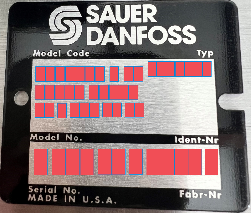
ORDER CODE Single pumpsTandem pumps B 1 2 3 1 2 C D E F H J KA ֖ ֖ ֖ ֖ > B 1 2 3 1 2 C R S D E F H J KA ֖ ֖ ֖ ֖ ֖ > Example order code for single pumpsExample order code for tandem pumps ABCDEFHJK DE1L25SHBBN104NNN000AJANNNN ABCRSDEFHJK DE2L25SHBB10425N104NNN000AXANNNN For single pumps, R and S positions are omitted. A1: Product CodeDescription DED Series, revision level E A2: Sections CodeDescription 1Single section pump 2Dual section pump A3: Rotation CodeDescription LLeft hand (counterclockwise) RRight hand (clockwise) All available options are not shown in the model code. Please contact...
ORDER CODE (continued) Single pumpsTandem pumps B 1 2 3 1 2 C D E F H J KA ֖ ֖ ֖ ֖ > B 1 2 3 1 2 C R S D E F H J KA ֖ ֖ ֖ ֖ ֖ > B1: Displacement 1 Codecm / rev [in 3 / rev] Codecmӳ / rev [in 3 / rev] 077.0 [0.43] 109.5 [0.58] 1312.6 [0.77] 1414.3 [0.87] 1717.0 [1.04] 1919.0 [1.16] 2120.5 [1.25] 2322.5 [1.37] 2525.4 [1.55] 2929.0 [1.77] 3231.8 [1.94] 3838.0 [2.32] 4141.0 [2.50] B2: Input shaft Code SCSAE 11 tooth spline, 1.50 in lengthSESAE 9 tooth spline, 1.25 in lengthSF11 tooth spline, 1.25 in length (special modified length)SHSAE 13 tooth spline, 1.62 in lengthPB22 mm (7/8 in) dia x 41...
ORDER CODE (continued) Single pumpsTandem pumps B 1 2 3 1 2 C D E F H J KA ֖ ֖ ֖ ֖ > B 1 2 3 1 2 C R S D E F H J KA ֖ ֖ ֖ ֖ ֖ > S: Rear displacement of tandem pump (omit if single pump) Codecm / rev [in 3 / rev] 077.0 [0.43] 109.5 [0.58] 1312.6 [0.77] 1414.3 [0.87] 1717.0 [1.04] 1919.0 [1.16] 2120.5 [1.25] 2322.5 [1.37] 2525.4 [1.55] 2929.0 [1.77] 3231.8 [1.94] 3838.0 [2.32] 4141.0 [2.50] D: Rear cover port options CodeLocationPort typeInlet sizeOutlet size N101RadialO-ring boss1-1/16 in7/8 in N104RadialO-ring boss1-5/16 in1-1/16 in N113RadialO-ring bossNA7/8 in N125RadialO-ring boss1-5/8...
ORDER CODE (continued) Single pumpsTandem pumps B 1 2 3 1 2 C D E F H J KA ֖ ֖ ֖ ֖ > B 1 2 3 1 2 C R S D E F H J KA ֖ ֖ ֖ ֖ ֖ > J: Nameplate CodeDescription ANStandard nameplate (do not use with N504) BNStandard label (use with rear cover code N504) K: Special features CodeDescription NNNNo special features, standard black paint All available options are not shown in the model code. Please contact your Sauer-Danfoss representative if your application requires an option not shown in the model code. 16 520L0781 Rev AC Օ October 2007 size="-3">
OPERATING PARAMETERS Definitions of the D Series operating parameters appear below. Consult Sauer-Danfoss technical support for applications running outside of these parameters. Recommended fluid velocities Line sizing Inlet conditions should be reviewed to minimize inlet oil velocity and inlet vacuums. This will result in quieter system operation, reduced operating temperatures and longer pump life. To avoid pump cavitation, the maximum inlet line flow should not exceed 4.3 m/sec (14 ft/sec). Discharge velocity should be limited to 8 m/sec (18 ft/sec). > Inlet 4.3 m/sec [14 ft/sec]...
OPERATING PARAMETERS (continued) Fluids Catalog ratings for D series gear pumps are based on operation with a premium hydraulic fluid containing oxidation, rust, and foam inhibitors. The fluid must possess good thermal and hydrolytic stability to prevent wear, erosion, and corrosion of internal components. Consult Sauer-Danfoss technical support before using non-petroleum based (including water glycol), fire-resistant, or biodegradable fluids. The use of these fluids may require special seal materials and/or specially designed hardware.For more information on hydraulic fluid selection, see...
OPERATING PARAMETERS (continued) Filtration To prevent damage to the pump, including premature wear, fluid entering the pump inlet must be free of contaminants. D series pumps require system filtration capable of maintaining fluid cleanliness at ISO 4406-1999 class 22/18/13 or better.Sauer-Danfoss does not recommend suction line filtration. Suction line filtration can cause high inlet vacuum, which limits pump operating speed. Instead we recommend a 100 micron screen in the reservoir covering the pump inlet. This protects the pump from coarse particle ingestion.Return line filtration is the...
PUMP DRIVES Pump drive D Series pumps can be direct-driven by tapered, straight keyed or splined drive. They are well suited for external gear or pulley drive. Gear drive for the pump can be by spur or helical gear.Contact Sauer-Danfoss technical support for all non-standard direct-driven and all gear-driven or pulley-driven applications. The figures on the next page show the information Sauer-Danfoss requires to analyze applications using a gear or pulley drive. From this information, Sauer-Danfoss determines: If the drive method is feasible Օ Optimum range of angles for driving the pump...

Our team of trained engineers and technicians have been remanufacturing Sauer-Danfoss® (Sauer-Sundstrand) pumps and motors for over 30 years. We specialize in the remanufacturing of nearly every Series in the Sauer-Danfoss/Sundstrand family. Many units are in stock and available for immediate delivery. Don"t see what you"re looking for? Our inventory is constantly changing, give us a call - we still might have it or can possibly source it from our other companies.
A hydraulic pump is a mechanical device that converts mechanical power into hydraulic energy. It generates flow with enough power to overcome pressure induced by the load.
A hydraulic pump performs two functions when it operates. Firstly, its mechanical action creates a vacuum at the pump inlet, subsequently allowing atmospheric pressure to force liquid from the reservoir and then pumping it through to the inlet line of the pump. Secondly, its mechanical action delivers this liquid to the pump outlet and forces it into the hydraulic system.
The three most common hydraulic pump designs are: vane pump, gear pump and radial piston pump. All are well suited to common hydraulic uses, however the piston design is recommended for higher pressures.
Most pumps used in hydraulic systems are positive-displacement pumps. This means that they displace (deliver) the same amount of liquid for each rotating cycle of the pumping element. The delivery per cycle remains almost constant, regardless of changes in pressure.
Positive-displacement pumps are grouped into fixed or variable displacement. A fixed displacement pump’s output remains constant during each pumping cycle and at a given pump speed. Altering the geometry of the displacement chamber changes the variable displacement pump’s output.
Fixed displacement pumps (or screw pumps) make little noise, so they are perfect for use in for example theatres and opera houses. Variable displacement pumps, on the other hand, are particularly well suited in circuits using hydraulic motors and where variable speeds or the ability to reverse is needed.
Applications commonly using a piston pump include: marine auxiliary power, machine tools, mobile and construction equipment, metal forming and oil field equipment.
As the name suggests, a piston pump operates through pistons that move back and forth in the cylinders connected to the hydraulic pump. A piston pump also has excellent sealing capabilities.
A hydraulic piston pump can operate at large volumetric levels thanks to low oil leakage. Some plungers require valves at the suction and pressure ports, whilst others require them with the input and output channels. Valves (and their sealing properties) at the end of the piston pumps will further enhance the performance at higher pressures.
The axial piston pump is possibly the most widely used variable displacement pump. It’s used in everything from heavy industrial to mobile applications. Different compensation techniques will continuously alter the pump’s fluid discharge per revolution. And moreover, also alter the system pressure based on load requirements, maximum pressure cut-off settings and ratio control. This implies significant power savings.
Two principles characterise the axial piston pump. Firstly the swash plate or bent axis design and secondly the system parameters. System parameters include the decision on whether or not the pump is used in an open or closed circuit.
The return line in a closed loop circuit is under constant pressure. This must be considered when designing an axial piston pump that is used in a closed loop circuit. It is also very important that a variable displacement volume pump is installed and operates alongside the axial piston pump in the systems. Axial piston pumps can interchange between a pump and a motor in some fixed displacement configurations.
The swivel angle determines the displacement volume of the bent axis pump. The pistons in the cylinder bore moves when the shaft rotates. The swash plate, in the swash plate design, sustain the turning pistons. Moreover, the angle of the swash plate decides the piston stroke.
In general, the largest displacements are approximately one litre per revolution. However if necessary, a two-litre swept volume pump can be built. Often variable-displacement pumps are used, so that the oil flow can be adjusted carefully. These pumps generally operate with a working pressure of up to 350–420 bars in continuous work
Radial piston pumps are used especially for high pressure and relatively small flows. Pressures of up to 650 bar are normal. The plungers are connected to a floating ring. A control lever moves the floating ring horizontally by a control lever and thus causes an eccentricity in the centre of rotation of the plungers. The amount of eccentricity is controlled to vary the discharge. Moreover, shifting the eccentricity to the opposite side seamlessly reverses the suction and discharge.
Radial piston pumps are the only pumps that work continuously under high pressure for long periods of time. Examples of applications include: presses, machines for processing plastic and machine tools.
A vane pump uses the back and forth movement of rectangle-shaped vanes inside slots to move fluids. They are sometimes also referred to as sliding vane pumps.
The simplest vane pump consists of a circular rotor, rotating inside of a larger circular cavity. The centres of the two circles are offset, causing eccentricity. Vanes slide into and out of the rotor and seal on all edges. This creates vane chambers that do the pumping work.
A vacuum is generated when the vanes travel further than the suction port of the pump. This is how the oil is drawn into the pumping chamber. The oil travels through the ports and is then forced out of the discharge port of the pump. Direction of the oil flow may alter, dependent on the rotation of the pump. This is the case for many rotary pumps.
Vane pumps operate most efficiently with low viscosity oils, such as water and petrol. Higher viscosity fluids on the other hand, may cause issues for the vane’s rotation, preventing them from moving easily in the slots.
Gear pumps are one of the most common types of pumps for hydraulic fluid power applications. Here at Hydraulics Online, we offer a wide range of high-powered hydraulic gear pumps suitable for industrial, commercial and domestic use. We provide a reliable pump model, whatever the specifications of your hydraulic system. And we furthermore ensure that it operates as efficiently as possible.
Johannes Kepler invented the gear pump around year 1600. Fluid carried between the teeth of two meshing gears produces the flow. The pump housing and side plates, also called wear or pressure plates, enclose the chambers, which are formed between adjacent gear teeth. The pump suction creates a partial vacuum. Thereafter fluid flows in to fill the space and is carried around the discharge of the gears. Next the fluid is forced out as the teeth mesh (at the discharge end).
Some gear pumps are quite noisy. However, modern designs incorporating split gears, helical gear teeth and higher precision/quality tooth profiles are much quieter. On top of this, they can mesh and un-mesh more smoothly. Subsequently this reduces pressure ripples and related detrimental problems.
Catastrophic breakdowns are easier to prevent with hydraulic gear pumps. This is because the gears gradually wear down the housing and/or main bushings. Therefore reducing the volumetric efficiency of the pump gradually until it is all but useless. This often happens long before wear causes the unit to seize or break down.
Can hydraulic gear pumps be reversed? Yes, most pumps can be reversed by taking the pump apart and flipping the center section. This is why most gear pumps are symmetrical.
External gear pumps use two external spur gears. Internal gear pumps use an external and an internal spur gear. Moreover, the spur gear teeth face inwards for internal gear pumps. Gear pumps are positive displacement (or fixed displacement). In other words, they pump a constant amount of fluid for each revolution. Some gear pumps are interchangeable and function both as a motor and a pump.
The petrochemical industry uses gear pumps to move: diesel oil, pitch, lube oil, crude oil and other fluids. The chemical industry also uses them for materials such as: plastics, acids, sodium silicate, mixed chemicals and other media. Finally, these pumps are also used to transport: ink, paint, resins and adhesives and in the food industry.
Mathematical calculations are key to any type of hydraulic motor or pump design, but are especially interesting in the gerotor design. The inner rotor has N teeth, where N > 2. The outer rotor must have N + 1 teeth (= one more tooth than the inner rotor) in order for the design to work.


 8613371530291