
tang drive hydraulic pump in stock

Mini hydraulic gear pumps flat tang shaft for sale. Durable pumps 3900 PSI, 1-year warranty, free shipping within Continental US. Made in Europe with US standards.

148 hydraulic pump tang shaft products are offered for sale by suppliers on Alibaba.comAbout 48% % of these are hydraulic pumps, 33%% are pumps, and 1%% are other hydraulic parts.
A wide variety of hydraulic pump tang shaft options are available to you, You can also choose from gear pump, hydraulic pump tang shaft,as well as from 1 year, 3 months, and 3 years hydraulic pump tang shaft,And whether hydraulic pump tang shaft is hydraulic power units, {2}, or {3}.

GC Series Gear Pump, 0.13 cu in/rev, 4-bolt 1.78 in. pilot Mounting Flange, 0.17 1in. Tang w/Short Coupling Shaft, SAE-6 Side Ports, Bi-Directional with check valves Rotation
If you are replacing an existing pump, provide us with the manufacturer’s name and any visible part numbers and a photo if possible. If the pump is on an electric motor, details or a photo of the motor ID plate will also be very helpful in ensuring we can provide you with the right pump.
We have a wide range of pumps available, if you can’t see what you need or are uncertain you are selecting the correct product, please contact us directly.

When replacing simple gear pumps that are either obsolete or of an unknown manufacturer, there are several factors to consider. Please be ready to supply the following information below so one of our Hydraulic Specialists can assist you in locating a possible replacement. It may be necessary to know the intended application of the pump as potential side loading of a pump can determine whether a bushing or bearing pump should be used.
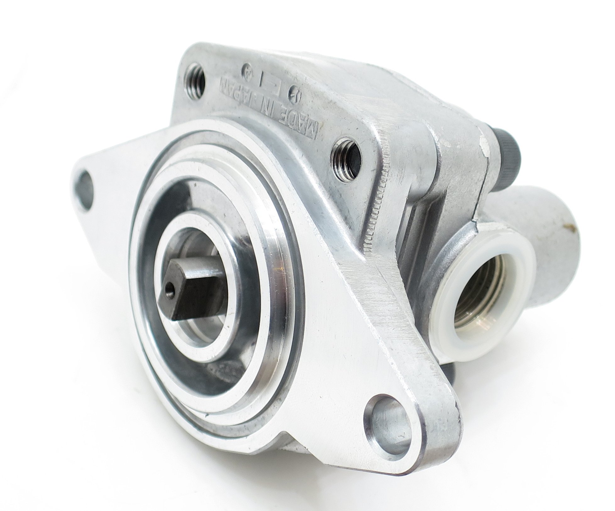
Common pump shafts used in the North America usually fall within four categories; keyed, splined, tapered, or tang. Keyed and spline shafts come in many various sizes and lengths; the most common shafts may be identified using the charts below. Tapered and tang drive shafts are typically application specific, please supply the information from the corresponding figures below.
Pump rotation is always determined with the pump input shaft facing towards the user with the belly of the pump facing down. Gear pumps will have a shaft that is located in the center of the mounting flange that directly connected to a gear. This gear in turn drive the accompanying gear residing in the “belly” portion of the pump.
In a simple gear pump circuit, there are only two lines that connect to the pump. They supply oil from the reservoir, and send the pressure to the system. There are a myriad of hydraulic fitting thread types and sizes. The three most common fitting types that we see used on pumps in the North American market are NPT, SAE O-ring Boss, and SAE O-ring Flange.
NPT stands for National Pipe Taper. Pipe sizes are determined by the inside diameter of the pipe resulting in the thread size to measure nominally larger. For example the outside thread dimension of a ½”NPT fitting actually measures closer to ¾”. The NPT fittings are narrower on one end vs the other. This allows the fitting to “tighten” as the fitting is threaded in. There is a critical difference in pressure ratings between hydraulic rated NPT fittings and those designed for the plumbing and gas industries. Even though they share the same thread dimensions, plumbing fittings should never be used in hydraulics. Pipe thread seals by the galling of the surface are between the metal threads. That is why you should only use a recommended Teflon Paste when using NPT fittings in hydraulics. The paste acts as a lubricant allowing the fitting to make a tighter more efficient seal. The use of pipe tape is strongly discouraged for hydraulic systems.
SAE O-ring Boss straight thread fittings seal with an o-ring at the base of the fitting. The fittings sizes are determined by the inside diameter resulting in the thread size to measure nominally larger. For example, the outside thread dimension of a #6 SAE fitting actually measures 9/16” outside diameter with 18 threads per inch. Most modern hydraulic gear pumps are now using the SAE O-ring boss fittings as they have proven to suffer fewer failure rates for leakage.Some of the most common fitting sizes and types are listed in the chart below:
The male connector SAE O-ring Flange, Code 61 and Code 62 has a flanged head with an O-ring groove machined into the face. The female side is typically a smooth face to accept the O Ring, and four threaded bolt holes in a rectangular shape. The fittings are secured using flange clamp (one or two-pieces) fit over the male flange head and secured to the female side using the four bolts. This compresses the O-ring creating a seal between the male flange and the female port face. There are two common series of this type of fitting referred to as either Code 61 and Code 62. Please see the chart below for identification.
Porting location on gear pumps usually come in either the side or the rear of the pump. There are some replacement pumps that include both side and rear ports. Only one inlet and one outlet should be used. The unused port will need to be blocked off with a hydraulically rated plug.
The volume of oil that Gear pump can flow is determined by the pump displacement and the speed at which it is rotated. Displacement is typically given in cubic inches per revolution or cubic centimeters per revolution.
To determine the unknown displacement of a pump it is necessary to disassemble it to take internal measurements. You will need to measure the outside diameter of one of the gears, the height or thickness of the gear, and the distance from the center to center of the two gears as they are mounted into the pump housing. Below you will find a guide with the formula required to determine the displacement.
Within the hydraulic industry is typically rated in pounds per square inch (psi) or BAR. Ensuring the pump that you are selecting as a replacement is rated for the pressure your system will require is a critical yet often overlooked step. As the displacement goes up within a particular frame size the acceptable working pressure will decrease. It may be necessary to change to a larger frame size to avoid excessive strain on the pump causing premature wear. Remember there is typically a reason that your original pump failed. Gear pumps can be rated from very low pressure for fluid transfer applications to over 4000psi in high pressure industrial environments.
As the displacement goes up within a particular frame size the maximum revolutions per minute (RPM) will decrease. It may be necessary to change to a larger frame size to avoid excessive strain on the pump causing premature wear. Remember there is typically a reason that your original pump failed. Gear pumps typically need a minimum RPM to function efficiency as well. It may be necessary to change the rpm range in which the pump is driven to achieve the required efficiency. If the pump is not directly driven it might be possible by changing a gear, sprocket, or pully diameter. Potential side loading of a pump may change. Anticipated side load may determine whether a bushing or bearing pump may be necessary.


 8613371530291