
tb175 hydraulic pump free sample
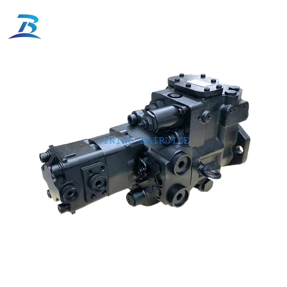
The takeuchi hydraulic pumps are one of the most popular hydraulic pistonches, because they are more adaptable to the pressure-sensitive process, and it has a wide range of pump functions. Tb175 hydraulic pumps are one of the most popular hydraulic pistonches, because they are so adaptable to the pressure of the variation speed, and it has a load-bearing capacity.
The takeuchi hydraulic pumps has a number of positive benefits associated with applying hydraulic pumps. However, the manuals are typically used, which makes it possible to adjust the pressure of the pump"s pressure compared to other types of high-pressure hydraulic pumps. Tb175 hydraulic pumps also work easy as a number of Japan piston hydraulic pump, for example, is a useful choice for pumping with high pressurepressures.
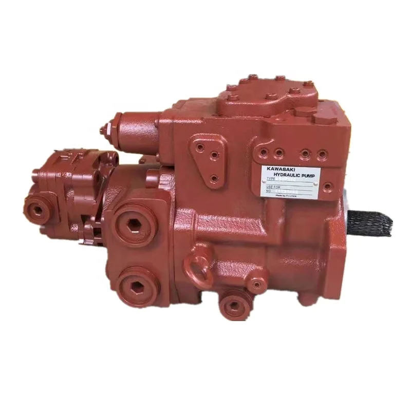
Avoid any downtime at your construction site with the range of takeuchi excavator tb175 hydraulic pump from Alibaba.com. You can check out the fully-stocked parts at Alibaba by manufacturer and model and affordable wholesale prices. The wholesale takeuchi excavator tb175 hydraulic pump collection of spare parts from China’s wholesaler, Alibaba, fits well with a wide range of heavy-duty equipment, from bulldozers, excavators, and hammers, among others. Plus, you can find parts for your tractors, skid steer loaders, wheel loaders, backhoe loaders, and crawler dozers.
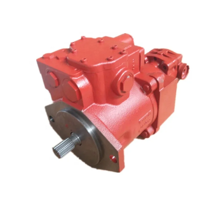
If you have a limited cash allocation, the used or remodeled parts will go a long way in accommodating your budget. Alibaba’s takeuchi excavator tb175 hydraulic pump and tools make it easy to replace, modify and enhance your equipment for their optimal performance. For electrical and mechanical applications, you can find your match at Alibaba.com for everything you need to make your vehicle perform better. Get engine oils, batteries, hydraulic parts, transmissions, injectors, hoses, and starters from the takeuchi excavator tb175 hydraulic pump at Alibaba.com.
The new parts from manufacturers have warranties, and you can buy them by matching the part numbers. Such parts, including hoses, plugs, or filters, will help you quickly deal with downtime on site. The used parts, on the other hand, sell for a lower price. Remember, Alibaba partners with sellers who have certificates of operation. So, you can use these second-hand takeuchi excavator tb175 hydraulic pump to get your heavy machine running. You can also get rebuild models from the collection at Alibaba.com. These are sustainable choices that use recycled materials and perform as well as the new parts. And depending on your seller of choice, you might get a warranty to accompany them.
Brand new final drive directly from South Korean manufacturer by North American representative office. Price includes delivery within Canada and the continental USA Complete and fully assembled brand new hydraulic motor and new heavy-duty planetary gearbox, filled with oil, ready to bolt on and go Quality, built in our own factory in South Korea.
We offer the best performing drives for the major OEM brand machines and high-speed! 2-speed capability, works on either side of your machine and has the same location and size of hydraulic ports as your original for ease of making hose connections. If there is any difference in port location, we supply free hoses together with your final drive to make the conversion easy.

GENERAL CONTENTS Safety Precautions ..............................Cautions during Disassembly and Assembly ......................Cautions during Removal and Installation of the Hydraulic Units ...............10 Cautions during Removal and Installation of Piping ....................11 Handling of Seals ..........................................................
GENERAL Cautions on working on the machine Handling of hoses Fuel, oil or hydraulic fluid leaks can cause a fire. • Do not twist, bend or hit the hoses. • Never use twisted, bent or cracked hoses, tubes and pipes. They may burst. •...
• Do not make hole, weld, or fuse. • Do not subject to shock such as hitting or rolling. • At time of disposal, it will be necessary to release the enclosed gas. Please contact a Takeuchi sales or service agent. Be careful with grease under pressure Pressure can be maintained in the hydraulic circuit long after the engine has been shut down.
GENERAL CAUTIONS DURING DISASSEMBLY AND CAUTIONS DURING REMOVAL AND INSTALLA- ASSEMBLY TION OF THE HYDRAULIC UNITS 1. Clean the machine before disassembly opera- 1. Make sure that the temperature of the hydraulic tion. oil has dropped. 2. Before disassembly, check the machine condi- 2.
GENERAL CAUTIONS DURING REMOVAL AND INSTAL- HANDLING OF SEALS LATION OF PIPING 1. Clean the grooves for O-rings and if there is any 1. When hydraulic hoses are installed, tighten them burr, etc., remove it. once to the prescribed torque, then loosen them slightly and retighten them to the prescribed torque.
GENERAL TIGHTENING TORQUES Hydraulic Hoses Torque Hose Fitting Size Union Nut (G) Taper Thread (R) N·m ft-lb N·m ft-lb +4.9 +3.5 11.8 ±1.2 8.7 ±0.8 +4.9 +3.5 24.5 18.1 29.4 ±2.9 21.7 ±2.1 +4.9 36.2 +3.5 53.9 ±5.4 39.8 ±3.9 58.8 +4.9 43.4...
SPECIFICATIONS NAMES OF COMPONENTS NAMES OF COMPONENTS 1. Cab 10. Axle Lock Cylinder 19. Dozer Blade Cylinder 20. Swivel Joint 2. Engine Hood 11. Engine 3. Fuel Tank 21. Bucket 12. Tire 4. Hydraulic Tank 13. Axle 22. Bucket Cylinder 23.
SPECIFICATIONS SPECIFICATIONS TABLES Tire Front Tire: Qty. Size 8.25-20-12PR Tire Pressure Steering System Type Front Setting System Operation Type Hydraulically-Operated Breake Device Travel Brake Type Front and rear wheel braking, direct acting hydraulic disk with brake lock Parking Brake Type Rear wheel braking disk Outrigger (Option) Type...
SPECIFICATIONS STANDARDS FOR JUDGING PERFORMANCE METHODS FOR INSPECTING PERFOR- MANCE Hydraulic Oil Pressure (Main Relief Valve Set Pressure) Travel, Boom, Arm Measuring Method • Engine : Maximum r.p.m. • Hydraulic Oil Temp. : 50~60°C • Mount the pressure gauge on the pressure detec- tion port, operate the desired hydraulic circuit and measure the relief pressure.
SPECIFICATIONS STANDARDS FOR JUDGING PERFORMANCE Dozer Blade Measuring Method • Engine : Maximum r.p.m. • Hydraulic Oil Temp. : 50~60°C • Mount the pressure gauge on the pressure detec- tion port, operate the desired hydraulic circuit and measure the relief pressure. Pressure Detection Port Relief Circuit...
SPECIFICATIONS STANDARDS FOR JUDGING PERFORMANCE Hydraulic Oil Pressure (Slewing Relief Valve Set Pressure) Measuring Method • Engine : Maximum r.p.m. • Hydraulic Oil Temp. : 50~60°C • Mount the pressure gauge on the pressure de- tection port and set a solid obstacle so that the upperstructure cannot slew in the direction to be measured.
SPECIFICATIONS STANDARDS FOR JUDGING PERFORMANCE Hydraulic Oil Pressure (Pilot Relief Valve Set Pressure) Measuring Method • Engine : Maximum r.p.m. • Hydraulic Oil Temp. : 50~60˚C • Mount pressure gauge on the pressure detection port and measure the pilot relief pressure. Pressure Detection Port Relief Valve Port Position...
SPECIFICATIONS STANDARDS FOR JUDGING PERFORMANCE Slew Time • Engine : Maximum r.p.m. • Hydraulic Oil Temp. : 50~60°C • Measurement Posture : Completely retract the arm cylinder, fully extend the bucket cylinder and adjust so that boom foot pin and bucket pin are at matching height.
SPECIFICATIONS STANDARDS FOR JUDGING PERFORMANCE Arm Cylinder Speed • Engine : Maximum r.p.m. • Hydraulic Oil Temp. : 50~60°C • Measurement Posture : Completely retract the arm cylinder, fully extend the bucket cylinder, position the arm horizontally and rest the dozer blade on the ground.
SPECIFICATIONS STANDARDS FOR JUDGING PERFORMANCE Adjust Cylinder Speed • Engine : Maximum r.p.m. • Hydraulic Oil Temp. : 50~60°C • Measurement Posture : Completely retract the arm cylinder, fully extend the bucket and boom cylinders, position the arm horizontally and rest the dozer blade on the ground.
MACHINE CONFIGURATION CONTENTS Drive System ................................3 Slew System ................................9 Travel System ............................... 11 Upper Frame .................................13 Control System..............................21 Attachments ................................27 Hydraulic System ..............................33 Electrical System ..............................37 Air Conditioner System ............................44 TB175W III-...
3. Engine Foot RL Apply thread-locking compound. 12. Pipe 4. Engine Foot RR E: “A” Mark 13. Bracket 5. Stopper N·m 14. Silencer 6. Stopper .9 N·m 15. Gasket 7. Cushion Rubber 16. Gasket 8. Cushion Rubber III- III- TB175W...
13. Hose 3. Hose 14. Hose 4. Hose 15. Sub Tank 5. Pipe 16. Bracket 17. Plate 6. Pipe 7. Pipe 18. Hose 8. Pipe 19. Sensor 9. Hose 20. Joint 10. Hose 21. Hose 11. Drain Vave TB175W III-4 III-4...
Radiator and Oil Cooler 8. Bracket 1. Stay 9. Bracket 2. Stay 10. Guard 3. Shroud 11. Cushion Rubber 4. Plate 12. Radiator and Oil Cooler 5. Plate 13. Cushion Rubber 6. Plate 14. Guard 7. Net III-5 III-5 TB175W...
P3 P4 • Refer to the table concerning the responsibility of each of the pumps shown in the drawing at right. Travel, Bucket, Boom[1], Arm[2] Travel, Auxiliary, Boom[2], Arm[1], Swing Outrigger, Slew, Auxiliary Steering, Brake W2C104 Pilot Pressure TB175W III- III-...
C:Upon assembling, inspect the continuity using a 9. Plug 2. Resistor testerwhenthelevelswitchfloat(13)isatONand 10. Level Switch OFF positions. 3. Switch FloatisatOFF(upper)positionThereisnocontinuity. 11. Strainer 4. Relay FloatisatON(upper)positionThereisnocontinuity. 12. Pump 5. Wire Harness 13. Float 6. Diode (3A, yellow) 7. Hose TB175W III-8 III-8...
MACHINE CONFIGURATION UPPER FRAME Floor Plate W2C401 1. Floor Plate 2. Floor Mat 3. Cover 4. Stage 5. Tube 6. Tube 7. Rubber 8. Cover 9. Cover 10. Pipe TB175W III-14...
D: Grease with molybdenum disulfide applied. 23.5 N·m 1. Cover 9. Filter 2. Plate 10. Cover 3. Selector Damper 11. Hose 4. Bracket 12. Hose 5. Panel 13. Heater Assembly 6. Cover 14. Switch 7. Wire 15. Valve 8. Wire III-15 TB175W...
10. Pilot Lamp 3. Louver 11. Pilot Lamp 4. Defroster Hose 12. Pilot Lamp 5. Parking Brake Switch 13. Pilot Lamp 6. Site Travel Switch 14. Creeping Travel Switch 7. Axle Lock Switch 15. Ornament 8. Light Switch TB175W III-16...
C: Actuator Relay 3. Plate 11. Terminal D: Main Relay 4. Relay 12. Clamp E: Starter Relay 5. Relay 13. Cover 14. Battery Switch 6. Sheet 12.3 N·m 7. Battery 15. ECU .8 N·m 8. Bracket 16. Ground Cable III-17 TB175W...
4. Side Cover R 12. Plate 20. Hinge 5. Front Cover 13. Stay 21. Gas Spring 6. Center Cover F 14. Stay 22. Under Cover 15. Hook 7. Center Cover T 23. Plate 8. Under Cover 16. Wire 24. Under Cover III-1 TB175W...
20. Substructure, Compl. 28. Pedal 5. Spring 13. Washer 21. Plate 29. Steering Wheel 6. Shield 14. Half Bowl 22. Stop 30. Turning Handle 31. Cap 7. Covering 15. Substructure 23. Spring 8. Spring 16. Segment 24. Shaft 32. Switch III-21 TB175W...
T6 ↔ SST SSP ↔ PM5 22. Selector Valve (2-Piece Boom) AS2 ↔ 5Pa5 Dr ↔ T5 23. Pipe AST ↔ TM1 PDB ↔ 5Pa3 24. Solenoid Valve ASP ↔ A5 PA ↔ 4Pa2a BS2 ↔ 5Pb1 PPL ↔ 4Pa4 III-23 TB175W...
2. Cover 6. Cluster Gauge 11. Safety Lock Button 3. Cover 7. Starter Switch 4. Panel Cover R 8. Slew Speed Switch 12. Fuse Box Control Box l Air Conditioner W2C507E 1. Panel Cover L 2. Cover 3. Clamp TB175W III-24...
1. Dozer Blade Lever 4. Control Cable 7. Hinge 2. Bracket 5. Yoke 3. Cover 6. Cigarette Lighter Swing Pedal VIEW B W2C509E 1. Bracket 3. Cover 5. Elbow 2. Swing Pedal 4. Bushing 6. Pilot Valve (Swing) III-25 TB175W...
MACHINE CONFIGURATION CONTROl SYSTEM Pilot Valve (Brake) W2C510 1. Pilot Valve (Brake) 3. Elbow 2. Adapter 4. Adapter Pilot Valve (Travel) 2, 4 2, 3 VIEW A W2C511E 1. Pilot Valve (Travel) 3. Elbow 2. Bushing 4. Elbow TB175W III-26...
17. Grease Nipple 29. Pin 7. Clamp 18. Boom Light 30. Plate 8. Cover 19. Bulb 31. Grease Nipple 9. Wire Harness 20. Boom Cylinder 32. Elbow 21. Arm Cylinder 10. Rubber 33. Elbow 11. Bracket 22. Boom adjustment Cylinder III-27 TB175W...
11. Pipe of 0.5~1.0 mm when tightening the double nuts. 3. Clamp 12. Cap 4. Hose 13. Grease Nipple 5. Pipe 14. Hose 6. Hose 15. Hose 7. Clamp 16. Hose 8. Adapter 17. Cap 9. Pipe R TB175W III-28...
6. Protector 26. Arm Cylinder 36. Band 17. Pin 7. Pipe R 27. Hose 37. Band 18. Pin 8. Pipe L 28. Hose 38. Band 19. Pin 9. Pipe 29. O-ring 20. Shim 30. Tube 10. Wire Harness III-29 TB175W...
6. Bucket Link 28. Plate 17. Grease Nipple 7. Bushing 29. Cap 18. Elbow 8. Bushing 30. O-ring 19. Elbow 31. Elbow 9. Dust Seal 20. O-ring 10. Guide Link L 21. Bucket Cylinder 11. Guide Link R 22. Hose TB175W III-30...
(6)andflange. 8. Insert the shims which were just removed be- tween the flange and the end plate, then reas- semble the parts. Tighten the 3 bolts uniformly. Bolt: 83 N·m 9. Return the O-ring to its proper position. III-31 TB175W...
2. Air Breather 11. Sight Gauge 3. Cover 12. Plug 4. Cover 13. O-ring 5. Spring 14. Check Valve 6. Filter Element 15. Snap Ring 7. Check Valve 16. Adapter 8. Suction Filter 17. Washer 9. O-ring 18. Bushing III-35 TB175W...
Parking light relay 4. Wire Harness f: Head light relay 13. Buzzer 5. Diode (3A yellow) g: Change speed relay 14. Fuse Box 6. Plate h: Hazard relay 15. Bracket 7. Resistor 16. Hour Meter 8. Detector III-41 TB175W...
MACHINE CONFIGURATION ELECTRICAL SYSTEM 17540001~17540134 17540001~17540134 17540001~17540094 17540135~ W3C802 1. Wire Harness 2. Fusible Link 3. Short Connector 4. Diode (3A yellow) 5. Short Connector 6. Wire Harness 7. Wire Harness 8. Diode (3A yellow) 9. Guard 10. Horn TB175W III-42...
8 mm when 3. Shaft 10. Valve pressed with a force of about 98N. 4. Collar 11. Adaptor 5. Compressor 12. Bushing 6. Pulley 13. Elbow 7. Hose 14. V-Belt III-45 TB175W...
MACHINE CONFIGURATION AIR CONdITIONER SYSTEM Air Conditioner 1/2 1. Bracket 2. Cover 3. Condenser 4. Fun 5. Dryer 6. Bracket 7. Hose 8. Hose 9. Switch 10. Connector TB175W III-46...
1. Hose 2. Guard 3. Wire Harness 4. Air Conditioner Unit 5. Wire 6. Wire Harness 7. Relay 8. Valve 9. Tube 10. Cover 11. Panel 12. Hose 13. Hose 14. Hose 15. Louver 16. Adaptor 17. Louver III-47 TB175W...
2. Evaporato 3. Heater Core 4. Filter 5. Blowier Motor 6. O-Ring 7. O-Ring 8. Expansion Valve 9. Thermo Stat 10. Air Condiitioner Switch 11. Knob 12. Cable Control Converter 13. Cable Control Converter 14. 3-Speed Rotary Switch TB175W III-48...
A bigger heater core, air conditioning evaporator coil, condenser, blower or fan may be included. Often, on long haul trucks, auxiliary air condi- tioning and heater components and controls are added. The objective remains the same, to move heat energy and maintain occupant comfort. TB175W III-48...
Please study it for a moment. Note the information printed next to each component. Remember that the com- ponents may be positioned and attached to the truck in various locations. III-49 TB175W...
One way valves inside the compressor separate the compressed gas (high pres- sure) side of the system from the suction (low pressure) side. Figure 2-3 shows a cutaway view of a compressor with the high and low pressure sides noted. TB175W III-50...
The refrigerant gas gives up a lot of heat energy to the outside air as it “changes state” in the condenser. Figure 2-5 illustrates a condenser. Air moving through the condenserabsorbsheatfromtherefrigerant.Theamountofairflowthroughthecon- denser is the major factor in how well the condenser functions. III-51 TB175W...
Figure 2-6 This cutaway view of a receiver-driershowsthefil- ter elements, inlet, outlet and refrigerant path. The sight glass is a small window into the system used in diagnosis and when adding refrigerant (charging the system). TB175W III-52...
The refrig- erantabsorbsheatfromtheairwhentheblowerforcestheairthroughthefins.When the thermostat probe senses the upper limit of the thermostat heat setting, a circuit closes. The compressor clutch engages and the compressor operates and moves more refrigerant to the high side of the system. III-53 TB175W...
In operation the AC system is under load and high side pressures normally range between 150 and 250 pounds per square inch for R-12 and higher for some other refrigerants. TB175W III-54...
Additional heater controls, ducts, air vents, blend-air doors, temperature regu- lating devices and auxiliary heaters may be installed as part of a heater system. These may be air, vacuum, electrical or mechanically operated. III-55 TB175W...
90’s or low 100’s. The AC unit must remove a lot of moisture from the air in the cab as the air movesthroughtheevaporatorfins.Themoremoistureonthefins, the less effective the transfer of heat is to the refrigerant inside the evaporator coil. TB175W III-56...
• Environmental conditions affect how both heaters and air conditioners work. Weather, driving conditions, color of the vehicle are factors. All contribute to heat gain or loss inside a cab and how much heat energy must be moved to maintain occupant comfort. III-57 TB175W...
The following inspection procedures should take about 15 to 20 minutes, longer if corrective steps, part replacement or adding refrigerant is necessary. There is a “Preventive Maintenance Worksheet” you may use at the end of this chapter, Figure 7-9 TB175W III-58...
2. Inspect Parts Look at the system for what might come loose, leak, wear out or become dirty and not function the way it should. The main points for visual inspec- tion of the system are emphasized in Figure 7-2. III-59 TB175W...
Tighten all mounting bolts as you in- spect the system. Slots in the mounting bracket are used to move the compressor clutch assembly in order to adjust belt tension or alignment. TB175W III-60...
AC system. AC service procedures for complete system recovering of refrigerant, evacuating, and recharging are covered and illustrated in Chapter 9. Note: A leaking heater core could also result in coolant at the condensate drain. III-61 TB175W...
Look for any corrosion on leads or connectors and clean them. Make sure all leads and wires are properly supported and securely connected. 2. Check Electrical Current Flow and Device Functions Performthefollowingstepstocheckcurrentflowandelectricaldevicefunc- tions: A.TurntheIgnitionOn–Tocheckcurrentflowtheignitionmustbe TB175W III-62...
The roof mounted condenser fans may come on when the system is turned on. Like the thermostat and most clutches, the normal on-off cycling action can not be observed until the engine is running with the AC system on. III-63 TB175W...
The needle movement is called “temperature swing.” When you can adjust the thermostat setting, the range of swing should change. For ex- ample, from full cooling (cold) to moderate (between cold and warm), the swing may change from 32-38 to 32-42 degrees. TB175W III-64...
Figure 7-7 illustrates and explains what you may observe in the sight glass. Roof mounted condenser fans may run continuously or cycle on and off. If you can’t tell by sound you may have to climb a ladder and ob- serve the fan blades. III-65 TB175W...
As the engine warms up, feel the heater return hose. If the hose feels warm or hot, the heater control valve is leaking internally. This type of leak can seriously reduce air conditioning per- formance. TB175W III-66...
Heater/cooling electrical and valve component inspection is the same as air conditioner inspection. The controls are operated to see if they function correctlytomaintainorvarycabtemperatureandairflow. Preventive Maintenance Worksheet Please feel free to modify or copy the worksheet in Figure 7-9. Actual vehicle use,mileage,operatingconditionsandmaintenancebudgetmayinfluenceservice frequency. III-67 TB175W...
When you check the electrical circuit, begin with the engine off but ignition on. A system performance inspection with the engine run- ning and system on really combines electrical and AC or heater system function. TB175W III-68...
2. The vehicle operator"s knowledge and experience—question him or her. 3. The work order. 4. Good test equipment and the HVAC system The routine you follow when troubleshooting should proceed from the most to least productive way of locating the problem and fixing the cause. TB175W III-70...
8-1 we have used numbers on the illustration to track normal air conditioner func- tion. Figure 8-1 An illustration of the typical HVAC system. The numbers follow the action when the AC part of the system is working properly (moving heat out of the cab and into the outside air). III-71 TB175W...
He was in such a hurry he didn’t tell you anything except that the air conditioner wasn’t cooling. Here is the best way to handle that kind of situation. TB175W III-72...
AC service. • Doyougetanycoolingatall? Answer: Yes but it seems to quit after a while. • Doyoustillgetairflowattheventsfromtheblower? Answer: Yes. • Whenwasyourairconditionercheckedthoroughly? Answer: Before I bought the rig last May (a year ago). • HastheheaterbeenusedrecentlyanddiditworkOK? Answer: Yes. III-73 TB175W...
The manifold gauge set is a necessary tool in troubleshooting AC system prob- lems. The following steps are performed during and after installing the manifold gauge set: 1. PurgingAirfromtheGaugeSetHoses 2. AddingRefrigeranttotheSystem 3. StabilizingtheACSystem. III-75 TB175W...
AC system is maintained on a regular basis. When adding refrigerant to the system, connect the center hose from the manifold gauge set to the refrigerant dispensing valve on the container. Fig- ure 8-4 illustrates this connection. TB175W III-76...
2. Open the refrigerant dispensing valve on the container and then the low pressure hand valve on the manifold. This allows refrig- erant to enter the system as a gas on the low pressure or suction side of the compressor. The compressor will pull refrigerant into the system. III-77 TB175W...
3. Stabilizing The AC System For reliable gauge readings as an aid in troubleshooting, the AC system must be stabilized. Be sure your tools and test equipment are clear of all mov- CAUTION ing parts of the engine and air conditioner. TB175W III-78...
Low Refrigerant Charge in the System Figure 8-5 Gauge reading, low refriger- ant charge in the system. Tip: You see bubbles in the sight glass. The air from vents in the cab is only slightly cool. Cause: Insufficient refrigerant (charge) in the system. III-79 TB175W...
Note: It may be necessary to use a jumper wire to bypass some types of low pressure cutout switches to operate the compressor (clutch) when you add refrigerant to the system. TB175W III-80...
(there is no way to tell). Check the compressor and replace any refrigeration oil lost due to leakage. Evacuate and recharge the system with refrigerant, then check AC operation and performance. III-81 TB175W...
AC operation and performance. Figure 8-9 Expansion Valve (TXV) Stuck Closed or Plugged Gauge reading, expansion valve (TXV) stuck closed. Tip: Air from vents in the cab is only slightly cool. The ex- pansion valve body is frosted or sweating. TB175W III-82...
Remove, clean and replace the screen, then reconnect the hose. Any signs of contamination will require flushing the system. Next, replace the re- ceiverdrier. Then evacuate and recharge the system with refrigerant, and check AC operation and performance. III-83 TB175W...
2. The low pressure (suction) side gauge needle should now drop on the gauge. This indicates the valve has closed and is not stuck open. Repeat the test, but first warm the valve diaphragm with your hand. TB175W III-84...
The hose or line may be cool to the touch near the restriction. Cause: There could be a kink in a line, or other restriction in the high side of the system. III-85 TB175W...
R-12 from systems containing Schrader valves. Remove the compressor cylinder head and check the appearance of the reed valve plate assembly. If defective, replace the valve plate and install with new gaskets, or replace the com- pressor assembly. TB175W III-86...
The high pressure hoses and lines will be very hot. Don’ t forget to check the engine cooling system compo- nents—fan and drive belt, fan clutch operation, and the radiator shutter. III-87 TB175W...
(it may be par- tially plugged) or replace the condenser. Also replace the receiver-drier or accumulator. Then connect the components and evacuate the system. Recharge the air conditioner with refrigerant and check system operation and performance. TB175W III-88...
Don’t kink or break the tube. Position the new thermostat capillary tube at or close to the same location and seating depth between the evapo- rator coil fins as the old one. Connect the electrical leads. III-89 TB175W...
When refrigerant and refrigera- tion oil leaks out of a system or there is contamination blocking oil flow, the compressor will be starved for oil and seize. TB175W III-90...
When the system is charged with refrigerant, the pressure goes from minus (a vacuum) to plus pressure inside the hoses and all components. The refrigerant and refrigera- tion oil are trying to escape from the system at all times. III-91 TB175W...
But there was no way to tell without using your knowledge and experience. By now you are pretty familiar with AC system problems, the reasons for some of them, troubleshooting and repair. In Chapter9 we will describe com- plete system purging, evacuation, flushing and recharging. TB175W III-92...
Cylinders ................................99 Dozer Blade Cylinder ............................115 Ram Lock Cylinder ............................117 Slew Motor ................................ 123 Axle Type: 279/172 Axle Type: 212 (Front) Axle Type: 112 (Rear) Travel Motor Type: A6VM Drop Box Type: 357 Swivel Joint Type: 532 IV-2 TB175W...
66. Spring Pin 11. Spring 25. Ball 39. Pin 53. O-ring 67. Adjusting Screw 12. Swash Plate 26. Pin 40. Piston 54. O-ring 13. Bushing 27. Lever 41. Pin 55. O-ring 14. Pin 28. Piston 42. Case 56. O-ring IV-3 TB175W...
P1 and P2 and discharge pressure from pump P3 act on the piston (9). Also, the discharge pressure selected by the shuttle valve (11) and transmitted through the sleeve (2) and spool (6) acts on the servo piston (10). L3D103 IV-4 TB175W...
P1 and P2 but also by the pump P3. Thus, the P-Q curve for the piston pumps shows that the engine"s power is fully utilized (full horse power control). L3D124E IV-5 TB175W...
1. Loosen the drain plug (1) and drain out the oil. L3D106 2. Remove the cap screws and remove the gear pump. 3. Remove the coupling. L3D107 4. Remove the cap screws and remove the cover. • Remove the cover in horizontal condition. L3D108 IV-6 TB175W...
(5), and the pistons (6) from the cylinder block (7). • Disassemble the inside of the cylinder block (7) only when required. L3D111 7. Remove the swash plate. 8. Remove the pin R and pin L. L3D112 IV-7 TB175W...
10. Remove the cap screws and remove the cover. 11. Remove the two springs [inside, outside]. 12. Remove the spring seat. L3D114 13. Remove the cap screws and remove the cover. 14. Remove the lever. L3D115 15. Remove the sleeve, the spool and piston. L3D116 IV-8 TB175W...
L3D118 18. Loosen the lock nut (3) and remove the adjusting screw (2). • Record the length of the adjusting screw pro- trusion before starting the disassembly. L3D119 IV-9 TB175W...
3. Install the drain plug (1). L3D106 4. Install the oil seal. 5. Install the shaft in the housing. • Tap the spline end with a plastic hammer to positively install the outer race of the bearing in the housing hole. L3D120 IV-10 TB175W...
• Insert the bushing into the swash plate. • Apply grease on the sliding surfaces of the swash plate, pin R and pin L. L3D122 8. Mount the pin and tighten the plug. Plug: 29.4 N·m L3D117 9. Mount the piston in the housing. L3D123 IV-11 TB175W...
Install the guide (3) in the cylinder block. • Apply grease to the spherical part of the guide. c. Attach the pistons (6) to the shoe holder (5), and install the shoe holder (5) in the cylinder block. L3D111 IV-12 TB175W...
Cap screw: 235 N·m L3D108 20. Install the coupling on the end of the main pump shaft. 21. Unite the main pump and gear pump and fix them with the cap screws. Cap screw: 56.9 N·m L3D107 IV-13 TB175W...
• No abnormal scratches, wear, or • Exchange driven gear flaking of the tooth surfaces Ball bearings and • No abnormal scratches, wear, or • Exchange the shaft needle bearings flaking of the rolling surfaces and the assembly. IV-14 TB175W...
• Replace the seals. • The shaft surface which slides against • Replace the shaft or replace the pump. the oil seal is worn. • The plug or bolts are loose. • Tighten them or replace the seals. IV-15 TB175W...
By turning the drive shaft (3), the space between the case and the gears is filled with oil. This oil is thus sent through the pump from the inlet to the outlet. INLET OUTLET Y1-D101E IV-17 TB175W...
3. Remove the snap ring (3) and the oil seal (4) from the flange (1). • Be careful not to scratch or otherwise damage the flange. • When re-assembling, install the oil seal using the jigs A and B. L4D151 T7D152 IV-18 TB175W...
• Be careful not to scratch or otherwise damage the inside of the housing. L4D154 7. Remove the gasket (2) from the adapter plate (11). DISCHARGE SIDE 8. Remove the backup ring (5) and gasket (6) from the adapter plate (11). SUCTION SIDE L4D155E IV-19 TB175W...
• Be careful not to scratch or otherwise damage the inside of the rear cover. 12. Remove the gasket (18), (19) from the bushing (13) and the bushing (14). L4D156 • Be careful to keep the bushings separated and in their original places. IV-20 TB175W...
• There are marks from foreign matter biting into the sliding surface of the bearing inner diameter and the side surface. Dirty hydraulic oil is one likely cause of such wear. In such a case, replace the hydraulic oil and flush out affected hydraulic circuit completely. IV-21 TB175W...
3. Run the pump for 10 minutes under the conditions the test. in (2), then increase the engine’s speed to 1,500~2,000 rpm and run it for another 10 min- utes. IV-22 TB175W...
2. Open the tester’s loading valve and start the engine. 3. Run the engine at the rated speed. 4. Gradually close the loading valve and apply the rated pressure to the pump (2). 5. Measure the discharge volume and the pump’s speed (engine speed). IV-23 TB175W...
• Clean the suction filter and suction side piping. • Aeration is occurring. • Check for insufficient tightening of pipes, etc. and repair. • Viscosity of the hydraulic oil is too • Replace the hydraulic oil with oil of the low. proper viscosity. IV-24 TB175W...
CONTROL VALVE (MONO-BLOCK) CONSTRUCTION VIEW Z W2D200E 1. Right Travel Section 2. Bucket Section 3. Boom [1] Section 4. Arm [2] Section 5. Left Travel Section 6. Auxiliary Section 7. Boom [2] Section 8. Arm [1] Section 9. Swing Section IV-25 TB175W...
SECTION ÒB-BÓ SECTION ÒA-AÓ L3D201E 1. Cover 7. Cover 13. Poppet 2. Spool End 8. O-ring 14. O-ring 3. Holder 9. Shuttle 15. Plug 4. Spring 10. Spring 16. Spring 5. Spring 11. O-ring 6. O-ring 12. Plug IV-26 TB175W...
CONTROL VALVE 8 910 2 3 4 3 5 SECTION ÒD-DÓ SECTION ÒC-CÓ L3D202E 1. Housing 6. Port Relief Valve 2. O-ring 7. O-ring 3. Spring Holder 8. Plug 4. Spring 9. Spring 5. Spool End 10. Poppet IV-27 TB175W...
3. Spring 11. Backup Ring 19. Poppet 4. Poppet 12. O-ring 20. Anti-Drift Valve 5. Spring 13. Spring 21. Spacer 6. Poppet 14. Poppet 22. Spring 7. Sleeve 15. Sleeve 23. Poppet 8. Port Relief Valve 16. Plug IV-28 TB175W...
L3D204E 1. Port Relief Valve 9. O-ring 2. Plug 10. Backup Ring 3. O-ring 11. Plug 4. Spring 12. O-ring 5. Poppet 13. Plug 6. Port Relief Valve 14. Sleeve 7. Poppet 15. Spring 8. Spring 16. Poppet IV-29 TB175W...
Anti-Drift Valve 1. Body 2. Poppet 3. Plug 4. Piston 5. Spool 6. Sleeve 7. Spring 8. Spring 9. O-ring 10. O-ring 11. Backup Ring 12. Backup Ring 13. O-ring 14. Plug 15. O-ring 16. Spring Holder L2D208 IV-31 TB175W...
5-section part passes through the passage (10), signal lands of indi- vidual spools of the 4-section part, signal land (11) of the bucket spool, and then flows into the tank passage IV-32 TB175W...
(4). Then the oil flows through left travel operations. the passage (5) and the head of the spool (1), and enters the port 4A2. The return oil flows from the port 4B2 through the head of the spool (1), and back to the IV-33 TB175W...
(11) to close the center bypass valve (13). The oil supplied from the pump P2 passes through the parallel passages (14), load check valve (15), passage (16), the head of the spool (12), and the IV-34 TB175W...
(3), load check valve (4), passage (5), and the head of the spool (1), and then flows into the port 5B1. The return oil flows from the port 5A1 through the head of the spool (1), and back to the tank passage (6). IV-35 TB175W...
Switching the spool (1) of the arm [1] causes the spool head of the spool (1) of the arm [1], and back to the (17) of the arm [2] to be switched by the passage (8) tank passage (15). 2. Load L2D217 IV-36 TB175W...
Part of the oil from the pump P2 flows through the parallel passages (4), orifice (10), and load check valve (11), and is supplied to the travel section to relieve the deceleration shock at the time of switching of the straight travel spool (3). IV-37 TB175W...
(5) to flow through the passage (4) into the tank port Dr1. This opens the poppet (1), and the return oil from the cylinder port 4B3 flows through the spool of the boom [1] and back to the tank. L2D221 IV-38 TB175W...
When the pressure is applied to the pilot port PH, the piston (8) is pushed to the left to hit the plug (9). Then, the spring force of the spring (7) becomes larger, increasing the pressure in chamber B. W2D210 IV-39 TB175W...
C on the inside drops. Compared to the chamber B side, the pressure in chamber C is low and there is no equilibrium in pressure. For this reason, the main poppet (6) opens and pressurized oil flows to the tank passage (T). TB175W IV-40...
When the pressure in chamber B is lower than the pressure in the tank passage (T), the differences in the sectional areas A and A1 cause the main poppet (6) to open. Thus, sufficient oil from the tank passage (T) enters chamber B, filling the empty space. IV-41 TB175W...
• Install the valve in the same position as it was in before disassembly. Valve: 59~69 N·m W2D211 3. Remove the plug (4), then remove spring (5) and spool (6). Next, remove the O-ring from the plug. Plug: 78~88 N·m W2D212 IV-42 TB175W...
7. Disassemble the right travel plug (20). Next, remove the O-ring from the plug. Plug: 105.9~141.2 N·m L3D228 8. Remove the cap screws, then remove cover (21). Next, remove the O-ring from the cover. Cap screw: 8.8~10.8 N·m L3D229 IV-43 TB175W...
(35). Then remove the O-ring and backup ring from the plug (33). • Screw the bolt into the screw hole (M6 × 1.0) at the end face of the plug, and grab the bolt to pull out the plug. L3D236 IV-44 TB175W...
9. Remove the O-ring (16) and backup ring (17) from the spacer (15). 10. Remove the spring (18) and poppet (19) from the body (14). L2D240 IV-45 TB175W...
5. Remove the O-ring (13) from the plug (11). 6. Loosen the lock nut (14) and remove the plug (15). 7. Remove the O-ring (16) from the plug (15). W2D214 8. Remove the spring (17) and needle valve (18). IV-46 TB175W...
• Damage to poppet contact surface. • Replace • Abnormality in the spring. • Replace • O-rings, backup rings, seals • As a rule, all these should be replaced. Adjusting the Main Relief Valve Pressure “II. Specifications, Standards for Judging Per- formance” IV-47 TB175W...
• Foreign matter is biting into the load • Disassemble and check, then overhaul shifting to a lift operation. check valve seat or large scratches were or replace. made by foreign matter biting into the valve"s seat previously. IV-48 TB175W...
• Spool stroke is not the specified stroke. • Check if there is something interfering with the link mechanism. Check if a pin or a pin hole in the link connection is worn or not. IV-49 TB175W...
3. Slew Flow Control Section Assembly 4. Dozer Blade Section Assembly 5. Slew Section Assembly 6. Outlet Housing 7. Main Relief Valve 8. Port Relief Valve 9. Spacer Section 10. Slow Slew Speed Adjusting Valve 11. Auxiliary Section Assembly 12. Port Relief Valve IV-51 TB175W...
10 7 6. Load Check Valve 7. Spring 8. Wiper 9. O-ring 10. O-ring L3D251 Slew Section 1. Cover 2. Screw 3. Spring Holder 4. Spring 5. Cover 6. Load Check Valve 7. Spring 8. O-ring 9. O-ring L3D252 IV-52 TB175W...
4. Spring 5. Cover 6. Load Check Valve 7. Spring 8. O-ring 9. O-ring W2D217 Outlet Housing 1. Filter 2. Orifice L3D253 Spacer Section 1. Plug 2. Adjusting Screw 3. Nut 4. O-ring 5. O-ring 6. O-ring L3D254 IV-53 TB175W...
16. O-ring 7. Spring 17. O-ring 8. Spring 18. Wave Washer 9. Adjusting Screw 19. O-ring 10. Washer Port Relief Valve 1. Housing 2. Adjusting Screw 3. Poppet 4. Spring 5. Lock Nut 6. O-ring 7. O-ring C4D205 IV-54 TB175W...
A load check valve (5) is included in each section except the travel (right, left) sections. This valve prevents oil from flowing backward due to the load pressure (C) from the actuator port during switching of the spool. IV-55 TB175W...
In this way, only a specific quantity of the oil supplied flows to the slew motor even when the supply pres- sure changes, the remaining being release to tank port T2. This makes it possible to slew in the slow speed mode with a slow flow. IV-56 TB175W...
(2), and this hydraulic pressure pushes the main poppet toward the right. As a result, the pressurized oil in the circuit flows to the tank passage. This operation maintains the pressure in the circuit at the set value. S3F612 IV-57 TB175W...
C on the inside drops. Compared to the chamber B side, the pressure in chamber C is low and there is no equilibrium in pressure. For this reason, the main poppet (6) opens and pressurized oil flows to the tank passage (T). IV-58 TB175W...
A from the actuator port. If this pressure becomes stronger than the set value of the spring (1), it pushes the poppet (2) to the right side and pressurized fluid from the actuator port flows to the tank passage. IV-59 TB175W...
• Do not disassemble the relief valves unless it is necessary. • When using a spanner or adjustable wrench, be sure to attach it in the place shown in the figure at right. Relief valve: 68~78.5 N·m G4D223 IV-60 TB175W...
1. Remove the cap screws (5), the cover (6) and the spool assembly (7). Cap screw: 7.3 N·m 2. Loosen the screw (8) from the spool assembly (7). Screw: 5.2 N·m 3. Remove the spring holder (9), spring (10), and spring holder (9). IV-61 TB175W...
Screw: 2.5 N·m Pilot Operated Section 1. Take out the cap screw (5) and remove the cover (15), then remove the O-ring (16) from the cover (15). Cap screw: 7.3 N·m 2. Remove the spool from the section. K3D217 IV-62 TB175W...
3. From the opposite side of the block, remove cap screws (7), then remove cover (8), piston (9), pin (10) and sleeve (11). Cap screw: 9.8 N·m 4. Remove O-ring (12) from cover (8). 5. Remove O-ring (13) from sleeve (11). IV-63 TB175W...
O-ring (13) from the adjusting screw (12). • During assembly, after installing the adjusting screw (12), lock the lock nut (10) temporarily, then tighten it after adjusting the pressure. Lock nut: 27~31 N·m 6. Remove the spring (14) and needle valve (15). W2D220 IV-64 TB175W...
• Damage to poppet contact surface. • Replace • Abnormality in the spring. • Replace • O-rings, backup rings, seals • As a rule, all these should be replaced. Adjusting the Main Relief Valve Pressure “II. Specifications, Standards for Judging Per- formance” IV-65 TB175W...
2. Upon completion of the adjustment, tighten the lock nut while holding down the set screw to prevent it from turning. 3. Operate the valve again to confirm that the set 84.4 screw is stable. L3D255 TROUBLESHOOTING “IV-48~49” IV-66 TB175W...
SOLENOID VALVES CONSTRUCTION Solenoid Valve (3-Section) Ram Lock, Lever Lock and Speed Shift SPEED OUTRIGGER LEVER SHIFT /RAMLOCK LOCK (SLEW) HYDRAULIC SYMBOL W2H100E 1. Body 2. O-ring 3. Spool 4. Spring 5. Cover 6. Solenoid Valve 7. Relief Valve IV-67 TB175W...
11 2 7 10 1 8 3 SECTION “Y” A C C SECTION “X” W2H101E 1. Spring 7. Spool 2. Sleeve 8. Stopper 3. Body 9. Plug 4. Rod 10. Washer 5. Plate 11. O-ring 6. Solenoid Valve 12. O-ring IV-68 TB175W...
11 2 7 10 1 8 3 SECTION “Y” A C C SECTION “X” W2H102E 1. Spring 7. Spool 2. Sleeve 8. Stopper 3. Body 9. Plug 4. Rod 10. Washer 5. Plate 11. O-ring 6. Solenoid Valve 12. O-ring IV-69 TB175W...
A magnetic field is generated around the coil and the plunger (2) is pulled down. This pushes the spool (1) down. As a result, oil at port P flows into port A and pressure is transmitted to the pilot circuit at the bottom. 9 0" IV-70 TB175W...
• Pull out the spool slowly, and take care not to scratch or dent the circumference. • At the time of reassembly, the spool must be installed in the same housing hole. 4. Remove the relief valve. Relief valve: 44 ±5 N·m IV-71 TB175W...
• To take out the spool, hook the small orifice at the end of the spool using a tool such as a scriber. • To remove the sleeve, turn the body upside down and lightly tap it. W2H108 IV-72 TB175W...
• Damaged O-ring at the emergency manual but- • Replace valve, cover, or relief valve to the outside. ton of the solenoid valve Pressure does not rise. • Catching of foreign matter by the relief valve • Clean or replace. IV-73 TB175W...
HYDRAULIC UNITS PROPORTIONAL CONTROL SOLENOID VALVE PROPORTIONAL CONTROL SOLENOID VALVE CONSTRUCTION 7 ±0.5 N·m 1. Proportional Control Solenoid 2. Bolt 3. Spool IV-75 TB175W...
Therefore, the opening areas of the supply side notch (5) and discharge side notch (6) are controlled by the movement of the spool (1), and secondary (pilot) pressure created by the thrust force generated by the solenoid can be provided. T9H203 IV-76 TB175W...
• Do not disassemble the sleeve (2) that is swaged onto the solenoid (4) with the retaining ring (3). • Make sure that the spool (5) moves a little if pushed from the sleeve (2) end. T9H205 IV-76-1 IV-77 TB175W...
• Defective the proportional controller • Repair or replace • Primary pressure is insufficient • Keep the primary pressure Oil leakage from sole- • Damaged O-ring • Replace noid valve • Damaged seal nut • Replace IV-76-2 IV-78 TB175W...
HYDRAULIC UNITS SELECTOR VALVE SELECTOR VALVE CONSTRUCTION Pilot Change HYDRAULIC SYMBOL W2H300 26.5 N·m 70.6 N·m 1. Body 5. Spring 2. Plug 6. Retainer 3. Connector 7. O-ring 4. Spool 8. O-ring IV-77 TB175W...
10. Backup Ring 2. Plug 11. Pin 3. Sleeve 12. Adjusting Screw 4. Main Poppet 13. Body 5. Spring 14. Lock Nut 6. Spring 15. O-ring 7. Spring 16. O-ring 8. Needle Valve 17. O-ring 9. Backup Ring 18. O-ring IV-79 TB175W...
• Do not disassemble the relief valves unless it is necessary. • When using a spanner or adjustable wrench, be sure to attach it in the place shown in the figure at right. Relief valve: 58.84 N·m W2H401 IV-80 TB175W...
HYDRAULIC UNITS SHUT-OFF VALVES SHUT-OFF VALVES CONSTRUCTION 1. Body 6. Plug 2. Relief Valve 7. Lock Nut 3. Plug 8. Adjusting Screw 4. Screw 9. Spring 5. Plug 10. Spool IV-81 TB175W...
The boom or arm does not fall in case of hydraulic hose breakage, because the oil flow leading to the boom or arm is blocked and isolated in the passage through the check valve (1) and the spool (3) if a hose breaks. IV-82 TB175W...
HYDRAULIC UNITS SHUT-OFF VALVES INSPECTION AND ADJUSTMENT Never adjust the adjuster screws on the isolation valve. Otherwise, the valve may not work properly, or the boom or arm may fall. IV-83 IV-83 TB175W...
3. Loosen the lock nut (3). 4. Tighten the stem (4) to lower the boom or arm. 5. Check for stability of the hoe attachment and load. 6. Loosen the stem (4) secure it with the lock nut (3). IV-84 IV-84 TB175W...
12. Spring 3. Spool 13. Spring 4. Plug 14. Spring 5. Push Rod 15. Spring 6. Push Rod 16. Joint 7. Seal 17. Disc 8. O-ring 18. Adjusting Nut 9. Spring Seat 19. Lock Nut 10. Spring Seat IV-85 IV-97 TB175W...
T open. c. When the pressure at port A is lower than the set pressure, port A and port P open and port A and port T close. In this way, the secondary pressure is kept constant. IV-87 IV-86 TB175W...
1. Remove the lock nut and the adjust nut (1), then remove the disc (2). • Using copper or lead plates, fasten the valve in a vise. 2. Remove the joint (3), then remove the plate (4). • Use installation jigs (A) and (B). IV-87 IV-98 TB175W...
Push in the spring sheet (14) to contract the spring (15), and move the spool (17) from the small hole to the large hole of the spring sheet (14). • Do not push in the spring sheet too far (at most 6 mm). IV-88 IV-99 TB175W...
Push in the spring sheet (14) to contract the spring (15), and move the spool (17) from the large hole to the small hole of the spring sheet (14). • Do not push in the spring sheet too far (at most 6 mm). IV-89 IV-100 TB175W...
4. Install the push rod (9) in the plug (5). • Apply hydraulic oil to the push rod. 5. Install the plug (5) and plate (4), then install the joint. • Use installation jigs (A) and (B) to install the joint. Joint: 47.1 ±2.9 N·m IV-90 IV-101 TB175W...
• During tightening, the disc should not be moved. Adjust Nut: 68.6 ±4.9 N·m 7. Apply grease to the contact surfaces of the joint rotating portion, the disc and the push rod. IV-91 IV-102 TB175W...
• Operate the machine several times and bleed out the air Secondary pressure is high • Tank line pressure is high • Remove the abnormal portions of the tank line • Sliding parts are catching • Repair or replace IV-94 IV-92 TB175W...
L3D350 1. Casing 9. Spring Seat 2. Cover 10. Washer 3. Plug 11. Spring 4. Seal 12. Spring 5. O-ring 13. Shaft 6. Push Rod 14. Bushing 7. Shim 15. Cam 8. Spool 16. Ball IV-93 IV-10 IV 3 TB175W...
• Apply grease to the cam and push rods. 2. Remove the set screw. Set screw: 6.9 N·m • Apply Loctite #241 to the set screw. 3. Remove the cam pin, then remove the cam (1). IV-104 IV-94 TB175W...
6. Remove the O-rings and seal (6) from the plug. L3D352 7. Remove the spool assembly (7) and spring (8) from the casing. • Never disassemble the spool assembly as the pressure has been adjusted by the shim. IV-105 IV-95 TB175W...
2 mm or greater Casing, • Scratches, rust or corrosion on the spool and sliding portion • Replace Port Plate • Scratches, rust or corrosion on seal portions which come in • Repair or replace contact with the O-ring IV-96 IV-96 TB175W...
• Operate the machine several times and bleed out the air Secondary pressure is high • Tank line pressure is high • Remove the abnormal portions of the tank line • Sliding parts are catching • Repair or replace IV-95 IV-97 TB175W...
28. Plug 5. Backup Ring 13. Bushing 21. Piston 29. Grease Nipple 6. O-ring 14. Rod Cover 22. Wear Ring 30. Grease Nipple 7. Backup Ring 15. Cushion Bearing 23. Nut 8. Piston Packing 16. Bushing 24. Set Screw IV-99 TB175W...
6. O-ring 15. Cushion Bearing 24. Ball 33. Holder 7. Backup Ring 16. Bushing 25. Cushion Bearing 34. Bolt 8. Piston Packing 17. Snap Ring 26. Cushion Seal 35. Grease Nipple 9. O-ring 18. Holder 27. Snap Ring IV-100 TB175W...
20. Cushion Seal 28. Ball 5. O-ring 13. Bushing 21. Cushion Bearing 29. Grease Nipple 6. Backup Ring 14. Rod Cover 22. Wear Ring 7. O-ring 15. Cushion Bearing 23. Cushion Seal 8. O-ring 16. Piston 24. Stopper IV-101 TB175W...
20. Plug 3. Dust Seal 9. Tube 15. Snap Ring 21. Holder 4. O-ring 10. Bushing 16. Piston 22. Grease Nipple 5. Backup Ring 11. Piston Rod 17. Set Screw 23. Wear Ring 6. O-ring 12. Bushing 18. Ball IV-102 TB175W...
(3) and the clearance (4) of the cover inner diameter portion. This causes the piston’s (1) back pressure to rise and slows the piston’s speed. IV-103 TB175W...
4. Loosen the rod cover. • The piston rod should be pulled out approxi- mately 200 mm beforehand. • Measures should be taken to prevent the piston rod from being hit. IV-104 TB175W...
Remove the snap ring (9). b. Move the cushion bearing (10) and remove the stopper (11). c. Pull out the cushion bearing (10). d. Remove the cushion seal (12). 5. Remove the rod cover from the piston rod. IV-105 TB175W...
Make sure it is bent with a (PROJECTION) radius of 6mm or greater to prevent wrinkles. • Be sure to install it in the proper direction. 6. Install the snap ring (23). (SLIT) W2D407E IV-107 TB175W...
Install the cushion bearing (10). • Be sure to set with the flat side (A) in the proper direction. c. Install the stopper (11) on the piston rod, and move the cushion bearing (10). d. Install the snap ring (9). IV-108 TB175W...
• Apply Three Bond #1901 or the equivalent to the rod cover tread. Rod cover Unit: N·m Boom 1060 Bucket Boom Adjustment Swing 1060 3. Bend the lock rib on the tube down in a notch of the rod cover to lock it. IV-109 TB175W...
0.25 mm, replace the bushing. • If the inside surface of the bushing is scratched, and the scratches are deeper than the depth of the coating layer, replace the bushing. IV-110 TB175W...
3. With the engine at top speed, repeat the operation in (2), then with the engine running at slow speed, move the piston rod to the stroke end and apply relief. IV-111 TB175W...
• The piston packing sliding surface is • Replace the affected parts. the maximum use pressure scratched. multiplied • The O-ring is damaged. • Replace the affected parts. cylinder’s surface area) is 0.5 mm or greater. IV-112 TB175W...
Fitting Jig (D) MATERIAL: STKM13C MATERIAL: NYLON Unit: mm Sliding Jig (C) Fitting Jig (D) Boom 121.0 119.7 107.3 23.5 101.0 99.7 90.7 22.5 Bucket 85.7 84.7 75.7 19.5 Boom Adjustment 90.7 89.7 80.7 19.5 Swing 121.0 119.7 107.3 23.5 IV-113 TB175W...
1 2 8 5 4 3 W2D409 1. Dust Seal 8. Rod Cover 2. Joint 9. Piston 3. Guide Band 10. Nut 4. O-ring 11. Screw 5. Backup Ring 12. Bearing 6. Pipe 13. Ring 7. Piston Rod IV-115 TB175W...
• Pay particular attention to the central position of the axle’s point of rotation in relation to the cylinders. • The securing surfaces of the cylinder to the sub-assembly must be flat in order to avoid distorting the cylinder housing when bolting together. IV-117 TB175W...
WARNING! Do not damage rod surface. • Remove grooved ring using a round-edged tool. WARNING! Do not damage the recess surface. • Check scraper, Pos. 6, for damage and replace if necessary. • Grease seals. • Re-insert rod. IV-119 TB175W...
• Torque cylinder bolts, Pos. 9, to 16 Nm. WARNING! Use only 12.9 Nm cylinder bolts. Before start-up, bleed again as per Point 3 above. WARNING! All checking and repair work should be carried out under clean conditions. Fig. 3 IV-120 TB175W...
O-ring 310182 Lock bolt 310180 Lock bolt 310154 Lock bolt 310200 Cylinder bolt 410403 O-ring Grooved ring 430079 Scraper ring 440029 Piston 0620.00.003 Cylinder 0620.00.002 Non-return valve case, complete 0620.01.000 0640.00.002 Cylinder housing 0640.00.001 Name Part Dwg no. IV-121 TB175W...
5. Friction Disc 15. Valve Plate 25. Case 6. Cylinder Block 16. Bearing 26. Pin 7. Brake Piston 17. Snap Ring 27. Piston 8. Spring 18. Collar 28. O-ring 9. Shaft 19. Shoe Holder 29. Spring 10. Retainer 20. Pin IV-123 TB175W...
5. Bearing 14. Planetary Gear 23. Race 6. Case 15. Thrust Plate 24. Needle 7. Bearing 16. Drive Gear 25. Planetary Gear A 8. Plate 17. O-ring 26. Thrust Plate 9. Thrust Washer 18. Thrust Washer 27. Snap Ring IV-124 TB175W...
32. Spool 5. Housing 14. Backup ring 23. Spring 6. Poppet 15. Guide 24. Sleeve 33. Spring 7. Seat 16. O-ring 25. Orifice 34. O-ring 8. Seat 17. O-ring 26. O-ring 9. Spring 18. Backup ring 27. Filter IV-125 TB175W...
When this pressure reaches the relief valve’s set pressure, the relief valve operates and oil flows to port M1. In this way, the flow of oil to port M1 prevents cavitation from occurring as it absorbs the shock during stopping. E5D606 IV-126 TB175W...
This rebound pressure generated at the port Pv2 will move the sleeve (3) to the left to open the passage. This then releases the rebound pressure to the port Cv. G4D605 IV-127 TB175W...
(3) from rotating. When the pressure oil is introduced into the motor, the oil flows from the parking brake release port (7) into the brake piston chamber (8). The oil pressure over- L3D607 IV-128 TB175W...
(2), the planetary gear (3) and the carrier 1 (4). Drive force is transmitted in the same way to the pinion shaft (1) via the second stage sun gear (5), the planetary gear (6), and the carrier 2 (7), and this becomes the slewing drive force. IV-129 TB175W...
Do not use a rag, as this could cause clogging of dirt. • Make match marks on each part so that they will be assembled in the same positions when reassembled. Disassembly Slew Motor 1. Remove the cap screws and then the anti-rebound valve. K3D626 IV-130 TB175W...
2. Remove the cap screws and then the cover (2). • Fix the hydraulic motor with a vise. • Be careful not to let the valve plate drop off. K3D629 3. Remove the valve plate (3) from the cover. L3D614 IV-131 TB175W...
Remove the plug (9). b. Remove the spring (10) and check valve (11). L3D617 7. Remove the relief valve (12). • Do not loosen the set screw nut (13). • Do not disassemble the relief valve. L3D618 IV-132 TB175W...
10. Remove the cylinder block (18), friction discs (19) and center discs (20). L3D621 11. Remove the shoe holder (14) and piston assembly (21) from the cylinder block. 12. Remove the guide (22) and pins (23) from the cylinder block. L3D622 IV-133 TB175W...
15. Remove the shaft (29). • Lightly tap the end face with a plastic hammer. L3D624 16. Remove the bearing (30) from the shaft (29). • Do not disassemble these parts unless neces- sary. The removed bearing cannot be used again. K3D643 IV-134 TB175W...
• Loctite has been applied to the screw. Warm- ing the screw screws (for example, using a portable drier) will make its removal much easier. 10. Remove the planetary gear B (12), needle (13), inner race (14) and the thrust washer (15). L3D627 IV-135 TB175W...
14. Remove the oil seal (23). • Use a flat blade screwdriver. • The oil seal should be replaced with a new one every time it is disassembled. • Be careful not to damage the outer race of the taper roller bearing. L3D631 IV-136 TB175W...
4. Remove the plug (5) and then the orifice (6). G4D614 5. Remove the orifice (7), washer (8) and filter (9). • The filter should be replaced with a new one every time the anti-rebound valve is disas- sembled. G4D615 IV-137 TB175W...
• Be careful not to damage the rotation section of the valve. a. Mount the spool (33) and spring (32) on the body. b. Fit the O-ring to the plug (31) and mount them on the body. Plug: 39.2 ±2.0 N·m K3D644 IV-138 TB175W...
6. Insert the bearing (30) into the shaft (29). • Insert the bearing by using the press and jig (A). K3D643 7. Install the shaft (29) in the housing. • Lightly tap with a plastic hammer to install. L3D633 IV-139 TB175W...
12. Fit the O-ring to the brake piston (15) and insert them in the housing. • Use the press to insert. • Make sure that the pin hole (A) of 8.5 mm in diameter is positioned as shown in this figure. L3D634 IV-140 TB175W...
Fit the O-ring to the plug (9) and mount them on the cover. Plug: 157 ±10 N·m L3D617 17. Insert the bearing (4) into the cover. • Use the jig (B) and the press to insert. L3D615 IV-141 TB175W...
• Be careful not to let the valve plate drop off. Cap screw: 127 ±10 N·m K3D629 22. Mount the timer valve (1). a. Fit the O-ring to the case. b. Mount the timer valve and fix it with the screw. Screw: 39.2 ±2.0 N·m L3D613 IV-142 TB175W...
• The shaft (11) should be mounted before mount- ing the plug (25). Plug: 15.7 ±0.8 N·m L3D629 4. Mount the plate (10) and collar (9). • Mount the collar while loading the 11770 N on the inner race using the jig (D). L3D628 IV-143 TB175W...
• Apply Loctite #242 to the cap screws. Cap screw: 24.5 ±4.9 N·m L3D627 7. Mount the carrier 2 (10) on the case. L3D640 8. Fit the snap ring on the sun gear (9). L3D641 IV-144 TB175W...
1.8 ±0.10 mm thickness 12. Fit the O-ring (1) to the case. L3D642 Slew Motor 1. Unite the hydraulic motor (1) and the reduction gear (2) and fix them with the cap screws. Cap screw: 177 ±10 N·m K3D627 IV-145 TB175W...
HYDRAULIC UNITS SLEW MOTOR 2. Fit the O-ring to the cover. 3. Fit the anti-rebound valve to the cover and mount the washer, seal and screws. Screw: 32.4 ±2.0 N·m K3D626 IV-146 TB175W...
E5D634 Cylinder block Sliding surface is Carry out lap re- sliding surface (1) rough. pairs (#1000 Pow- der) or replace. Valve plate sliding Replace surface (2) E5D635 IV-147 TB175W...
• Scratches in sliding portions are deep or seating is uneven. • Replace Body • Scratches in sliding portions are deep or roughness is severe. • Replace • There are scratches where oil leakage occurs. Spring, Sleeve • Damaged or severely deformed. • Replace IV-148 TB175W...
• Hydraulic oil is getting in. • Replace the reduction gears. gears case becomes • Gear unit • Bearings are damaged. • Replace the reduction gears. high.) • Gear surfaces are damaged. • Replace the reduction gears. IV-149 TB175W...
The orifice is choked. • Foreign matter is in the orifice of the anti- • Remove the foreign matter. rebound valve body. • Foreign matter is in the orifice of the valve • Remove the foreign matter. unit. IV-150 TB175W...
3. Slight leakage is possible between toroidal chambers when no pressure is present. This drains away in a common leakage channel. If the hydraulic circuits are separate, a common oil container will be needed. TB175W REV. 1...
Special consultation is required in these cases. Changes in accordance with technical progress are reserved. Changes, even with our consent, must be authorized by our modification department. REV. 1 TB175W...
7 and intermediate piece 9 to connectors 11 in the connector unit. There is a seal between toroidal chambers 4 by means of gaskets 3, by gaskets 8 between rotor 2 and intermediate piece 9, and by gaskets 10 between rotor 10 and connector 13. TB175W REV. 1...
Special consultation is required in these cases. Changes in accordance with technical progress are reserved. Changes, even with our consent, must be authorized by our modification department. REV. 1 TB175W...
(2) When it is thought that the trouble has more than one cause, begin investigating from the simplest cause. (3) Think over why the trouble could have occurred and try to correct the root cause of that problem. TB175W...
The amount of arm natural drop is great......................34 BUCKET The bucket cylinder doesn’t move, or there is no power..................35 The amount of bucket natural drop is great......................37 BOOM SWING The swing cylinder doesn’t move........................38 TB175W...
Check that the hydraulic oil is dis- charged from the pump at this time. If the pump is normal, hydraulic oil will be discharged from it. If hydraulic oil is not dis- charged, the pump or the coupling is faulty. TB175W...
• Apply grease or oil to the part which appears to be making the noise and inspect if there is any change. (Inspect if it is sucking in air or not.) b. Inspect for clogging of the suction filter. TB175W...
(Up to NAS Class 9) Caution : When replacing the hydraulic oil, be sure to clean the inside of the Hydraulic Tank and the suction strainer. If the pump seal is damaged, replace the seal. “IV. Hydraulic Units, Hydraulic Pump” TB175W...
1. Inspect the hydraulic pump P5. Inspect the hydraulic pump P5 which is the source of the hydraulic pressure for the pilot valve. “V-4” Since clogging of the line filter can also be con- sidered, inspect and clean the filter. TB175W...
5. Inspect the pilot relief valve. Measure the relief pressure of the pilot relief valve. • If the pressure is the standard value, the valve is normal. “II. Specifications, Standards for Judging Performance” 6. Inspect the pilot valve. “IV. Hydraulic Units, Pilot Valve” TB175W...
Inspect if the operation of the slew motor only is Lever Operated Places inspected faulty by the table at right. If its operation is Dozer Blade Relief Valve R3 Pump P3 faulty, inspect the main relief valve and the hy- draulic pump. “V-6” TB175W...
• The pressure is normal if it is the standard value. “II. Specifications, Standards for Judging Performance” If adjustment of the pressure is possible, the slew relief valve’s adjustment is faulty. Also, if the pressure adjustment is impossible, the slew relief valve is faulty. V-10 TB175W...
6. Inspect the slew motor. Separate the slew motor (1) and the turntable (2), then try turning the turntable (2). • Turntable doesn’t turn ..Faulty slew bearing (3). • Turntable turns....Faulty slew motor (1). “IV. Hydraulic Units, Slew Motor” V-11 TB175W...
It could be that the spool for only the side of the pilot valve for which slewing is impossible will not operate. “V-10” 2. Inspect the operation of the spool. It could be that the spool will not move only in the direction in which slewing is impossible. “V-10” V-12 TB175W...
• If foreign matter is caught in one of the check valves, the hydraulic oil returns to the tank from the check valve. L3E005 5. The slew motor is faulty. “IV. Hydraulic Units, Slew Motor” V-13 TB175W...
Faulty Inspect the check valve Repair or replace the slew of the slew brake valve. brake valve. Normal Repair or replace the slew Faulty Inspect the slew motor. motor. Normal The slew bearing is faulty. Replace. V-14 TB175W...
3. Inspect the operation of the spool. “V-10” 4. Inspect the slew hydraulic pressure. “V-10” 5. Inspect the check valve of the slew brake valve. “IV. Hydraulic Units, Slew Motor” 6. Inspect the slew motor. “IV. Hydraulic Units, Slew Motor” V-15 TB175W...
(slew section) on the control valve side, then set a pressure gauge in the disconnected hose. • Read the pressure gauge after operating the lever (slew), then releasing it. • If the pressure is zero, the pilot valve is normal. V-16 TB175W...
• Read the pressure gauge after operating the lever (slew), then releasing it. • If the pressure is zero, the pilot valve is normal. 4. Inspect the slew hydraulic pressure. “V-10” 5. Inspect the slew brake valve. “IV. Hydraulic Units, Slew Motor” V-17 TB175W...
• If the pressure is the standard value, the valve is normal. “II. Specifications Standards for Judging Performance” 3. Inspect the slow slew switch. Press the switch to obtain “ON” condition. The switch is normal when the lamp lights in this condition. V-18 TB175W...
Inspect if the spool of the slew flow control valve moves smoothly. • Remove the spool cover at the FC port and try pushing the spool with a finger. It is normal if it moves smoothly about 9 mm. V-19 TB175W...
Inspect if the operation of the boom cylinder only Lever Operated Places inspected is faulty by the table at right. If its operation is Bucket Relief Valve


 8613371530291