
towable backhoe hydraulic pump free sample
The present application is directed to earth moving equipment, especially hydraulically driven backhoes, that are towable to a job site and, thereafter, convertible to a hydraulically driven and self propelled vehicle.
In the field of construction equipment, various equipment for earth moving are often either track mounted type vehicles or hydraulically driven wheeled vehicles that are not suitable for driving directly over roads, in the case of the track driven equipment because they tear up the roadway and are not designed for high speeds and in the case of the hydraulic driven equipment because they are not designed to drive at higher speeds. Consequently, such equipment is often carried to a job site on a trailer or the like. This increases the cost of the equipment in that a trailer is always required. The need for a trailer complicates transfer to the job site and the trailer requires a separate towing vehicle.
Another problem with such devices is that when hydraulic drives are utilized, the hydraulic system does not lend itself to be towed and the hydraulic units with transmissions are relatively very expensive. Therefore, it is desirable to have a backhoe or other earth working equipment that can be easily towed at highway speeds by another vehicle, such as a pickup truck, and that can be operated at a job site by hydraulic systems that are easy to use and relatively inexpensive. SUMMARY OF THE INVENTION
An earth working device, especially a backhoe, includes a frame, a motor and an articulated arm with a scoop or bucket for digging in the ground. The earth working device is self-propelled at the work site and has at least two wheels that are driven by hydraulic drives. Preferably, the drive wheels are located at the same or front end as the articulated arm and bucket.
The device is convertible between a work configuration wherein the device is self propelled with all wheels on the ground and wherein at least two of the wheels are driven by hydraulic motors to a towing configuration wherein only one set of wheels is ground engaging and the hydraulic system associated with the drive wheels is disabled so that the drive wheels are free turning. The non driven set of wheels are swingable or moveable between direct ground engagement in the work configuration to a raised position in the towing configuration. A tongue allows the device to be joined to a conventional ball type hitch on the rear of a towing vehicle, such as a pickup truck.
The hydraulic motor that powers the drive wheels is operated by a seated operator through a hydraulic control system by levers and is driven by a hydraulic pump operated by a gasoline driven motor. Output from each hydraulic motor is not directly transferred to the drive wheels, but rather is transferred by a drive chain to a respective wheel shaft that is joined to a wheel. Each wheel includes a lockout hub that allows an operator to selectively engage the wheels with the drive shaft or to disengage the wheels, leaving them freely rotating, for towing. Each motor is non axially aligned with a respective drive shaft and a gear reduction mechanism is included between the motor output and a respective wheel drive shaft. OBJECTS OF THE INVENTION
Therefore, the objects of the invention are: to provide an inexpensive backhoe that can be hydraulically self driven at a job site, but which can also be easily towed between job sites by a towing vehicle without requiring a trailer for the backhoe; to provide such a backhoe that includes a hydraulic motor for each drive wheel which is axially offset from the support shaft for the drive wheel; to provide such a backhoe wherein the drive wheels include lock outs that allow an operator to selectively connect with the drive wheels to associated hydraulic motors when in a job site or work configuration or to disconnect from the motors and freewheel when in a transit or towing configuration; to provide such a backhoe having rear wheels that can be taken out of contact with the road when in the transit or towing configuration and especially can be raised relative to a frame of the backhoe; and to provide such a backhoe which is easy to use, inexpensive to produce and especially suited for the intended usage thereof.
The reference numeral 1 generally designates a towable and hydraulically driven backhoe in accordance with the present invention. The backhoe 1 is shown in FIG. 2 being towed by a towing vehicle or truck 3.
The backhoe 1 includes a frame 10 supported on a pair of front wheels 12 and a pair of rear wheels 13. Attached to the frame 10 is a hydraulically operated articulated arm 15 terminating in a digging bucket or scoop 16. Mounted on the frame 10 is an engine 20 and a seat 21 for supporting a driver 23 at a hand operated hydraulic control system 25. The frame 10 also supports a pair of positional stabilizing legs 29 and 30.
Each rear wheel mounting structure 36 includes a connecting member 40 that has a distal end terminating in a cylinder or pivot 42. The pivot 42 is sized and shaped to be snugly but pivotally received in and pass through a receiving bore 45 in the cross beam 32. A sleeve 46 is received over the pivot 42 above the cross beam 32, when the backhoe 1 is configured for digging as in FIGS. 1 and 3. A keeper pin 48 is received through an aperture 49 in the pivot 42 to secure the cylinder 42 in the bore 45 during use.
The mounting structure 36 further includes a cross arm 52 extending from the connecting device 40 which is in turn connected to a depending armor strut 53. The strut 53 has a horizontally aligned axle 55 upon which a hub 58 of a respective rear wheel 13 is mounted. To convert to a transport configuration, such as is seen in FIG. 2, the keeper pin 48 is removed and the mounting structure 36, along with an associated wheel 13 is removed from the cross beam 32 by sliding downwardly (which may require lifting the rear of the backhoe 1), rotated one hundred and eighty degrees and then the pivot 42 is replaced in the bore 45 and secured therein in reverse to the normal operating configuration by replacing the keeper pin 48. In this manner, the rear wheels 13 project above the frame 10 in the transport configuration so as to be stowed for transport.
The front wheels 12 and the rear wheels 13 each include a rubber ground engaging tire 60. The tires 60 of the front wheels 12 are suitable for supporting the backhoe 1 during transit while being pulled by the vehicle 3 on a road or highway at normal driving speeds for public roads and the like.
The articulated arm 15 has a first segment 65 pivotally mounted on a front mount 66 of the frame 10. The angle of the first segment 65 relative to the ground is controlled by a first hydraulic cylinder 68 that is mounted between the first segment 65 and the front mount 66. The arm 15 also has a second segment 70 that is pivotally mounted at respective ends thereof to a distal end of the first segment 65 and the scoop 16. A second hydraulic cylinder 72 mounted between the first segment 65 and the second segment 70 controls the position of the later with respect to the first segment 65. A third hydraulically controlled cylinder 75 is connected between the second segment 70 and the scoop 16 so as to control the position of the scoop 16 relative to the second segment 70.
The illustrated engine 20 is an internal combination engine mounted directly on the frame 10, although it is foreseen that a wide variety of motive devices could be used to power the backhoe 1. Associated with the engine 20 is a hydraulic pump 80 that is joined to the control manifold 25 by hydraulic supply hose 81 and is connected to a hydraulic fluid return hose 82. Each of the stabilizing legs 29 and 30 is pivotally mounted on the frame 10 and each is controlled by a respective hydraulically operated cylinder 85. Hydraulic systems of this type are well known in the hydraulic art and further description thereof is not required herein to allow one having ordinary skill in the art to make use of this part of the invention.
Mounted on the side wall 94 is a hydraulic motor 97 having a feed hydraulic line 98 and a return hydraulic line 99. The hydraulic lines 98 and 99 are respectively connected to the supply hose 80 and return hose 81 through which flow of hydraulic fluid is controlled by the operator control system 25 which functions conventionally.
The hydraulic control manifold 25 provides the operator 23 with a plurality of control levers 172 for selectively allowing hydraulic fluid under pressure produced by the hydraulic pump 80 to control the three articulated arm cylinders 68, 72 and 75, the stabilizing leg control cylinders 85 and the wheel drive motors 97.
In use, the rear wheels 13 are configured as shown in FIG. 1 and the stabilizing legs 29 and 30 are positioned to allow movement when raised and stabilize when lowered against the ground. The articulating arm 15 is operated to maneuver the scoop 16 as needed. When it is desired to move at the job site, the wheel lock out assemblies 125 are locked, so that the front wheels 12 must rotate with the shaft 107 and the hydraulic motors 97 are then individually activated as needed to move the backhoe 1 to a new location by selectively rotating the front wheels 12.
When it is desired to move the backhoe 1 between job sites, the rear wheels 13 are removed from the crossbeam 32 rotated one hundred and eighty degrees and replaced so that respective pivots 42 are upside down in the bores 45 and the keeper pins 48 are used to secure them there. The wheel lock out assemblies 125 are manipulated to the unlocked configuration to allow the front wheels 12 to freewheel or rotate relative to the shaft 107. The hitch 62 is joined to the towing ball 63 on the towing vehicle 3, as shown in FIG. 2 and the backhoe 1 is then pulled on conventional roads and highways by the vehicle 3 to a new job site.

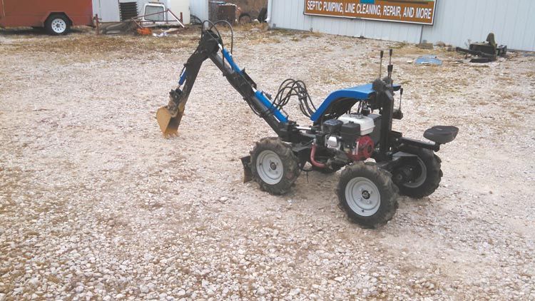
�����I found plans for a towable backhoe on the internet and modified it,� says Kincaid. �I wanted one that was self-propelled, but could get into tight spots and wouldn�t require a trailer.�
����Kincaid based his backhoe boom on plans from www.thegreensmachines.com. He used 1/4-in. steel plate for flat stock and 0.188 thick, 2 1/2-in. square tubing for the boom arms and chassis. The bucket is 7 in. wide with teeth cut from leaf springs. Kincaid bought the metal and had it cut and sheared locally.
����The motor sits on an I-shaped chassis made from 2 1/2-in. tubing with 1/4-in. plate gussets. A set of hydraulic drive wheels is mounted at either end. Two vertical tubes are mounted to the rear of the chassis. The forward one serves as a mount for control valves while the one to the rear is a mount for a removable seat.
����At the front of the chassis, the boom and its hydraulic cylinder are mounted to a yoke and swivel plate fabricated from 4 pieces of 3 by 5-in., 1/2-in. thick angle iron.
����A hydraulic cylinder extends from the chassis center frame to an offset mount on the swivel plate, swinging the boom to the left or right. Another short cylinder mounted to the front of the chassis raises and lowers a short blade he picked up at a garage sale. It works in lieu of outriggers.
�����A 5 hp Honda with a love joint to a 2 gpm hydraulic pump supplies power to the backhoe valve body and the drive wheels,� says Kincaid. �The wheels on each side run in series, so fluid goes to the first wheel and then to the second and then to the valve. It�s like a liquid chain.�
����Kincaid considered building a small trailer to tow the backhoe to job sites. Instead he decided to mount it on the front end of his truck. He extended the frame about 3 ft., providing more than enough space for the 32-in. wide backhoe.
����Kincaid estimates it took him 6 mo. to build the machine, initially with 2-WD. It took another week to make it 4-WD. Plans, steel, hydraulic hoses, cylinders, engine and other components totaled about $4,000.
Mini Backhoe Replaces Back-Breaking Shovel Work FENCING Miscellaneous Trinity Kincaid nicknamed his mini-backhoe �MyShovel� because of its ability to handle jobs large and small in Missouri hill country It replaced a lot of hand digging which he did plenty of while running his rural septic service �����I live and work at Lake of the Ozarks and the soil is clay and rock � he says �I used to use a pick axe or bar to break clods loose I even bought a small jackhammer � ����Kincaid considered buying a small excavator but he worried about finding parts for the limited production machines He finally decided to build his own �����I found plans for a towable backhoe on the internet and modified it � says Kincaid �I wanted one that was self-propelled but could get into tight spots and wouldn�t require a trailer � ����Kincaid based his backhoe boom on plans from www thegreensmachines com He used 1/4-in steel plate for flat stock and 0 188 thick 2 1/2-in square tubing for the boom arms and chassis The bucket is 7 in wide with teeth cut from leaf springs Kincaid bought the metal and had it cut and sheared locally �����Everything from the boom back is mine including the swivel � he says ����The motor sits on an I-shaped chassis made from 2 1/2-in tubing with 1/4-in plate gussets A set of hydraulic drive wheels is mounted at either end Two vertical tubes are mounted to the rear of the chassis The forward one serves as a mount for control valves while the one to the rear is a mount for a removable seat ����At the front of the chassis the boom and its hydraulic cylinder are mounted to a yoke and swivel plate fabricated from 4 pieces of 3 by 5-in 1/2-in thick angle iron �����I slipped them together and bolted them in place to be sure everything dovetailed together and slid and locked like needed � says Kincaid �Only then did I weld it together � ����A hydraulic cylinder extends from the chassis center frame to an offset mount on the swivel plate swinging the boom to the left or right Another short cylinder mounted to the front of the chassis raises and lowers a short blade he picked up at a garage sale It works in lieu of outriggers �����A 5 hp Honda with a love joint to a 2 gpm hydraulic pump supplies power to the backhoe valve body and the drive wheels � says Kincaid �The wheels on each side run in series so fluid goes to the first wheel and then to the second and then to the valve It�s like a liquid chain � ����Kincaid explains that if the wheels were moving at a high speed one would be turning faster than the other However at low speeds the second wheel is providing about 200 percent traction ����Kincaid considered building a small trailer to tow the backhoe to job sites Instead he decided to mount it on the front end of his truck He extended the frame about 3 ft providing more than enough space for the 32-in wide backhoe ����When he gets to the job site he backs it off the carrier puts the seat in place and drives it to the site of the septic tank When the dirt is removed he also uses the bucket to pick up lids which can weigh as much as 180 lbs �����You can do quite a bit with it if you�re patient � he says ����What it can�t do is easily break through a pipe which Kincaid appreciates �You�ll feel the pull on the machine before it can hurt a pipe � he says ����Kincaid estimates it took him 6 mo to build the machine initially with 2-WD It took another week to make it 4-WD Plans steel hydraulic hoses cylinders engine and other components totaled about $4 000 ����Buying local and looking for deals kept costs down �I found the wheel motors on sale for $200 each � he recalls �Normally they were priced at $600 I paid only $16 each for the wheel hubs at a surplus center but the regular price was $100 each � ����Kincaid is more than satisfied with the investment He has a boom that swings out with a reach of about 6 ft and a maximum depth of about 4 ft Each bucket is equivalent to about 3 spades full of dirt �����I can move a cubic yard of dirt in about 20 min � says Kincaid �By hand it would take about 2 hrs � ����Contact: FARM SHOW Followup Trinity Kincaid Kincaid Septic 22752 Hwy 5 Versailles Mo 65084 ph 573 216-7867; tk kincaidseptic@gmail com
This portable backhoe is powered by a high performance 9HP, 301cc Predator engine. It’s perfect for your landscaping projects including trenching, planting large trees, removing...

Hydraulic pumps are mechanisms in hydraulic systems that move hydraulic fluid from point to point initiating the production of hydraulic power. Hydraulic pumps are sometimes incorrectly referred to as “hydrolic” pumps.
They are an important device overall in the hydraulics field, a special kind of power transmission which controls the energy which moving fluids transmit while under pressure and change into mechanical energy. Other kinds of pumps utilized to transmit hydraulic fluids could also be referred to as hydraulic pumps. There is a wide range of contexts in which hydraulic systems are applied, hence they are very important in many commercial, industrial, and consumer utilities.
“Power transmission” alludes to the complete procedure of technologically changing energy into a beneficial form for practical applications. Mechanical power, electrical power, and fluid power are the three major branches that make up the power transmission field. Fluid power covers the usage of moving gas and moving fluids for the transmission of power. Hydraulics are then considered as a sub category of fluid power that focuses on fluid use in opposition to gas use. The other fluid power field is known as pneumatics and it’s focused on the storage and release of energy with compressed gas.
"Pascal"s Law" applies to confined liquids. Thus, in order for liquids to act hydraulically, they must be contained within a system. A hydraulic power pack or hydraulic power unit is a confined mechanical system that utilizes liquid hydraulically. Despite the fact that specific operating systems vary, all hydraulic power units share the same basic components. A reservoir, valves, a piping/tubing system, a pump, and actuators are examples of these components. Similarly, despite their versatility and adaptability, these mechanisms work together in related operating processes at the heart of all hydraulic power packs.
The hydraulic reservoir"s function is to hold a volume of liquid, transfer heat from the system, permit solid pollutants to settle, and aid in releasing moisture and air from the liquid.
Mechanical energy is changed to hydraulic energy by the hydraulic pump. This is accomplished through the movement of liquid, which serves as the transmission medium. All hydraulic pumps operate on the same basic principle of dispensing fluid volume against a resistive load or pressure.
Hydraulic valves are utilized to start, stop, and direct liquid flow in a system. Hydraulic valves are made of spools or poppets and can be actuated hydraulically, pneumatically, manually, electrically, or mechanically.
The end result of Pascal"s law is hydraulic actuators. This is the point at which hydraulic energy is transformed back to mechanical energy. This can be accomplished by using a hydraulic cylinder to transform hydraulic energy into linear movement and work or a hydraulic motor to transform hydraulic energy into rotational motion and work. Hydraulic motors and hydraulic cylinders, like hydraulic pumps, have various subtypes, each meant for specific design use.
The essence of hydraulics can be found in a fundamental physical fact: fluids are incompressible. (As a result, fluids more closely resemble solids than compressible gasses) The incompressible essence of fluid allows it to transfer force and speed very efficiently. This fact is summed up by a variant of "Pascal"s Principle," which states that virtually all pressure enforced on any part of a fluid is transferred to every other part of the fluid. This scientific principle states, in other words, that pressure applied to a fluid transmits equally in all directions.
Furthermore, the force transferred through a fluid has the ability to multiply as it moves. In a slightly more abstract sense, because fluids are incompressible, pressurized fluids should keep a consistent pressure just as they move. Pressure is defined mathematically as a force acting per particular area unit (P = F/A). A simplified version of this equation shows that force is the product of area and pressure (F = P x A). Thus, by varying the size or area of various parts inside a hydraulic system, the force acting inside the pump can be adjusted accordingly (to either greater or lesser). The need for pressure to remain constant is what causes force and area to mirror each other (on the basis of either shrinking or growing). A hydraulic system with a piston five times larger than a second piston can demonstrate this force-area relationship. When a force (e.g., 50lbs) is exerted on the smaller piston, it is multiplied by five (e.g., 250 lbs) and transmitted to the larger piston via the hydraulic system.
Hydraulics is built on fluids’ chemical properties and the physical relationship between pressure, area, and force. Overall, hydraulic applications allow human operators to generate and exert immense mechanical force with little to no physical effort. Within hydraulic systems, both oil and water are used to transmit power. The use of oil, on the other hand, is far more common, owing in part to its extremely incompressible nature.
Pressure relief valves prevent excess pressure by regulating the actuators’ output and redirecting liquid back to the reservoir when necessary. Directional control valves are used to change the size and direction of hydraulic fluid flow.
While hydraulic power transmission is remarkably useful in a wide range of professional applications, relying solely on one type of power transmission is generally unwise. On the contrary, the most efficient strategy is to combine a wide range of power transmissions (pneumatic, hydraulic, mechanical, and electrical). As a result, hydraulic systems must be carefully embedded into an overall power transmission strategy for the specific commercial application. It is necessary to invest in locating trustworthy and skilled hydraulic manufacturers/suppliers who can aid in the development and implementation of an overall hydraulic strategy.
The intended use of a hydraulic pump must be considered when selecting a specific type. This is significant because some pumps may only perform one function, whereas others allow for greater flexibility.
The pump"s material composition must also be considered in the application context. The cylinders, pistons, and gears are frequently made of long-lasting materials like aluminum, stainless steel, or steel that can withstand the continuous wear of repeated pumping. The materials must be able to withstand not only the process but also the hydraulic fluids. Composite fluids frequently contain oils, polyalkylene glycols, esters, butanol, and corrosion inhibitors (though water is used in some instances). The operating temperature, flash point, and viscosity of these fluids differ.
In addition to material, manufacturers must compare hydraulic pump operating specifications to make sure that intended utilization does not exceed pump abilities. The many variables in hydraulic pump functionality include maximum operating pressure, continuous operating pressure, horsepower, operating speed, power source, pump weight, and maximum fluid flow. Standard measurements like length, rod extension, and diameter should be compared as well. Because hydraulic pumps are used in lifts, cranes, motors, and other heavy machinery, they must meet strict operating specifications.
It is critical to recall that the overall power generated by any hydraulic drive system is influenced by various inefficiencies that must be considered in order to get the most out of the system. The presence of air bubbles within a hydraulic drive, for example, is known for changing the direction of the energy flow inside the system (since energy is wasted on the way to the actuators on bubble compression). Using a hydraulic drive system requires identifying shortfalls and selecting the best parts to mitigate their effects. A hydraulic pump is the "generator" side of a hydraulic system that initiates the hydraulic procedure (as opposed to the "actuator" side that completes the hydraulic procedure). Regardless of disparities, all hydraulic pumps are responsible for displacing liquid volume and transporting it to the actuator(s) from the reservoir via the tubing system. Some form of internal combustion system typically powers pumps.
While the operation of hydraulic pumps is normally the same, these mechanisms can be split into basic categories. There are two types of hydraulic pumps to consider: gear pumps and piston pumps. Radial and axial piston pumps are types of piston pumps. Axial pumps produce linear motion, whereas radial pumps can produce rotary motion. The gear pump category is further subdivided into external gear pumps and internal gear pumps.
Each type of hydraulic pump, regardless of piston or gear, is either double-action or single-action. Single-action pumps can only pull, push, or lift in one direction, while double-action pumps can pull, push, or lift in multiple directions.
Vane pumps are positive displacement pumps that maintain a constant flow rate under varying pressures. It is a pump that self-primes. It is referred to as a "vane pump" because the effect of the vane pressurizes the liquid.
This pump has a variable number of vanes mounted onto a rotor that rotates within the cavity. These vanes may be variable in length and tensioned to maintain contact with the wall while the pump draws power. The pump also features a pressure relief valve, which prevents pressure rise inside the pump from damaging it.
Internal gear pumps and external gear pumps are the two main types of hydraulic gear pumps. Pumps with external gears have two spur gears, the spurs of which are all externally arranged. Internal gear pumps also feature two spur gears, and the spurs of both gears are internally arranged, with one gear spinning around inside the other.
Both types of gear pumps deliver a consistent amount of liquid with each spinning of the gears. Hydraulic gear pumps are popular due to their versatility, effectiveness, and fairly simple design. Furthermore, because they are obtainable in a variety of configurations, they can be used in a wide range of consumer, industrial, and commercial product contexts.
Hydraulic ram pumps are cyclic machines that use water power, also referred to as hydropower, to transport water to a higher level than its original source. This hydraulic pump type is powered solely by the momentum of moving or falling water.
Ram pumps are a common type of hydraulic pump, especially among other types of hydraulic water pumps. Hydraulic ram pumps are utilized to move the water in the waste management, agricultural, sewage, plumbing, manufacturing, and engineering industries, though only about ten percent of the water utilized to run the pump gets to the planned end point.
Despite this disadvantage, using hydropower instead of an external energy source to power this kind of pump makes it a prominent choice in developing countries where the availability of the fuel and electricity required to energize motorized pumps is limited. The use of hydropower also reduces energy consumption for industrial factories and plants significantly. Having only two moving parts is another advantage of the hydraulic ram, making installation fairly simple in areas with free falling or flowing water. The water amount and the rate at which it falls have an important effect on the pump"s success. It is critical to keep this in mind when choosing a location for a pump and a water source. Length, size, diameter, minimum and maximum flow rates, and speed of operation are all important factors to consider.
Hydraulic water pumps are machines that move water from one location to another. Because water pumps are used in so many different applications, there are numerous hydraulic water pump variations.
Water pumps are useful in a variety of situations. Hydraulic pumps can be used to direct water where it is needed in industry, where water is often an ingredient in an industrial process or product. Water pumps are essential in supplying water to people in homes, particularly in rural residences that are not linked to a large sewage circuit. Water pumps are required in commercial settings to transport water to the upper floors of high rise buildings. Hydraulic water pumps in all of these situations could be powered by fuel, electricity, or even by hand, as is the situation with hydraulic hand pumps.
Water pumps in developed economies are typically automated and powered by electricity. Alternative pumping tools are frequently used in developing economies where dependable and cost effective sources of electricity and fuel are scarce. Hydraulic ram pumps, for example, can deliver water to remote locations without the use of electricity or fuel. These pumps rely solely on a moving stream of water’s force and a properly configured number of valves, tubes, and compression chambers.
Electric hydraulic pumps are hydraulic liquid transmission machines that use electricity to operate. They are frequently used to transfer hydraulic liquid from a reservoir to an actuator, like a hydraulic cylinder. These actuation mechanisms are an essential component of a wide range of hydraulic machinery.
There are several different types of hydraulic pumps, but the defining feature of each type is the use of pressurized fluids to accomplish a job. The natural characteristics of water, for example, are harnessed in the particular instance of hydraulic water pumps to transport water from one location to another. Hydraulic gear pumps and hydraulic piston pumps work in the same way to help actuate the motion of a piston in a mechanical system.
Despite the fact that there are numerous varieties of each of these pump mechanisms, all of them are powered by electricity. In such instances, an electric current flows through the motor, which turns impellers or other devices inside the pump system to create pressure differences; these differential pressure levels enable fluids to flow through the pump. Pump systems of this type can be utilized to direct hydraulic liquid to industrial machines such as commercial equipment like elevators or excavators.
Hydraulic hand pumps are fluid transmission machines that utilize the mechanical force generated by a manually operated actuator. A manually operated actuator could be a lever, a toggle, a handle, or any of a variety of other parts. Hydraulic hand pumps are utilized for hydraulic fluid distribution, water pumping, and various other applications.
Hydraulic hand pumps may be utilized for a variety of tasks, including hydraulic liquid direction to circuits in helicopters and other aircraft, instrument calibration, and piston actuation in hydraulic cylinders. Hydraulic hand pumps of this type use manual power to put hydraulic fluids under pressure. They can be utilized to test the pressure in a variety of devices such as hoses, pipes, valves, sprinklers, and heat exchangers systems. Hand pumps are extraordinarily simple to use.
Each hydraulic hand pump has a lever or other actuation handle linked to the pump that, when pulled and pushed, causes the hydraulic liquid in the pump"s system to be depressurized or pressurized. This action, in the instance of a hydraulic machine, provides power to the devices to which the pump is attached. The actuation of a water pump causes the liquid to be pulled from its source and transferred to another location. Hydraulic hand pumps will remain relevant as long as hydraulics are used in the commerce industry, owing to their simplicity and easy usage.
12V hydraulic pumps are hydraulic power devices that operate on 12 volts DC supplied by a battery or motor. These are specially designed processes that, like all hydraulic pumps, are applied in commercial, industrial, and consumer places to convert kinetic energy into beneficial mechanical energy through pressurized viscous liquids. This converted energy is put to use in a variety of industries.
Hydraulic pumps are commonly used to pull, push, and lift heavy loads in motorized and vehicle machines. Hydraulic water pumps may also be powered by 12V batteries and are used to move water out of or into the desired location. These electric hydraulic pumps are common since they run on small batteries, allowing for ease of portability. Such portability is sometimes required in waste removal systems and vehiclies. In addition to portable and compact models, options include variable amp hour productions, rechargeable battery pumps, and variable weights.
While non rechargeable alkaline 12V hydraulic pumps are used, rechargeable ones are much more common because they enable a continuous flow. More considerations include minimum discharge flow, maximum discharge pressure, discharge size, and inlet size. As 12V batteries are able to pump up to 150 feet from the ground, it is imperative to choose the right pump for a given use.
Air hydraulic pumps are hydraulic power devices that use compressed air to stimulate a pump mechanism, generating useful energy from a pressurized liquid. These devices are also known as pneumatic hydraulic pumps and are applied in a variety of industries to assist in the lifting of heavy loads and transportation of materials with minimal initial force.
Air pumps, like all hydraulic pumps, begin with the same components. The hydraulic liquids, which are typically oil or water-based composites, require the use of a reservoir. The fluid is moved from the storage tank to the hydraulic cylinder via hoses or tubes connected to this reservoir. The hydraulic cylinder houses a piston system and two valves. A hydraulic fluid intake valve allows hydraulic liquid to enter and then traps it by closing. The discharge valve is the point at which the high pressure fluid stream is released. Air hydraulic pumps have a linked air cylinder in addition to the hydraulic cylinder enclosing one end of the piston.
The protruding end of the piston is acted upon by a compressed air compressor or air in the cylinder. When the air cylinder is empty, a spring system in the hydraulic cylinder pushes the piston out. This makes a vacuum, which sucks fluid from the reservoir into the hydraulic cylinder. When the air compressor is under pressure, it engages the piston and pushes it deeper into the hydraulic cylinder and compresses the liquids. This pumping action is repeated until the hydraulic cylinder pressure is high enough to forcibly push fluid out through the discharge check valve. In some instances, this is connected to a nozzle and hoses, with the important part being the pressurized stream. Other uses apply the energy of this stream to pull, lift, and push heavy loads.
Hydraulic piston pumps transfer hydraulic liquids through a cylinder using plunger-like equipment to successfully raise the pressure for a machine, enabling it to pull, lift, and push heavy loads. This type of hydraulic pump is the power source for heavy-duty machines like excavators, backhoes, loaders, diggers, and cranes. Piston pumps are used in a variety of industries, including automotive, aeronautics, power generation, military, marine, and manufacturing, to mention a few.
Hydraulic piston pumps are common due to their capability to enhance energy usage productivity. A hydraulic hand pump energized by a hand or foot pedal can convert a force of 4.5 pounds into a load-moving force of 100 pounds. Electric hydraulic pumps can attain pressure reaching 4,000 PSI. Because capacities vary so much, the desired usage pump must be carefully considered. Several other factors must also be considered. Standard and custom configurations of operating speeds, task-specific power sources, pump weights, and maximum fluid flows are widely available. Measurements such as rod extension length, diameter, width, and height should also be considered, particularly when a hydraulic piston pump is to be installed in place of a current hydraulic piston pump.
Hydraulic clutch pumps are mechanisms that include a clutch assembly and a pump that enables the user to apply the necessary pressure to disengage or engage the clutch mechanism. Hydraulic clutches are crafted to either link two shafts and lock them together to rotate at the same speed or detach the shafts and allow them to rotate at different speeds as needed to decelerate or shift gears.
Hydraulic pumps change hydraulic energy to mechanical energy. Hydraulic pumps are particularly designed machines utilized in commercial, industrial, and residential areas to generate useful energy from different viscous liquids pressurization. Hydraulic pumps are exceptionally simple yet effective machines for moving fluids. "Hydraulic" is actually often misspelled as "Hydralic". Hydraulic pumps depend on the energy provided by hydraulic cylinders to power different machines and mechanisms.
There are several different types of hydraulic pumps, and all hydraulic pumps can be split into two primary categories. The first category includes hydraulic pumps that function without the assistance of auxiliary power sources such as electric motors and gas. These hydraulic pump types can use the kinetic energy of a fluid to transfer it from one location to another. These pumps are commonly called ram pumps. Hydraulic hand pumps are never regarded as ram pumps, despite the fact that their operating principles are similar.
The construction, excavation, automotive manufacturing, agriculture, manufacturing, and defense contracting industries are just a few examples of operations that apply hydraulics power in normal, daily procedures. Since hydraulics usage is so prevalent, hydraulic pumps are unsurprisingly used in a wide range of machines and industries. Pumps serve the same basic function in all contexts where hydraulic machinery is used: they transport hydraulic fluid from one location to another in order to generate hydraulic energy and pressure (together with the actuators).
Elevators, automotive brakes, automotive lifts, cranes, airplane flaps, shock absorbers, log splitters, motorboat steering systems, garage jacks and other products use hydraulic pumps. The most common application of hydraulic pumps in construction sites is in big hydraulic machines and different types of "off-highway" equipment such as excavators, dumpers, diggers, and so on. Hydraulic systems are used in other settings, such as offshore work areas and factories, to power heavy machinery, cut and bend material, move heavy equipment, and so on.
Fluid’s incompressible nature in hydraulic systems allows an operator to make and apply mechanical power in an effective and efficient way. Practically all force created in a hydraulic system is applied to the intended target.
Because of the relationship between area, pressure, and force (F = P x A), modifying the force of a hydraulic system is as simple as changing the size of its components.
Hydraulic systems can transfer energy on an equal level with many mechanical and electrical systems while being significantly simpler in general. A hydraulic system, for example, can easily generate linear motion. On the contrary, most electrical and mechanical power systems need an intermediate mechanical step to convert rotational motion to linear motion.
Hydraulic systems are typically smaller than their mechanical and electrical counterparts while producing equivalents amounts of power, providing the benefit of saving physical space.
Hydraulic systems can be used in a wide range of physical settings due to their basic design (a pump attached to actuators via some kind of piping system). Hydraulic systems could also be utilized in environments where electrical systems would be impractical (for example underwater).
By removing electrical safety hazards, using hydraulic systems instead of electrical power transmission improves relative safety (for example explosions, electric shock).
The amount of power that hydraulic pumps can generate is a significant, distinct advantage. In certain cases, a hydraulic pump could generate ten times the power of an electrical counterpart. Some hydraulic pumps (for example, piston pumps) cost more than the ordinary hydraulic component. These drawbacks, however, can be mitigated by the pump"s power and efficiency. Despite their relatively high cost, piston pumps are treasured for their strength and capability to transmit very viscous fluids.
Handling hydraulic liquids is messy, and repairing leaks in a hydraulic pump can be difficult. Hydraulic liquid that leaks in hot areas may catch fire. Hydraulic lines that burst may cause serious injuries. Hydraulic liquids are corrosive as well, though some are less so than others. Hydraulic systems need frequent and intense maintenance. Parts with a high factor of precision are frequently required in systems. If the power is very high and the pipeline cannot handle the power transferred by the liquid, the high pressure received by the liquid may also cause work accidents.
Even though hydraulic systems are less complex than electrical or mechanical systems, they are still complex systems that should be handled with caution. Avoiding physical contact with hydraulic systems is an essential safety precaution when engaging with them. Even when a hydraulic machine is not in use, active liquid pressure within the system can be a hazard.
Inadequate pumps can cause mechanical failure in the place of work that can have serious and costly consequences. Although pump failure has historically been unpredictable, new diagnostic technology continues to improve on detecting methods that previously relied solely on vibration signals. Measuring discharge pressures enables manufacturers to forecast pump wear more accurately. Discharge sensors are simple to integrate into existing systems, increasing the hydraulic pump"s safety and versatility.
Hydraulic pumps are devices in hydraulic systems that move hydraulic fluid from point to point, initiating hydraulic power production. They are an important device overall in the hydraulics field, a special kind of power transmission that controls the energy which moving fluids transmit while under pressure and change into mechanical energy. Hydraulic pumps are divided into two categories namely gear pumps and piston pumps. Radial and axial piston pumps are types of piston pumps. Axial pumps produce linear motion, whereas radial pumps can produce rotary motion. The construction, excavation, automotive manufacturing, agriculture, manufacturing, and defense contracting industries are just a few examples of operations that apply hydraulics power in normal, daily procedures.

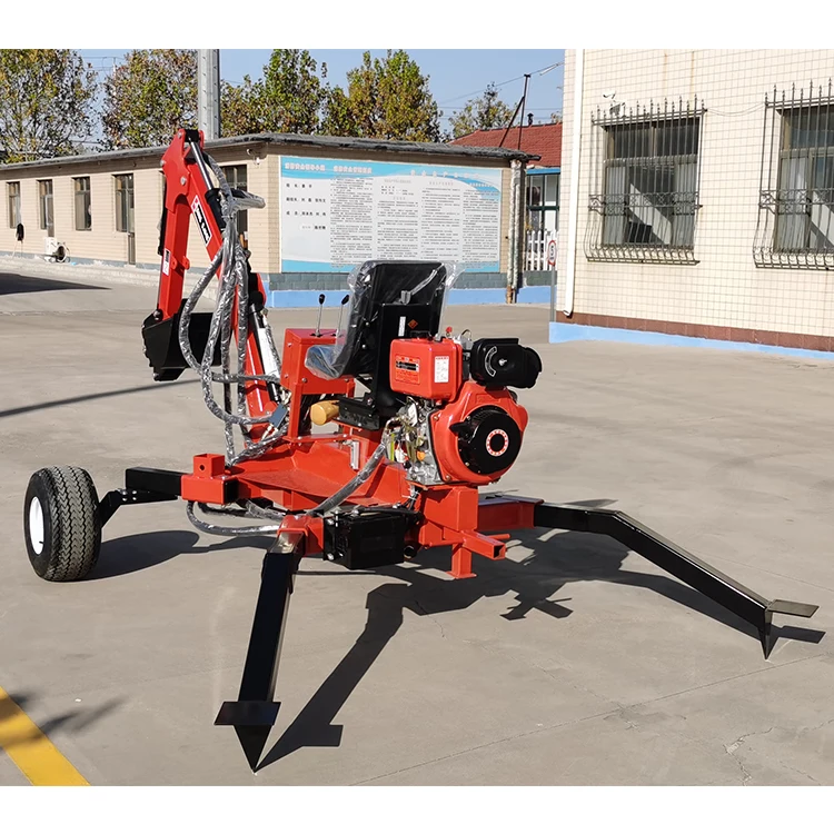
The 14.5 FPT DR Towable Backhoe has power to spare for trenching, landscaping, stump removal, heavy lifting and more. Designed especially for the most demanding digging tasks, this machine is self-powered with its own hydraulic system, so there’s no fussing with a 3-point hitch or hydraulic connections.

I live in southern Alberta, Canada. I had Jansen USA ship the purchased backhoe to a Montana shipping warehouse. It was stored there until I drove down with a trailer to pick it up. Three warehouse lads and a dollie helped me lift the large wooden box it comes in into the trailer. At the Canadian customs crossing the officers charged me GST on the purchase price (remember to take your payment receipt with you). Other Canadian provinces will charge PST as well. There was no foreign duty.
This machine is a workhorse. I bought it to renovate an old road on my property; however, once the backhoe was operational I found all sorts of other jobs for it to do including crudely leveling my back yard for a brick patio, creating a ramp to the front door, and digging out a compost pit. It has also been towed to a friend’s garden to do work there. I bought the unit in March 2020 (just before the border closed) and it has been heavily used during the months the ground wasn’t frozen. It is now November 2021 and I am finishing up the old road. If the backhoe is moving itself forward I sit on the seat to drive it. When doing a stationary job, such as filling wheelbarrows, I often stand beside the seat and operate it from the side. When working in the hot sun, I attached a flexible camp chair umbrella to the backhoe seat for shade. I made wooden shoes for the foot spikes when walking the machine across my asphalt driveway.
The machine has been used a lot and I have had to replace a few nuts and an hydraulic hose as they wore out. They were a standard size and easy to find at the local hardware store. Important points to remember are to replace the hydraulic fluid periodically and lubricate moving parts, as suggested in the manual.

This monoblock valve is a hydraulic directional control valve. These valves are used to start and stop fluid flow into hydraulic cylinders or hydraulic motors.
Is the flow through this valve less than 11 GPM? If not, then we have largertractor-data.com, it will say under the hydraulics – “Pump Flow” – of the data sheet. The GPM flow may be printed on the pump itself.
Do you have an open-center hydraulic system? If you’re installing this on a tractor please check tractor-data.com, it will say under the hydraulics of the data sheet. These valves are setup for use on open-center hydraulic systems. If you do have a closed-center system you’ll need to get the NOTE: None of our valves have load-sensing capabilities.
Do you have other valves downstream from this valve (Examples include: Other Control Valves, Rear Remote Valve, Backhoe Valve, 3-Point Valve)? If so, you’ll need the Note: This is only needed on open-center hydraulic systems. If you have a closed-center system, you will tee into a pressure line to connect other valves.
Are you operating a hydraulic cylinder or a hydraulic motor?If you’re operating a hydraulic cylinder you’ll need to get “A” spools for double acting cylinders, if you’re operating a hydraulic motor you’ll need “D” spools for motor control. Note: “D” spools cannot be used for operating hydraulic cylinders and “A” spools cannot be used to operate hydraulic motors.
This valve has a pressure line (Inlet), tank line (outlet), work ports (A/B ports that go to hydraulic cylinder or motor), and optional power beyond port (N Port, used to connect valves downstream). Some common examples of connecting this valve below, however it is possible to connect it in different configurations than shown.


 8613371530291