
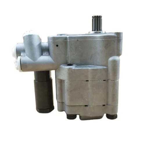
tractor auxiliary hydraulic pump free sample
The present invention relates generally to auxiliary hydraulic systems for working vehicles. In particular, the present invention relates to a control system for an auxiliary hydraulic system, the control system including an operator control console including control levers and maximum flow control devices.
Working vehicles often include auxiliary hydraulic systems configured to supply pressurized hydraulic fluid from a vehicle hydraulic pump to auxiliary equipment or attachments. For example, agricultural and construction equipment vehicles (e.g., tractors; tractor-loaders; skid-steer loaders) may be coupled to attachments such as augers, grapples, sweepers, landscape rakes, backhoes, scarfers, snowblowers, stabilizers, raising and lowering implements or other attachments driven by hydraulic actuators such as hydraulic cylinders or hydraulic motors.
The attachments can be referred to as "auxiliary" equipment since they are typically connected to a vehicle to perform a particular job, and then disconnected when the job is complete. Accordingly, the working vehicles include external fluid fittings to facilitate connecting and disconnecting the hydraulic fluid supply lines of the attachments to the vehicles" auxiliary hydraulic systems. The auxiliary hydraulic systems include valves configured to control the supply of hydraulic fluid flowing through the fittings. The use of auxiliary equipment increases versatility of working vehicles by allowing the vehicles to perform different functions at different times.
Different attachments impose varying requirements on auxiliary hydraulic systems with respect to timing, rate and control of fluid flow. For example, an attachment equipped with a hydraulic motor (e.g., auger) may require a continuous flow of fluid while an attachment equipped with a hydraulic cylinder actuator (e.g., plow) may only require a flow of fluid for a discrete period. A desired rate of flow may depend upon the weight of an implement or on the work being performed by an attachment. For example, the flow rate required to raise an implement at a desired speed (e.g., fast enough for efficiency yet slow enough for safety) may be higher for a relatively heavy implement than for a relatively light implement. Closed-loop control based upon feedback signals may or may not be required. For example, a plow can be raised and lowered between desired raise and lower positions by a hydraulic cylinder actuator based on position feedback signals while a landscape rake may be raised or lowered by applying a fluid flow for a period sufficient to fully raise or lower the rake. Further, an auxiliary hydraulic system may be required to supply fluid to an attachment at a maximum flow rate in some situations and at a "feathered" flow rate (e.g., proportional control) in other situations such as during precision operations.
An auxiliary hydraulic system may also be required to provide hydraulic fluid flows to a number of auxiliary attachments having different fluid flow timing, rate and control requirements. For example, a tractor could be required to provide hydraulic fluid to simultaneously raise and lower a plow based upon position feedback signals, raise and lower a rake, and drive an auger.
Accordingly, it would be advantageous to provide an improved auxiliary hydraulic system capable of providing pressurized fluid to attachments in continuous or timed modes, of providing fluid to attachments at flow rates which can be set by an operator, of providing fluid to certain attachments using closed-loop control based upon feedback signals, and of providing fluid to attachments at maximum or feathered flow rates. Further, it would be advantageous to provide an improved auxiliary hydraulic system for supplying pressurized fluid to attachments having varying timing, rate and control requirements.
It would also be advantageous to provide an improved operator control console for a working vehicle equipped with an auxiliary hydraulic system. Advantages which can be realized by the improved operator control console disclosed herein include the versatility to provide fluid flow command signals for attachments with varying timing, rate and control requirements. The command signals can be used to control different types of attachments which may be coupled to auxiliary hydraulic systems. Further, the operator control console provides flow limit input devices to allow an operator to set maximum flow rates for each auxiliary valve within the system. The operator control console includes an interface for communication across a vehicle databus.
One embodiment of the invention provides an operator control console for a working vehicle equipped with an auxiliary hydraulic system including a fluid pump, a plurality of fittings, an auxiliary valve assembly for controlling the flow of fluid between the fluid pump and the fittings in response to control signals, and an auxiliary control circuit for receiving command signals and generating the control signals therefrom. The operator control console includes a console cover, and at least one control lever extending above the console cover and moveable between a plurality of positions including neutral and maximum flow positions. The operator control console further includes a sensing circuit for generating a signal representative of the position of the control lever, at least one flow limit input device including a handle extending above the console cover and configured to generate a signal representative of a flow limit, and a console control circuit coupled to the sensing circuit and the flow limit input device. The console control circuit is configured to generate the command signals to correspond to a flow rate between a neutral flow rate and the flow limit depending upon the position of the control lever.
Another embodiment of the invention provides an auxiliary hydraulic system for a working vehicle having an operator station. The auxiliary hydraulic system includes a hydraulic pump supported by the vehicle for providing hydraulic fluid under pressure, a plurality of auxiliary hydraulic fittings configured to be connected to auxiliary attachments, a plurality of electrically-actuated auxiliary valve assemblies configured to control the supply of hydraulic fluid from the pump to the auxiliary hydraulic fittings in response to control signals, and an operator control console mounted at the operator station. The control console includes a console cover, and a plurality of control levers extending above the console cover and moveable between a plurality of positions including neutral and maximum flow positions. The control console further includes a plurality of sensing circuits, each sensing circuit coupled to one of the control levers for generating a signal representative of the position of the respective control lever, a plurality of flow limit input devices, each flow limit input device including a handle extending above the console cover and configured to generate a signal representative of a flow limit for one of the valve assemblies, and a console control circuit coupled to the sensing circuits and the flow limit input devices. The console control circuit is configured to generate command signals for each valve assembly which correspond to a flow rate between a neutral flow rate and the flow limit for the respective valve assembly depending upon the position of the respective control lever. The auxiliary hydraulic system further includes an auxiliary control circuit coupled to the auxiliary valve assemblies and the operator control console. The auxiliary control circuit is configured to receive the command signals and to generate the control signals therefrom, and to apply the control signals to the valve assemblies, whereby the supply of hydraulic fluid to the auxiliary valve fittings depends upon the positions of the control levers and the flow limits.
FIG. 1 is a block diagram representing a working vehicle equipped with an auxiliary hydraulic system for supplying pressurized hydraulic fluid to attachments, the auxiliary hydraulic system including an armrest control unit, an auxiliary control unit and auxiliary valves;
FIG. 2 is a perspective view of the armrest control unit of FIG. 1 which shows command devices for the auxiliary hydraulic system including valve control lever assemblies with kick-out timer disable switches, a valve control switch, flow limit control knobs, a kick-out timer set knob, and an extend/retract limit switch;
FIG. 6 shows scaling performed by the processing circuit of the armrest control unit to generate command signals from the auxiliary valve control lever positions;
FIG. 7 shows scaling performed by the processing circuit of the armrest control unit to generate command signals from the auxiliary flow limit control knobs and the automatic kick-out timer set knob;
FIG. 12 is a block diagram of an instrumentation control unit (ICU) used for providing an operator input and output interface during calibration and configuration of the auxiliary hydraulic system and other systems; and
Referring to FIG. 1, a working vehicle 10 is equipped with an auxiliary hydraulic system 12 for supplying pressurized hydraulic fluid to attachments 14-22. Working vehicle 10 can be an agricultural or construction equipment vehicle and attachments 14-22 include hydraulic actuators having independent hydraulic fluid flow timing, rate and control requirements.
Auxiliary hydraulic system 12 includes an armrest control unit 24, an auxiliary control unit 26 and auxiliary valve assemblies 28-36. Armrest control unit 24 is mounted at an operator station of the vehicle (e.g., cab) and includes various input or command devices 38 configured to generate electrical command signals. Command devices 38 include valve control levers 40-46 for controlling the flow of fluid through auxiliary valve assemblies 28-34, respectively, a valve control switch 48 for controlling the flow through auxiliary valve assembly 36, automatic kick-out timer disable switches 50-56 for disabling an automatic kick-out function for valve assemblies 28-34, flow limit control knobs 58-66 for setting flow limits for valve assemblies 28-36, a kick-out timer set knob 68 for setting an automatic kick-out time period for valve assemblies 28-36, and an extend and retract limit switch 70 for setting extend/retract limits for attachment 14.
Auxiliary control unit 26 receives the command signals from bus 72, generates valve control signals on conductors 74-82 from the command signals, and applies the control signals via conductors 74-82 to valve assemblies 28-36. Valve assemblies 28-36 also receive a flow of pressurized hydraulic fluid from a source 84 (e.g., a pump) via fluid hoses or conduits 86, and supply a flow of pressurized fluid to each auxiliary hydraulic fitting 88-96 via hoses 98-106 in response to the control signals on conductors 74-82. Auxiliary hydraulic fittings 88-96 are configured for easy connection and disconnection to attachments 14-22. The fluid supply network between auxiliary hydraulic system 12 and attachments 14-22 can have other configurations such as using multiple hoses for each attachment.
In one embodiment, each auxiliary valve assembly 28-36 includes a stepper motor, a valve interface or backcap operated by the stepper motor and a valve fluidly coupled between source 84 and the respective fitting 88-96.
The stepper motors receive power and control signals 74-82 from auxiliary control unit 26. Each stepper motor includes a rotor driven by two direct current (DC) phases or coils controlled by four control lines. The rotor is rotated in steps (e.g., 1/4 revolution/step) in either direction in response to changes in the polarity of the coils. The number of steps needed for the valve to reach a desired valve position is controlled by a stepper motor controller (FIG. 8) in response to the command signals from armrest control unit 24.
Auxiliary control unit 26 receives electrical power from the vehicle battery through an ignition key switch 108 and a fuse 110. Auxiliary control unit 26 may also receive a feedback signal via line 112 from an optional sensor 114 coupled to attachment 14. Sensor 114 may be, for example, a cylinder position sensor (e.g., LVDT or potentiometer) configured to sense the position of a hydraulic cylinder in attachment 14. Feedback signal 112 can be used by auxiliary control unit 26 as a control input in a cylinder position mode of operation wherein the fluid flow is controlled to move a cylinder between extend and retract positions set by limit switch 70.
The high degree of integration of command devices 38 in armrest control unit 24 provides a convenient and inexpensive operator interface to the various control systems of vehicle 10. For example, an operator can fully control auxiliary hydraulic system 12 from a single console, and the expense and inconvenience associated with additional control panels are avoided.
Processing circuit 266 also scales the filtered analog readings 302 and transmits the scaled values in the outgoing data bus messages. The scaling provides accurate command signals even if relatively low accuracy potentiometers are used. The scaling of the filtered analog readings 302 for auxiliary valve control levers 40-46 is shown in FIG. 6.
Referring to FIG. 8, auxiliary control unit 26 includes an interface circuit 330 for transmitting and receiving messages via bus 72, a processing circuit 332 for generating stepper motor control data 334-342 in response to the command signals from armrest control unit 24, stepper motor controllers 344-352 for generating control signals 354-362 for the stepper motors, and H-bridge driver circuits 364-372 for generating valve control signals 74-82 for valve assemblies 28-36. A memory circuit 374 may include volatile (e.g., RAM) and non-volatile (e.g., ROM, EEROM) memory. Processing circuit 332 also receives optional feedback signal 112 and a power signal from key switch 108.
Interface circuit 330 includes bus controller (e.g., an 82527) and CAN transceiver (e.g., 82C250) circuits for communication via bus 72. Processing and memory circuits 332 and 374 include a processor circuit (e.g., a 80C198 microcontroller) and a combination interface circuit (e.g., PSD312). Each stepper motor controller 344-352 includes an L297 circuit, and each H-bridge driver circuit 364-372 includes two L6203 drivers (one L6203 driver for each stepper motor phase). Auxiliary control unit 26 generates valve control signals 74-82 for moving the respective valve to the desired valve position.
Referring to FIGS. 9A-9C, processing circuit 332 is programmed to control auxiliary valve assemblies 28-36 in one of several valve states. The desired valve state is determined during background processing. After the desired valve state is determined, control signals 74-82 are updated and strobed to valve assemblies 28-36 during foreground processing triggered on a time basis. Valve assemblies 28-34 are controlled in the following states:
In process 408, processing circuit 332 handles background auxiliary functions (described in relation to FIG. 9B) to update valve states 404, extend and retract set points 406, valve flow rates 410 and valve target positions 412 in response to incoming messages from bus 72 which contain the command signals from armrest control unit 24. In foreground process 414, processing circuit 332 generates stepper motor control signals 334-342 in response to flow rates 410 and target positions 412.
In operation, an operator independently controls the flow of hydraulic fluid through auxiliary valves 1-4 in one of several modes selected using arm 224 to rotate guide 208. Then, the respective control lever 40-46 is moved to a flow command position within an allowed range. For valve 5, the flow rate is controlled using switch 48. Maximum flow rate through each valve is set independently using flow limit control knobs 58-66. Using detent and feel lever positions, flow rates are commanded for valves 1-4 which correspond to a maximum extend flow rate, a proportional extend flow rate, a neutral flow rate, a proportional retract flow rate and a maximum retract flow rate. An operator can also select a float valve position wherein the valve spool is positioned such that there is no forced flow in either direction. In float position, the attachment may, for example, move up or down with the ground, or move down by the force of gravity. For valve 5, the operator can command a maximum extend flow rate, a neutral flow rate, and a maximum retract flow rate.
Typically, the maximum extend and maximum retract flow rates continue for a predetermined time period after the respective control lever is moved into the extend detent or raise detent position (or extend or retract switch position). After this time period, an automatic kick-out occurs and the flow drops to neutral (i.e., 0 flow). The automatic kick-out prevents the system from remaining in "high standby" status and robbing the system of power when, for example, a hydraulic cylinder has already reached a desired position Typically, the kick-out time period will be set using knob 68 to supply flow for a time period (e.g., 10 sec) longer than the time required to move the slowest attachment (e.g., 8 sec).
If the control lever moves out of the extend detent or retract detent position before a kick-out occurs, the timer is reset and flow rate follows the control lever proportionately. If the control lever is not moved until after a kick-out occurs, the control lever must be first moved to the neutral position before the flow rate can be controlled again. In addition, if guide 208 of control lever assembly 160 is moved into the "MOTOR" position, the automatic kick-out function is disabled and the flow continues indefinitely. MOTOR position, then, is used for hydraulic motors which require continuous flow.
Therefore, auxiliary hydraulic system 12 calibrates control levers 40-46 and generates calibrated command signals. The calibration involves moving each control lever 40-46 into the extend detent and retract detent positions, converting the resulting position signals sensed by potentiometer 238 into extend and retract calibration values, and storing the calibration values in EEPROM as in the memory map shown in FIG. 11. CAL-- AUXn-- EXTEND and CAL-- AUXn-- RETRACT correspond to the digitized readings when the nth control lever (n=1 to 4) is moved into the extend detent and retract detent positions, respectively, during a calibration procedure.
Referring to FIG. 12, calibration of auxiliary hydraulic system 12 and of other systems connected to bus 72 is controlled by an instrumentation control unit (ICU) 500. ICU 500 includes an ICU control circuit 502, an interface circuit 504 for communication via bus 72, input devices 506 including PROGRAM, INCREMENT and DECREMENT buttons for operator calibration inputs, a reconfigurable display unit 508 for providing feedback to the operator, and a memory circuit 510.
Referring to FIG. 13, the calibration procedure for auxiliary hydraulic system 12 is shown. Auxiliary hydraulic system 12, and other systems, are calibrated and configured through ICU 500. The calibration options are presented to the operator via display unit 508, and the options are selected by pressing the PROGRAM ("PROG") and INCREMENT/DECREMENT buttons (arrows). For example, the operator can cycle through calibration options for the hitch, throttle and auxiliary hydraulic system 12.
Another press of the "PROG" button presents the operator with display 524. "AUX-- RET" requests the operator to activate valve control switch 48 to the RETRACT position and to move each control lever 40-46 to the retract detent position. The top line of display 524 indicates the command devices which have been moved to the retract position (control levers 40 and 46; switch 48). "-" indicates that control lever 42 is not in the general area expected for the retract detent position. "X" indicates that a valid extend position was not noted for control lever 44 in the previous step. Calibration of auxiliary hydraulic system 12 is now complete, and the operator can exit by pressing "PROG" again.
Auxiliary hydraulic system 12 can be configured to use different numbers of auxiliary hydraulic valves. The configuration of valves 1-4 is based upon whether valid calibration values are stored in EEPROM. The valve is assumed to be present if valid calibration values are stored, and is otherwise assumed to be not present. The configuration of valve 5 is based upon whether control switch 48 was active during calibration based upon a flag (AUX5-- PRESENT in FIG. 11) stored in EEPROM.

The present invention relates to land vehicle hydraulic systems generally and more specifically to pipelayer hydraulic assemblies mounted to track-type tractors.
Hydraulic track-type pipelayers consist of a track-type crawler tractor with a pipelayer draw works structure mounted to it, along with the associated hydraulic hook and boom winches, the winch hydraulic-controls, and all the necessary rigging (per ISO 8813=mechanism to position the boom and hook). The track-type crawler tractor provides the power to drive the hydraulic winches, and any other hydraulic system fitted or used to control the crawler tractor.
The pipelayer (implement) hydraulic system can be driven either directly with a dedicated implement pump supplying only the pipelayer system, or connected in parallel with the tractor hydraulic implement system. The tractor implement system is also arranged in parallel. A parallel system means that when hydraulic functions are actuated simultaneously, hydraulic fluid flow is divided to each function. It is known however, that there will be a greater flow to the path with the least resistance. Due to this fact, when the pipelayer implement is connected to the tractor implement system in parallel, either the tractor implement system or the pipelayer system could be impaired when used simultaneously. This is because the fluid directed to the path of least resistance could leave the other system with insufficient hydraulic pressure to adequately operate that system. This is typically not an issue with the pipelayer system, since all other existing implements—bulldozer cylinders, rippers, tow winches, etc.—are typically either removed or disconnected, or are not used during critical pipelaying operations. The same is not true, however, for essential hydraulic operations such as the tractor steering system and certain other auxiliary hydraulic systems.
Crawler tractors have two methods for steering control: mechanical steering clutches, or hydraulic differential steering. Mechanical steering clutches are completely separate from the hydraulic implement system, and are unaffected by it. Hydraulic differential steering systems use a hydraulic steering motor to facilitate a change of direction. The hydraulic steering motor can be powered either by its own dedicated pump, separate from the implement system (a two-pump system), or by the tractor implement pump (a single-pump system).
In a single pump system, the steering function could be severely compromised unless it is given precedence over the other tractor implement functions. With a pipelayer connected directly to a single-pump system which also services the steering function, the steering of the tractor could be drastically impaired if a load placed by the pipelayer implement consumes hydraulic flow, leaving insufficient flow for the steering function. For example, if the tractor was making a turn while quickly raising an empty hook, the hook winch would have a very low pressure requirement (least resistance) while having a high flow requirement. In this example, the majority of hydraulic fluid would flow through the pipelayer"s hook circuit, leaving significantly less, and potentially insufficient, flow for the steering function. This is an extremely undesirable situation. For this type of reason, single pump differential steering systems have not been successfully implemented on tractors including implements such as pipelayers, and therefore pipelayers have been primarily used on crawler tractors with mechanical steering clutches. A need, therefore, exists for a single pump differential steering system and method for a tractor including hydraulic implement, such as a pipelayer connected in parallel thereto, wherein the tractor steering system, or any other essential hydraulic system, is not affected by the hydraulic flow requirements of the implement (pipelayer).
Auxiliary implements may also be connected to the tractor hydraulic system in addition to the implement hydraulic system. Auxiliary implements may include a pipelayer counterweight used to counter (or balance) the weight forces exerted on one side of the tractor by the weight of the draw works structure (plus the weight of the pipe or other apparatus which may be supported therefrom). Traditionally, pipelayer tractor hydraulic systems have used a small dedicated pump, most commonly of a fixed displacement type, to supply the hydraulic flow requirements of the auxiliary implement which is separate from the main draw works implement pump (or pumps in dedicated pump, or two-pump draw works systems). A need also exists for a load flow management system for a tractor having a hydraulic implement and a hydraulic auxiliary implement in a single pump hydraulic system so as to not affect the hydraulic flow requirements of the auxiliary implement by the hydraulic flow requirements of the implement.
The auxiliary flow valve system and method of the present disclosure controls an implement hydraulic system such as a pipelayer draw works structure with an auxiliary implement, such as a counterweight, or multiple auxiliary implements using a single hydraulic pump. The present auxiliary load flow valve system and process gives precedence to the auxiliary system (counterweight) which is in hydraulic fluid communication with an implement system (pipelayer), by allowing the hydraulic power (pressure and flow) to be controlled in the auxiliary hydraulic system independently of the hydraulic pressure requirements of the implement hydraulic system. As a result, full control of the auxiliary hydraulic operation is maintained regardless of the implement system demands. A secondary function and sub-process also allows either the auxiliary system, or the implement system, to dictate the pump"s supply-pressure output. As used herein, the term auxiliary system or auxiliary implement shall include any hydraulic system which relates to an additional or support implement operation and function, such as, but not limited to, a hydraulic flow tractor counterweight. Also as used herein, the term implement system shall mean any tractor primary implement operation and function such as, but not limited to, a hydraulic pipelayer draw works.
In its general form, the present disclosure includes a process for managing fluid flow for a tractor implement and an auxiliary implement connected in parallel to a single hydraulic pump. The process includes the steps of determining the implement fluid pressure requirement; determining the auxiliary implement fluid pressure requirement; and maintaining the auxiliary implement fluid pressure requirement by providing fluid flow to the auxiliary implement regardless of the implement fluid pressure requirement.
The hydraulic auxiliary flow valve of the present disclosure allows the use of a single pump to supply both the implement (pipelayer draw works) and auxiliary implements (tractor counterweight and other auxiliary implements). It can be used with a variable displacement load sensing pump, or a fixed-displacement pump.
The auxiliary flow valve system and method of the present disclosure may utilize the same or similar main-logic element as described in our U.S. Utility patent application Ser. No. 12/843,835, incorporated fully herein by reference. The auxiliary flow valve of the present disclosure, in contrast, gives precedence to the auxiliary functions and supplies a reduced flow, less than the maximum available from the main draw works implement pump, to them; the remaining flow being available to the draw works, with full flow being available to the draw works when no auxiliary function is used. The auxiliary load flow valve system and method of the present disclosure also provides the ability to use a closed center valve—typically used with pipelayer counterweight controls—in a load sensing system. The load flow valve system described in our U.S. application Ser. No. 12/843,835 gives precedence to the tractor"s essential operations, such as the steering, and does not describe the ability to use a closed center valve, however, this functionality could be added externally to the circuit. Another main difference with the valve system of the present disclosure is that the amount of flow going to the auxiliary hydraulic system is limited since it will never require full pump flow, but still give it priority since it is more crucial to operate when demanded the previous load-flow valve of the previous disclosure gave complete priority to the steering system, right up to complete pump flow if required. The valve system of the present disclosure, the implement system will always be able to operate even when the auxiliary system is at full speed operation.
One of the main benefits of the auxiliary flow valve system and the method of the present disclosure is that it eliminates the need for additional pump drives which are increasingly difficult to accommodate in confined tractor engine compartments. In addition, since it may be mounted remotely from the engine drive, it provides more flexibility for installation in tight confines over traditional dedicated auxiliary hydraulic pump systems.
In a preferred embodiment, the present disclosure includes a process for managing hydraulic fluid flow requirements for an implement hydraulic system and an auxiliary hydraulic system connected to a single hydraulic pump. The process, generally, includes the steps of:(1) obtaining an implement (pipelayer) fluid pressure requirement from the implement (pipelayer) hydraulic system;
(6) maintaining fluid flow to satisfy the auxiliary implement fluid pressure requirement independent of the implement (pipelayer) system fluid pressure requirement.
The system of the present disclosure in a preferred embodiment connects a pipelayer hydraulic system to a single-pump crawler tractor"s implement valve in parallel. It gives precedence to the tractor"s auxiliary hydraulic system by allowing the hydraulic power (pressure and flow) to be controlled to the hydraulic auxiliary system independently of the hydraulic pressure requirements of the implement hydraulic system. In this way, full control of the auxiliary device is maintained regardless of the implement hydraulic system"s demands. A secondary function also allows either the auxiliary system or the implement system to dictate the pump"s supply-pressure output. Without the system of the present disclosure installed, control of the auxiliary device and the implement would be unreliable with a hydraulic pipelayer system installed.
With reference to FIG. 1, a tractor hydraulic auxiliary system connected to a pipelayer hydraulic system in parallel 10 is disclosed. System 10 includes a tractor single-pump system 20, the load flow hydraulic fluid flow manifold of the present disclosure 30, auxiliary hydraulic system 40, tractor implement hydraulic system (such as a pipelayer) 50, and tractor hydraulic tank 60. In system 10, of the present disclosure load-flow manifold 30 and pipelayer system 50 are in a preferred embodiment connected to the implement valve of a crawler tractor in parallel such that the tractor single pump 20 is in fluid communication with load-flow manifold 30, which is, in turn, in fluid communication with both the auxiliary hydraulic system 40 and pipelayer hydraulic system 50. Single implement pump 20, auxiliary system implement 40, and pipelayer system 50 are in fluid communication with tractor hydraulic tank 60. The tractor auxiliary system may be any known system such as a counterweight used in combination with a pipelayer implement. Auxiliary counterweights of this kind may include a hydraulic activation system, such as 40, in the present disclosure, for manipulating the counterweight away from or toward the tractor in order to counter the weight of the pipelayer system.
Hydraulic fluid is pumped by tractor single implement pump 20 from hydraulic tank 60, shown by flow diagram 22. Hydraulic fluid is pumped by the tractor single pump 20 from hydraulic tank 20 into load flow manifold 30, as shown at 24. Load flow manifold 30 obtains the fluid flow pressure requirements of the tractor auxiliary system and provides hydraulic fluid flow required to auxiliary hydraulic system 40 necessary to actuate the auxiliary implement such as a counterweight as described above, as shown at 26. Load flow manifold 30 also obtains the fluid flow pressure requirements of implement (pipelayer) hydraulic system 50 and provides fluid flow to pipelayer hydraulic system 50 at 28. Load flow manifold 30 prioritizes the hydraulic fluid flow pressure requirements of auxiliary implement hydraulic system 40 regardless and independent of the fluid flow pressure demands of implement (pipelayer) hydraulic system 50. Fluid is returned by tractor auxiliary hydraulic system 40 to hydraulic tank 60, as shown at 32. Fluid is returned by pipelayer hydraulic system 50 to hydraulic tank 60, as shown at 34.
In a particular preferred embodiment, a crawler tractor with a single implement pump having a maximum flow of 56 gpm may be fitted with an implement system such as a hydraulic pipelayer draw works and an auxiliary implement system such as a hydraulic controlled counterweight. In such a system, the valve system 10 of the present disclosure including an auxiliary load flow manifold 30 may be implemented. In this preferred embodiment the manifold 30 includes a closed center valve typically employed with pipelayer counterweight controls in a load sensing system.
In operation, the tractor auxiliary hydraulic system 40 provides a signal 42 to load flow manifold 30 regarding the fluid flow pressure required for proper auxiliary hydraulic system function. Pipelayer system 50 provides a signal 44 to load flow apparatus 30 regarding the fluid pressure requirement necessary for operation of the pipelayer system. From auxiliary hydraulic system pressure requirement signal 42 and pipelayer pressure requirement signal 44, load flow manifold 30 determines the greatest system pressure requirement 46 necessary for the proper function of auxiliary hydraulic system 40 and/or pipelayer hydraulic system 50. In a basic embodiment this is done by comparing the tractor auxiliary hydraulic system pressure requirement contained in signal 42 with the pipelayer hydraulic pressure requirement (contained in signal 44 to determine the larger-known as the greatest system pressure requirement. In this way, either the auxiliary hydraulic system or the implement hydraulic system may dictate the pump"s supply-pressure output.
Load flow manifold 30 provides a signal 46 to single implement hydraulic pump 20 regarding this greatest system pressure requirement. Load flow manifold 30 may include a microprocessor for receiving signals 42 and 44 and for determining the greatest system pressure requirement and generating greatest system pressure requirement signal 46. This microprocessor may include as an output for providing the greatest system pressure requirement signal 46 to single pump system 20.
In a preferred embodiment the hydraulic fluid flow to the auxiliary hydraulic system 40 may be restricted in a predetermined manner such that it is less than the maximum hydraulic flow available from the single implement pump 20 since many common auxiliary hydraulic systems 40 do not require full pump flow. The remaining hydraulic fluid flow is available to the implement hydraulic system 50. Full hydraulic fluid flow is available to implement hydraulic system 50 when the auxiliary hydraulic system 40 is not in use.
In addition the valve system of the present disclosure 10 provides the ability to use a closed center valve—typically used with pipelayer counterweight controls—in a load sensing system. A closed center valve is preferred in the present system because an open center valve would always bleed off hydraulic flow to the auxiliary hydraulic system which could affect the required hydraulic flow to the implement hydraulic system and would additionally generate undesired heat which may cause wear to the components and other issues. In a closed center valve system as used in the present preferred embodiment, in a load sensing circuit, a bleed valve is inserted so as to slightly bleed the auxiliary load sense circuit which would prevent false load sense which otherwise may cause the system to malfunction. In a preferred arrangement, the bleed system would be much smaller than the restricted auxiliary flow system such that when the auxiliary system is in operation, auxiliary flow would not be affected.
In response to the greatest system pressure requirement contained in signal 46, the single implement hydraulic pump 20 provides the hydraulic fluid flow required to maintain the signaled greatest system pressure at 52. Load flow manifold 30 receives the hydraulic fluid flow required to maintain the greatest signaled system pressure 52 from implement hydraulic pump 20. Load flow manifold 30 prioritizes distribution of fluid flow to auxiliary hydraulic system 40 at the required pressure 54. Load flow manifold 30 then provides hydraulic fluid flow to pipelayer hydraulic system 50. In this way, load flow manifold 30 maintains at all times the required fluid flow to auxiliary hydraulic system 40 at the required fluid pressure, regardless and independent of the pipelayer hydraulic system 50. In the event that the pipelayer system pressure requirement (per signal 44) of pipelayer hydraulic system 50 is less than the auxiliary system requirement (per signal 42) of tractor steering system 40, load flow manifold 30 will provide the necessary fluid flow to auxiliary hydraulic system 40 required to maintain the auxiliary hydraulic system pressure requirement without a pressure drop due to fluid flow taking the path of least resistance caused by the lower pressure request of pipelayer hydraulic system 50. However, tractor auxiliary hydraulic systems commonly do not require high flow and pressure to operate. In this regard it may be disadvantageous to supply the maximum pressure available to the auxiliary hydraulic system since it may cause it to operate quicker than designed/desired/required and this makes it more difficult to control.
When the hydraulic fluid flow enters the manifold 30 at 70, a modulator valve 72 signals the flow and pressure required for the respective systems. The modulator valve 72 further reduces the greatest pressure from the implement pump 20 to the required pressure of either the auxiliary hydraulic system 40 or the pipelayer hydraulic system 50 (whichever is lower). The flow pressure required by the pipelayer hydraulic system 50 is supplied from manifold 30 through a pipelayer valve 74. The fluid pressure required by the auxiliary hydraulic system 40 is supplied through an auxiliary flow valve 76. However, since the auxiliary hydraulic system 40 does not commonly require full pump flow resulting from the priority afforded it, the hydraulic flow to the auxiliary hydraulic system may be mechanically restricted at 78. For example, in the preferred arrangement described herein, the flow to the hydraulic system may be restricted to eight gallons per minute (8 gpm). Accordingly, a system including an implement pump 20 capable of a maximum flow of 56 gpm giving priority to an auxiliary hydraulic system of 8 gpm leaves 48 gpm available for the pipelayer hydraulic system 50 through pipelayer valve 74. In this embodiment, 48 gpm will always be available to the pipelayer hydraulic system which is capable of full operation at all times. It is understood, however, that different embodiments could be constructed using different maximum and restricted flow requirements such that the flow to pipelayer hydraulic system 50 may be reduced to slow its operation in certain embodiments.
In a closed center system employing a load sensing circuit 80, in fluid communication with modulator 72, includes a pump load sense valve 82, a pipelayer load sense valve 84, an auxiliary load sense valve 86 and a bleed load sense valve 88. The auxiliary hydraulic system 40 in the preferred embodiment will include a bleed valve 88 which includes a bleed restriction 90. Bleed restriction 90 is a mechanical restriction of a desired structure. In the preferred embodiment described herein, the bleed restriction would allow 0.1 gpm to bleed from the auxiliary flow system. In that the bleed of 0.1 gpm is much less than the restricted flow of the auxiliary hydraulic system 40 of 8 gpm, when the auxiliary hydraulic system 40 is in operation, the bleed is small enough so as not to affect the function of the auxiliary hydraulic system 40.
Load flow apparatus 30 may provide the necessary fluid flow to maintain the required system pressure in either auxiliary hydraulic system 40 or pipelayer hydraulic system 50, depending on which signals the greatest system pressure requirement, which then becomes the greatest system pressure requirement contained in signal 46. In this way, either the tractor steering system 40 or the pipelayer system 50 may dictate the pump flow 52 required to maintain the greatest system pressure (contained in signal 46). Pump 20 is then actuated to provide the greatest system pressure 52 into load flow manifold as shown at 24. Load flow manifold 30 then supplies the respective requisite flow and pressure to the auxiliary hydraulic system and/or the implement (pipelayer) system. When the auxiliary hydraulic system is not in use, full flow is available to the implement hydraulic system.
The new hydraulic add-on kit includes a pump, multi-functional manifold, reservoir and control valves with power up/power down circuit. All that is needed is a 12-volt power supply. A 2-in. bore, 6-in. cylinder is included for mounting as needed.
�It can be used anywhere you need extra hydraulic power, whether on a tractor, skid steer or fork lift,� says Ted McSherry, Bucket Solutions. �It is an easy way to add a forward or rear auxiliary remote.�
�I�ve been given estimates of $2,500 to $4,300 to add auxiliary hydraulics to a Kubota tractor,� reports McSherry. �The Squid with its cylinder sells for $995.�
The patent pending Squid is not only lower cost, but makes adding auxiliary power easy. McSherry suggests mounting it under the joystick for the loader. Hoses can then be run to wherever the cylinder is needed.
�In an hour or two, you can be ready to go with a grapple, post puller or other attachments requiring a 2,500 psi hydraulic cylinder. Switch out your toplink with the cylinder and you�ve got down pressure on your 3-pt. hitch.�
The Squid�s 3-liter reservoir provides adequate flow to the 2,900 psi gear pump powered by a 2 hp. 12-volt DC motor. The kit also includes a 2-button remote with 2 hydraulic hoses and fittings.
Self-Contained Hydraulic Add-On Kit TRACTORS Accessories Need an extra hydraulic valve on your tractor but don�t want to spend a fortune? Adding an auxiliary valve is quick and easy with the Hydraulic Squid from Bucket Solutions The new hydraulic add-on kit includes a pump multi-functional manifold reservoir and control valves with power up/power down circuit All that is needed is a 12-volt power supply A 2-in bore 6-in cylinder is included for mounting as needed �It can be used anywhere you need extra hydraulic power whether on a tractor skid steer or fork lift � says Ted McSherry Bucket Solutions �It is an easy way to add a forward or rear auxiliary remote � Tractors under 50 hp are often equipped with only 2 remotes This makes it difficult and expensive to add a grapple or other attachment �I�ve been given estimates of $2 500 to $4 300 to add auxiliary hydraulics to a Kubota tractor � reports McSherry �The Squid with its cylinder sells for $995 � The patent pending Squid is not only lower cost but makes adding auxiliary power easy McSherry suggests mounting it under the joystick for the loader Hoses can then be run to wherever the cylinder is needed �In an hour or two you can be ready to go with a grapple post puller or other attachments requiring a 2 500 psi hydraulic cylinder Switch out your toplink with the cylinder and you�ve got down pressure on your 3-pt hitch � The Squid�s 3-liter reservoir provides adequate flow to the 2 900 psi gear pump powered by a 2 hp 12-volt DC motor The kit also includes a 2-button remote with 2 hydraulic hoses and fittings McSherry points out the Squid is also an easy way to add hydraulic power to an ATV or UTV for a powered snow blade loader or other attachments While currently intended for use with a hydraulic cylinder McSherry says the company is working on other hydraulic applications �We want to have them perfected before we introduce them � he says To see the Squid operating a grapple fork watch the video at FARMSHOW com Contact: FARM SHOW Followup Bucket Solutions 3440 Youngfield St #403 Wheat Ridge Colo 80033 ph 720 327-4598; toll free 866 992-2333; www bucketsolutions com
(b) Maximum flow capacity is 15.5 GPM on some models equipped with larger hydraulic pump. On these models, the motor recommended is the HM5C for both the
(a) Series 10 tractors with closed center systems have the valves located at the rear of the tractor. Open center series 10 tractors have the valves located under the
(b) This type of closed center system uses a constant displacement pump. Contact Ford New Holland before operating a hydraulic-driven pump on this system.
(a) For tractors built prior to November 1980, International Harvester Service Bulletin S-3436 (dated March 1977) advises that continuous hydraulic demand on the
(a) remote outlet valves such as that created by hydraulic motors, can cause damage to the tractor hydraulic system. In gear-driven tractors (86 series, 2 wheel drive),
(a) the MCV pump charge circuit would not be receiving its normal flow, and in Hydrostatic-drive tractors, the oil cooler circuit would not be receiving its normal flow.

The present invention relates to utility vehicles, such as industrial or agricultural tractors. Particularly, the invention relates to tractors having one or more hydraulically powered attachments.
Utility vehicles typically include an internal combustion engine, which delivers power to a transmission and ultimately to a wheel for traction, and also delivers power to pressurize hydraulic fluid, via one or more pumps, to operate hydraulic tools or implements.
For example, a tractor may have three hydraulic pumps driven from the engine. A first pump may provide pressurized hydraulic fluid to charge a steering cylinder of the vehicle. A second or “main” pump is usually fixed directly to the crankshaft of the engine and may be used to charge pressurized hydraulic fluid to the loader and the backhoe hydraulic cylinders.
A third or “auxiliary” pump may generate pressurized hydraulic fluid to charge a power takeoff clutch pack and at least one hydraulic cylinder which operates a three point hitch or “rockshaft.” The power takeoff is a shaft that is rotated by the vehicle transmission and is used for supplying rotational power to tools, such as mower decks, where rotation is required.
In small utility tractors, the first or steering pump typically requires about 1.4 to about 8 horsepower, depending on steering demand, and about 22 L/min (about 6 gallons per minute) of hydraulic fluid. The second or “main” pump typically requires about 3.2 to about 21.3 horsepower, depending on demand from loader or backhoe hydraulic systems, and about 46 L/min (about 12 gallons per minute) of hydraulic fluid. The third or “auxiliary” pump typically requires about 1 to about 9.5 horsepower, depending on demand from the rockshaft circuit, and about 20 L/min (about 5 gallons per minute) of hydraulic fluid. The engine for a small utility tractor typically delivers about 25 to 50 horsepower.
When a hydraulically powered attachment such as a sweeper, snow thrower, breaker, auger or cold planer is attached to a utility vehicle, the rockshaft may not be needed, nor is it practically operable. The present inventors have recognized the desirability of diverting hydraulic fluid that would otherwise supply the rockshaft when an attachment such as a sweeper, snow thrower, breaker, auger or cold planer is used. Furthermore, the present inventors have recognized the desirability of using the circulating hydraulic fluid otherwise available to the rockshaft to improve the effectiveness and efficiency of the utility vehicle.
Hydraulically powered attachments such as a sweeper, snow thrower, breaker, auger or cold planer are typically attached to the utility vehicle loader in place of the loader bucket. These attachments may be raised and positioned using the boom and bucket hydraulic cylinders.
The present inventors have recognized that a proper balance of available engine horsepower directed to the various tractor functions at the proper time is required for best operation of the machine. For example, U.S. Pat. No. 6,672,399 assigned to Deere and Company of Moline, Ill. relates to a method and apparatus for diverting pressurized hydraulic fluid, otherwise available to a utility vehicle rockshaft system, to be used by a backhoe hydraulic system.
While the loader is in use, the transmission must necessarily also be in use simultaneously. As such, it is desirable to limit the available horsepower consumed in the operation of the loader while demands are placed on the transmission, to prevent the engine from stalling. Furthermore, it is desirable to limit the hydraulic flow to the boom and bucket circuits so that the boom and bucket do not move too fast, but move at an appropriate rate.
The inventors also have recognized that hydraulically powered attachments such as a sweeper, snow thrower, breaker, auger or cold planer are used without high demand on the transmission, backhoe, rockshaft, or steering circuits. Furthermore, the inventors have recognized that it would be desirable to utilize additional flow from tractor hydraulic systems which are sitting idle while such an attachment is in use.
The present invention provides an apparatus for diverting pressurized hydraulic fluid, otherwise available to a utility vehicle rockshaft, to be used by a hydraulically powered attachment such as a sweeper, snow thrower, breaker, auger or cold planer. Particularly, the invention provides a method and apparatus for diverting pressurized hydraulic fluid from the rockshaft system to be available to a hydraulically powered attachment. Additionally, the invention provides a method and apparatus to divert pressurized hydraulic fluid for an attachment without reducing tractive horsepower the loader needs when it is in use.
The apparatus of the invention may be advantageously accomplished by use of an auxiliary diverter valve connected to the auxiliary pump. The auxiliary diverter valve can direct pressurized hydraulic fluid from the auxiliary pump to either the backhoe system, the rockshaft system, or the auxiliary circuit of the loader hydraulic system.
The auxiliary diverter valve may be connected to a mid-inlet position of the loader hydraulic system. Pressurized hydraulic fluid from the auxiliary pump may be available to the auxiliary circuit of the loader hydraulic system, and not to the boom and bucket circuits. Additional hydraulic flow is made available to an attachment such as a sweeper, snow thrower, breaker, auger or cold planer, allowing for faster movement of the operating cylinders or other hydraulic devices of the attachment, and thus faster and/or more efficient operation of the attachment.
FIG. 1 illustrates utility vehicle 20 such as a tractor with an attachable rear-mounted implement, such as backhoe 24, and a front mounted loader assembly 48. Utility vehicle 20 may include cab or operator"s station 28 including seat 32, steering wheel 34, and loader controls 36. The loader controls may include a selective control valve which may serve a single function or several functions. The cab may be supported on chassis 42 which is supported on front wheels 44 and larger rear wheels 46. The invention may be used with any size and type utility tractor, but is particularly useful for small utility tractors of the general size and type shown in FIG. 1.
The loader assembly may include bucket 81 and boom 82. Hydraulic cylinder 83 may raise and lower the boom, and hydraulic cylinder 84 may actuate the bucket between load holding and dumping positions. Cylinders 83, 84 may be double-acting.
Various hydraulically powered auxiliary attachments such as a sweeper, snow thrower, breaker, auger or cold planer may be attached to the vehicle loader. For example, as shown in FIG. 2, the loader bucket may be removed so that snow thrower 61 may be attached to the boom 81 at the front end of tractor 20 in place of the bucket. The hydraulically powered attachment may have a hydraulic motor connected by fluid lines to the auxiliary circuit of the loader hydraulic system.
The auxiliary circuit of the loader hydraulic system may be served by a third or auxiliary control valve 179 shown in FIG. 3. The third or auxiliary control valve also may be a spool or cartridge valve in a mono block or bolted together with the boom and bucket control valves 177 and 178, and also may be controlled using loader controls 36. Alternatively, the auxiliary attachment may be served by an auxiliary control valve that is a separate or “add-on” device, not in a mono body with the boom and bucket control valves.
FIG. 3 illustrates hydraulic system 120 in one embodiment of the invention. Hydraulic system 120 may be charged by three pumps. Steering pump 124 and auxiliary pump 126 may be driven by the auxiliary drive of engine 130. Main pump 134 may be driven by the crankshaft of engine 130.
In one embodiment, steering pump 124 may charge power steering system 142 and ultimately powers steering cylinder 144. Hydraulic fluid out of steering system 142 may charge hydrostatic transmission 148 which transfers power from the engine to the utility vehicle gear train.
In one embodiment, main pump 134 may charge loader hydraulic system 166 which may include a loader selective control valve, and backhoe hydraulic system 168 which may include a backhoe selective control valve. The loader selective control valve may include a lever which operates the first or boom control valve 177 and the second or bucket control valve 178. The first or boom control valve 177 is part of the boom circuit which may include one or more double acting hydraulic cylinders used to raise or lower the boom. The second or bucket control valve is part of the bucket circuit which may include hydraulic cylinders to control movements of the bucket. Similarly, the backhoe selective control valve may include a lever which operates control valves connected to hydraulic cylinders which control movements of the backhoe, including cylinders for the bucket, dipper, stabilizer, boom and swing.
In one embodiment, auxiliary pump 126 may charge power takeoff system clutch pack 156, and either rockshaft hydraulic system 162, backhoe hydraulic system 168, or the auxiliary circuit of loader hydraulic system 166.
In one embodiment, when the auxiliary pump is connected to rockshaft hydraulic system 162, the pump may direct hydraulic fluid through a rockshaft selective control valve which powers at least one rockshaft hydraulic cylinder. The hydraulic cylinder(s) may control vertical and/or attitude and/or pitch adjustment of the three point hitch. When the auxiliary pump is connected to backhoe hydraulic system 168, the pump may direct hydraulic fluid through a backhoe selective control valve which may include control valves that power several hydraulic cylinders.
When the auxiliary pump is connected to auxiliary control valve 179, the pump may direct hydraulic fluid through an auxiliary hydraulic circuit of the loader hydraulic system. The auxiliary circuit include auxiliary control vale 179 and one or more valves 202, 203 that may be coupled to hydraulically powered attachments such as a sweeper, snow thrower, breaker, auger or cold planer. The attachment may have a hydraulic motor. In one embodiment, the attachment may be operated by use of a loader selective control valve.
In one embodiment, an auxiliary diverter valve in the form of spool or cartridge valve 200 may be hydraulically connected to pressurized hydraulic fluid from auxiliary pump 126. The auxiliary diverter valve may have several positions including a first position to deliver pressurized hydraulic fluid to rockshaft hydraulic system 162, a second position to deliver pressurized hydraulic fluid to backhoe hydraulic system 168, and a third position to deliver pressurized hydraulic fluid to auxiliary control valve 179 of the loader hydraulic system.
By diverting hydraulic fluid to the auxiliary circuit of the loader hydraulic system, the auxiliary pump may be used to increase total pump capacity to a hydraulically powered attachment such as a sweeper, snow thrower, breaker, auger or cold planer. The auxiliary pump previously represented unused capacity during operation of those hydraulically powered attachments.
The size of pump 134 is typically selected to correspond to the total horsepower demand of the front loader, via loader hydraulic system 166. The engine is typically sized to provide reserve horsepower over the demand of the loader to power the hydrostatic transmission during loader work, when the backhoe or other attachments are not in use. Thus, according to one embodiment of the invention, sufficient engine horsepower is available to drive both pumps 126, 134 to supply an attachment such as a sweeper, snow thrower, breaker, auger or cold planer with increased hydraulic capacity. By diverting flow from the auxiliary pump to the auxiliary circuit, the overall horsepower required by the vehicle may be reduced. The invention may therefore be particularly advantageous to retrofit existing utility vehicles or existing designs for utility vehicles.
In one embodiment, the auxiliary diverter valve may have a mid-inlet connection position to the loader hydraulic system so that hydraulic flow from the auxiliary pump is available only to the third or auxiliary control valve, and not to the first or boom control valve or to the second or bucket control valve of the loader hydraulic system. Attachments such as a sweeper, snow thrower, breaker, auger or cold planer typically do not use high hydraulic pressures, and do not require high tractive horsepower from the vehicle hydrostatic transmission. In contrast, the loader boom and bucket circuits require high pressures and, during loader operation, high tractive horsepower is needed from the vehicle.
Thus, hydraulic flow from the auxiliary pump may be diverted to the auxiliary circuit of the loader hydraulic system when an attachment is used. With additional flow from the auxiliary pump, total hydraulic flow available to the attachment may be at least about 20% higher than the hydraulic flow from the main pump alone. For example, in one embodiment, with additional flow from the auxiliary pump, total hydraulic flow available to an attachment may be about 60 L/min (about 16 gallons per minute), compared to about 46 L/min (12 gallons per minute) from the main pump alone.
In accordance with one embodiment of the invention, hydraulic flow from the auxiliary pump is not diverted to the boom or bucket control valves of the loader hydraulic system. As a result, sufficiently high tractive horsepower remains available when the loader is used so that the vehicle"s engine will not stall out.
In one embodiment, auxiliary diverter valve 200 may be connected via fluid line 201 to a mid-inlet position of the loader hydraulic system. In this embodiment, fluid line 201 is connected downstream of boom and bucket control valves 177, 178. For example, fluid line 201 may be connected to a neutral core line between the bucket or boom control valves and auxiliary control valve 179. In this embodiment, hydraulic flow from the auxiliary pump through the auxiliary diverter valve may be available to the auxiliary control valve and auxiliary circuit only.
In an alternative embodiment, hydraulic flow from the auxiliary pump through the auxiliary diverter valve also may be available to the backhoe hydraulic system. For example, the auxiliary diverter valve may have only two positions, i.e., a first position directing hydraulic fluid to the rockshaft hydraulic system, and a second position directing hydraulic fluid to either the backhoe hydraulic system or the auxiliary circuit of the loader hydraulic system. In this alternative embodiment, the auxiliary control valve may be used to select either the backhoe and the auxiliary circuit of the loader hydraulic system. As a result, fluid line 204 may not be needed for this alternative embodiment.
In one embodiment, sufficient flow from the auxiliary pump may be diverted to the auxiliary control valve and auxiliary circuit so that most of the engine power is provided to the hydraulically powered attachment. For example, in one embodiment, about 75 percent of the available engine horsepower may be available for the main and auxiliary hydraulic pumps when a hydraulically powered attachment is used. In contrast, when the loader is being used, only about 50 percent of the available engine horsepower may be available to the main hydraulic pump, with the remainder may be available as tractive horsepower. When the rockshaft is in use, the auxiliary pump uses only about 25 percent of the available engine horsepower. These examples are representative for a small utility tractor that are capable of reducing tractive power if the engine slows excessively due to the loader hydraulic circuits.


 8613371530291