
tractor front hydraulic pump free sample

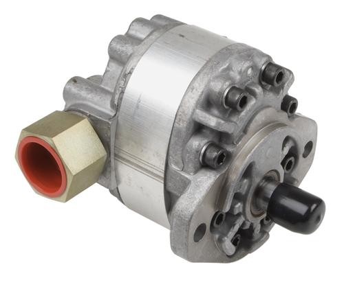
The unit is designed to look like front-mounted tractor weights but actually adds less than 150 lbs. to the front of the tractor. The unit holds a little over 5 gal. of hydraulic oil. A 9 gpm vane pump is embedded inside the reservoir.
Once installed, the tractor has hydraulic power whether or not the clutch is engaged. Most older model tractors have low or limited internal pump flow the hydraulics only work as long as the clutch is engaged.
"The 9gpm pump has enough flow to run most any combination of hydraulic applications, independent of the tractor"s internal hydraulics. A side benefit is having the reservoir on the front of the tractor to give added weight to the front. The unit is as wide as the tractor hood and extends about 8 in. past the grill," says Jackson.
He offers a wide range of hydraulic valves and remotes to match the system, which can be used for log splitters, dump trailers, grain augers, stump grinders, and even add-on power steering.
Inventor Roland Jackson is starting out with Fords (9N, 8N, 2N, NAA, 600 Series, 800 Series and early 1000 Series). However, he will soon be adding other models since the hydraulics are the same. Only the mounting brackets are different.
Add-On "Live Hydraulics" For Older Model Tractors TRACTORS Hydraulics 30-1-32 This new front-mounted hydraulic system, recently introduced by Jackson Power Steering, is designed to give older tractors a "live hydraulics" system that"s reliable, strong and trouble-free. The unit is designed to look like front-mounted tractor weights but actually adds less than 150 lbs. to the front of the tractor. The unit holds a little over 5 gal. of hydraulic oil. A 9 gpm vane pump is embedded inside the reservoir. Once installed, the tractor has hydraulic power whether or not the clutch is engaged. Most older model tractors have low or limited internal pump flow the hydraulics only work as long as the clutch is engaged. "The 9gpm pump has enough flow to run most any combination of hydraulic applications, independent of the tractor"s internal hydraulics. A side benefit is having the reservoir on the front of the tractor to give added weight to the front. The unit is as wide as the tractor hood and extends about 8 in. past the grill," says Jackson.He offers a wide range of hydraulic valves and remotes to match the system, which can be used for log splitters, dump trailers, grain augers, stump grinders, and even add-on power steering.Inventor Roland Jackson is starting out with Fords (9N, 8N, 2N, NAA, 600 Series, 800 Series and early 1000 Series). However, he will soon be adding other models since the hydraulics are the same. Only the mounting brackets are different.The kit includes the reservoir, embedded pump, mounting brackets, crankshaft drive kit, and instructions. Sells for $1,495 plus shipping.Contact: FARM SHOW Followup, Jackson Power Steering, Rt. 2, Box 220, Jetmore, Kan. 67854 (ph 620 357-6546; sales@jacksonpowersteering.com).

Centrifugal pump design provides good resistance to abrasive solutions and extra flow for agitation. The advantages of the hydraulic pump are mounting versatility, customized performance, and ease of maintenance. They are designed to offer long trouble-free life when matched to a hydraulic power source which will give the correct oil flow and pressure. A wide range of pump outputs can be achieved by simply controlling oil flow and pressure to the hydraulic motor.
We offer a comprehensive range of rugged and dependable products to meet virtually any flow, pressure, material and cost requirement. Tough open and closed center tractor applications challenge any pump’s reliability. Delavan Magnum pumps meet the challenge with superior design, precision engineering and high-quality components.
These hydraulically-driven, cast iron and stainless steel pumps provide fluid flow up to 191 GPM and pressure to 140 PSI, at temperatures up to 140°F. They are available in open and closed hydraulic system configurations.
Additional features include a corrosion-resistant nylon impeller and Viton/ceramic seals, as standard. A polypropylene impeller and Viton/silicon carbide seals are available. A standard selection of hydraulic motors offers simple off-the-shelf replacement and covers all applications, and types of tractors. Optimum hydraulic performance is achieved with an optimally matched pump and motor, which provides cooler running temperatures for less heat and longer life.
Check that the pump shaft is rotating. Even though coupling guards and C-face mounts can make this difficult to confirm, it is important to establish if your pump shaft is rotating. If it isn’t, this could be an indication of a more severe issue, and this should be investigated immediately.
Check the oil level. This one tends to be the more obvious check, as it is often one of the only factors inspected before the pump is changed. The oil level should be three inches above the pump suction. Otherwise, a vortex can form in the reservoir, allowing air into the pump.
What does the pump sound like when it is operating normally? Vane pumps generally are quieter than piston and gear pumps. If the pump has a high-pitched whining sound, it most likely is cavitating. If it has a knocking sound, like marbles rattling around, then aeration is the likely cause.
Cavitation is the formation and collapse of air cavities in the liquid. When the pump cannot get the total volume of oil it needs, cavitation occurs. Hydraulic oil contains approximately nine percent dissolved air. When the pump does not receive adequate oil volume at its suction port, high vacuum pressure occurs.
This dissolved air is pulled out of the oil on the suction side and then collapses or implodes on the pressure side. The implosions produce a very steady, high-pitched sound. As the air bubbles collapse, the inside of the pump is damaged.
While cavitation is a devastating development, with proper preventative maintenance practices and a quality monitoring system, early detection and deterrence remain attainable goals. UE System’s UltraTrak 850S CD pump cavitation sensor is a Smart Analog Sensor designed and optimized to detect cavitation on pumps earlier by measuring the ultrasound produced as cavitation starts to develop early-onset bubbles in the pump. By continuously monitoring the impact caused by cavitation, the system provides a simple, single value to trend and alert when cavitation is occurring.
The oil viscosity is too high. Low oil temperature increases the oil viscosity, making it harder for the oil to reach the pump. Most hydraulic systems should not be started with the oil any colder than 40°F and should not be put under load until the oil is at least 70°F.
Many reservoirs do not have heaters, particularly in the South. Even when heaters are available, they are often disconnected. While the damage may not be immediate, if a pump is continually started up when the oil is too cold, the pump will fail prematurely.
The suction filter or strainer is contaminated. A strainer is typically 74 or 149 microns in size and is used to keep “large” particles out of the pump. The strainer may be located inside or outside the reservoir. Strainers located inside the reservoir are out of sight and out of mind. Many times, maintenance personnel are not even aware that there is a strainer in the reservoir.
The suction strainer should be removed from the line or reservoir and cleaned a minimum of once a year. Years ago, a plant sought out help to troubleshoot a system that had already had five pumps changed within a single week. Upon closer inspection, it was discovered that the breather cap was missing, allowing dirty air to flow directly into the reservoir.
A check of the hydraulic schematic showed a strainer in the suction line inside the tank. When the strainer was removed, a shop rag was found wrapped around the screen mesh. Apparently, someone had used the rag to plug the breather cap opening, and it had then fallen into the tank. Contamination can come from a variety of different sources, so it pays to be vigilant and responsible with our practices and reliability measures.
The electric motor is driving the hydraulic pump at a speed that is higher than the pump’s rating. All pumps have a recommended maximum drive speed. If the speed is too high, a higher volume of oil will be needed at the suction port.
Due to the size of the suction port, adequate oil cannot fill the suction cavity in the pump, resulting in cavitation. Although this rarely happens, some pumps are rated at a maximum drive speed of 1,200 revolutions per minute (RPM), while others have a maximum speed of 3,600 RPM. The drive speed should be checked any time a pump is replaced with a different brand or model.
Every one of these devastating causes of cavitation threatens to cause major, irreversible damage to your equipment. Therefore, it’s not only critical to have proper, proactive practices in place, but also a monitoring system that can continuously protect your valuable assets, such as UE System’s UltraTrak 850S CD pump cavitation senor. These sensors regularly monitor the health of your pumps and alert you immediately if cavitation symptoms are present, allowing you to take corrective action before it’s too late.
Aeration is sometimes known as pseudo cavitation because air is entering the pump suction cavity. However, the causes of aeration are entirely different than that of cavitation. While cavitation pulls air out of the oil, aeration is the result of outside air entering the pump’s suction line.
Several factors can cause aeration, including an air leak in the suction line. This could be in the form of a loose connection, a cracked line, or an improper fitting seal. One method of finding the leak is to squirt oil around the suction line fittings. The fluid will be momentarily drawn into the suction line, and the knocking sound inside the pump will stop for a short period of time once the airflow path is found.
A bad shaft seal can also cause aeration if the system is supplied by one or more fixed displacement pumps. Oil that bypasses inside a fixed displacement pump is ported back to the suction port. If the shaft seal is worn or damaged, air can flow through the seal and into the pump’s suction cavity.
As mentioned previously, if the oil level is too low, oil can enter the suction line and flow into the pump. Therefore, always check the oil level with all cylinders in the retracted position.
If a new pump is installed and pressure will not build, the shaft may be rotating in the wrong direction. Some gear pumps can be rotated in either direction, but most have an arrow on the housing indicating the direction of rotation, as depicted in Figure 2.
Pump rotation should always be viewed from the shaft end. If the pump is rotated in the wrong direction, adequate fluid will not fill the suction port due to the pump’s internal design.
A fixed displacement pump delivers a constant volume of oil for a given shaft speed. A relief valve must be included downstream of the pump to limit the maximum pressure in the system.
After the visual and sound checks are made, the next step is to determine whether you have a volume or pressure problem. If the pressure will not build to the desired level, isolate the pump and relief valve from the system. This can be done by closing a valve, plugging the line downstream, or blocking the relief valve. If the pressure builds when this is done, there is a component downstream of the isolation point that is bypassing. If the pressure does not build up, the pump or relief valve is bad.
If the system is operating at a slower speed, a volume problem exists. Pumps wear over time, which results in less oil being delivered. While a flow meter can be installed in the pump’s outlet line, this is not always practical, as the proper fittings and adapters may not be available. To determine if the pump is badly worn and bypassing, first check the current to the electric motor. If possible, this test should be made when the pump is new to establish a reference. Electric motor horsepower is relative to the hydraulic horsepower required by the system.
For example, if a 50-GPM pump is used and the maximum pressure is 1,500 psi, a 50-hp motor will be required. If the pump is delivering less oil than when it was new, the current to drive the pump will drop. A 230-volt, 50-hp motor has an average full load rating of 130 amps. If the amperage is considerably lower, the pump is most likely bypassing and should be changed.
Figure 4.To isolate a fixed displacement pump and relief valve from the system, close a valve or plug the line downstream (left). If pressure builds, a component downstream of the isolation point is bypassing (right).
The most common type of variable displacement pump is the pressure-compensating design. The compensator setting limits the maximum pressure at the pump’s outlet port. The pump should be isolated as described for the fixed displacement pump.
If pressure does not build up, the relief valve or pump compensator may be bad. Prior to checking either component, perform the necessary lockout procedures and verify that the pressure at the outlet port is zero psi. The relief valve and compensator can then be taken apart and checked for contamination, wear, and broken springs.
Install a flow meter in the case drain line and check the flow rate. Most variable displacement pumps bypass one to three percent of the maximum pump volume through the case drain line. If the flow rate reaches 10 percent, the pump should be changed. Permanently installing a flow meter in the case drain line is an excellent reliability and troubleshooting tool.
Ensure the compensator is 200 psi above the maximum load pressure. If set too low, the compensator spool will shift and start reducing the pump volume when the system is calling for maximum volume.
Performing these recommended tests should help you make good decisions about the condition of your pumps or the cause of pump failures. If you change a pump, have a reason for changing it. Don’t just do it because you have a spare one in stock.
Conduct a reliability assessment on each of your hydraulic systems so when an issue occurs, you will have current pressure and temperature readings to consult.
Al Smiley is the president of GPM Hydraulic Consulting Inc., located in Monroe, Georgia. Since 1994, GPM has provided hydraulic training, consulting and reliability assessments to companies in t...

A hydraulic lift is a device for moving objects using force created by pressure on a liquid inside a cylinder that moves a piston upward. Incompressible oil is pumped into the cylinder, which forces the piston upward. When a valve opens to release the oil, the piston lowers by gravitational force.
The principle for hydraulic lifts is based on Pascal‘s law for generating force or motion, which states that pressure change on an incompressible liquid in a confined space is passed equally throughout the liquid in all directions.
The concept of Pascal‘s law and its application to hydraulics can be seen in the example below, where a small amount of force is applied to an incompressible liquid on the left to create a large amount of force on the right.
A hydraulic system works by applying force at one point to an incompressible liquid, which sends force to a second point. The process involves two pistons that are connected by an oil filled pipe.
The diagram below represents a simple version of the working mechanism of a hydraulic device. The handle on the right moves the incompressible oil, under pressure, from the reservoir to the high pressure chamber in the middle of the diagram. The ram moves up as the oil is pumped in.
The force generated in a hydraulic system depends on the size of the pistons. If the smaller of the two pistons is two inches and the larger piston is six inches, or three times as large, the amount of force created will be nine times greater than the amount of force from the smaller piston. One hundred pounds of force by a small piston will be able to lift 900 pounds.
The purposes of hydraulic systems widely vary, but the principles of how hydraulic systems work and their components remain the same for all applications. The most significant part of a hydraulic system is the fluid or liquid. The laws of physics dictate that the pressure on the fluid will remain unchanged as it is transmitted across a hydraulic system. Below is an explanation of each part of a hydraulic system.
Hydraulic Circuits control the flow and pressure of the liquid in the system. The image below shows all of the different parts of a hydraulic circuit.
Hydraulic Pump converts mechanical power into hydraulic energy. Hydraulic pumps create a vacuum at the pump inlet, which forces liquid from the reservoir into the inlet line and out to the outlet to the hydraulic system.
Hydraulic Motor is an actuator to convert hydraulic pressure into torque and rotation. It takes the pressure and flow of the hydraulic energy and changes it into rotational mechanical energy, similar to a linear actuator. The pump sends hydraulic energy into the system, where it pushes the hydraulic motor.
Hydraulic Cylinder converts the energy in the hydraulic fluid into force and initiates the pressure in the fluid that is controlled by the hydraulic motor.
Hydraulic Fluids transfer power in a hydraulic system. Most hydraulic fluids are mineral oil or water. The first hydraulic fluid was water before mineral oil was introduced in the twentieth century. Glycol ether, organophosphate ester, polyalphaolefin, propylene glycol, and silicone oil are used for high temperature applications and fire resistance.
Hydraulic lifts, in their many forms, have become an essential part of several industries from helping patients in and out of bed to specially designed lifts to help people board a bus. The number of uses of hydraulic lifts has been growing rapidly in recent years.
Medical lifts are lifting devices for surgical tables, hospital beds, and monitoring equipment. Hospital beds are a convenient means for moving patients from their rooms to treatment areas. Hydraulics control the height of all parts of the bed to make it more acceptable for hospital staff.
Post car lifts are a variation of automotive lifts. The vehicle to be repaired is suspended between two posts with hydraulic drives that have four arms. They are designed to lift any type of vehicle.
Hand pumped lifts are raised by a manual hydraulic hand pump and have a release lever to lower the load. They are very sturdy and maintenance free with the ability to lift one ton over six feet.
The main components of a VRC are a guide column, carriage, and hydraulic actuating mechanism. VRCs can be mechanical or hydraulic with the hydraulic version capable of lifting loads weighing between 3,000 pounds and 6,000 pounds. Hydraulic VRCs are less costly to install than mechanical ones and perfect for lifting applications that are limited to two levels under 25 feet and do not require continuous cycle use.
Rotating hydraulic lift tables are a special type of lift table that have a rotating turntable that is recessed into the surface of the table for positioning a load, which makes the table accessible on four sides. The turntable rests on anti friction bearings such that it can turn easily and effortlessly. When it is not needed, it can be locked in position. Rotating hydraulic lift tables can be low profile hydraulic tables that can be lowered to a few inches off the floor for easy access by a pallet jack or forklift.
As with all hydraulic tables, rotating hydraulic tables are made of highly durable materials capable of lifting close to a ton of products and items. They are designed to perfectly and precisely position a load to prevent workers from having to manually lift materials.
Low profile lift tables have a collapsed height of a few inches allowing the table to be loaded using a hand truck or forklift. Since they do not require a pit or indent in the floor, they can be used on upper floors as well as the main floor. To activate the hydraulic lift of the table, there is a foot switch or push button remote.an operator can use that raises or lowers the table to a comfortable working height.
High capacity hydraulic lift tables are heavy duty tools designed to lift loads up to 60 tons with lifting heights of 52 inches up to 92 inches and platforms from 4’ by 6’ up to 10’ by 22’ with customized larger platforms available. They have scissor legs and torque tubes that add stability and exceptional support and prevent load deflection or shift.
The number of scissor legs and hydraulic cylinders vary according to the design of the table and the manufacturer. As with other hydraulic tables, high capacity tables can be activated by a handheld pendant or foot switch with an upper travel limit switch. Possible additional features include tilt tops, powered turntables, V cradles, and corrosion resistant finishes to name a few.
High capacity hydraulic lift tables are the workhorses of lift tables and are designed to withstand the stress and constant use of heavy duty machinery.
Hydraulic lifts are constructed from steel and have precision accuracy. Their sturdy and durable design has made them popular in a wide variety of industries. Listed below are a few of the industries that rely on hydraulic lifts for their efficiency and ability to supply a great amount of force.
Electro-hydraulics is a common use of hydraulics in industrial applications. The main advantages of hydraulics are its rapid response times and precision. Plastic processing, metal extraction applications, automated production, machine tool industry, paper industries, loaders, crushers, presses, and the textile industry are some of the industrial uses of hydraulics. The image below is a hydraulic press from the plastics industry.
Mobile hydraulics have the advantage of being able to be moved to different conditions and situations. They are especially useful in the construction and building industries where hydraulics are used as cranes, excavators, backhoes, and earth moving equipment. Pictured below is a concrete boom truck using a hydraulic arm to unload concrete.
The automotive industry is the largest user of hydraulics. Production, repair, and internal components on cars all use hydraulics.The image below shows the use of hydraulic automation in the production of trucks.
Marine hydraulics deliver linear and rotary force and torque rapidly and efficiently. The three types of marine hydraulic systems are open, closed, and semi-closed. They are used for cranes, mooring and anchor winches, stabilizers, steering, thrusters, propellers, and platforms.
Components for aircraft have to meet strict standards before being approved for use. Hydraulic pumps and valves meet aircraft regulations and are an essential part of aircraft design and production. Wing adjustments, retraction and extension of landing gear, opening/closing of doors, brakes, and steering are all performed by hydraulics. The image below provides a list of some of the ways hydraulics are used on an aircraft.
Hydraulics are ideal for mining for the same reasons that they are used for other manufacturing operations. Power, controllability, reliability, and serviceability are necessities in mining because of the dangers that are involved. Unlike other manufacturing, mining works on a huge scale requiring massive equipment. The power and force provided by hydraulics fits the conditions.
Hydraulics lifts are heavy duty equipment that can supply a great deal of force. The Occupational Safety and Health Administration (OSHA) and the American National Standards Institute (ANSI) have specific requirements regarding the operation of hydraulic lifts. The first of those requirements is that operators must be an adult, over 18, that have been fully trained in the operation and dangers of the equipment.
The principle for hydraulic lifts is based on Pascal‘s law for generating force or motion, which states that pressure change on an incompressible liquid in a confined space is passed equally throughout the liquid in all directions.
The Occupational Safety and Health Administration (OSHA) and the American National Standards Institute (ANSI) have specific requirements regarding the operation of hydraulic lifts and training for operators.

Hydraulic Monoblock Valves are a style of Hydraulic Control valve. These valves are used to start and stop fluid flow into hydraulic cylinders or hydraulic motors. The number of cylinders or motors that a control valve can operate depends on the number of spools on the valve. The flow rates listed is the maximum allowed GPM (Gallons Per Minute) that can be put through a valve. A common example of a hydraulic control valve is the loader valve on a tractor. These valves have power beyond Capability (Power Beyond Adapter Sleeve is required SKU: P40G-PB), as well as the ability to operate as a closed-center valve (Closed-Center Plug Required SKU: P40G-CC).
Is the flow through this valve less than 13 GPM? If not, then we have largerZ80 valves that can accommodate up to 21 GPM, and Z100 Valves if the flow is between 21 GPM and 27 GPM. If installing on a tractor please check tractor-data.com, it will say under the hydraulics – “Pump Flow” – of the data sheet. The GPM flow may be printed on the pump itself.
Do you have an open-center hydraulic system? If you’re installing this on a tractor please check tractor-data.com, it will say under the hydraulics of the data sheet. These valves are setup for use on open-center hydraulic systems. If you do have a closed-center system you’ll need to get the closed center adapter plug. NOTE: None of our valves have load-sensing capabilities.
Do you have other valves downstream from this valve (Examples include: Other Control Valves, Rear Remote Valve, Backhoe Valve, 3-Point Valve)? If so, you’ll need the power beyond adapter sleeve to provide pressure and flow to those valves. Note: This is only needed on open-center hydraulic systems. If you have a closed-center system, you will tee into a pressure line to connect other valves.
Are you operating a hydraulic cylinder or a hydraulic motor?If you’re operating a hydraulic cylinder you’ll need to get “A” spools for double acting cylinders, if you’re operating a hydraulic motor you’ll need “D” spools for motor control. Note: “D” spools cannot be used for operating hydraulic cylinders and “A” spools cannot be used to operate hydraulic motors.
Do you need a switch or do you want to provide your own?This valve can be purchased with a spring-to-center rocker switch. These are momentary push-button switches that allow you to extend/retract cylinder or turn on/off hydraulic motors. As soon as the button is released fluid the flow into the cylinder or motor will stop. These switches with this valve include the 10′ Harness, giving you 12′ between switch and valve. If you’d rather build or provide your own switch that can be done as well. You will connect your power and ground to the two parallel posts (Do not use third post).

(b) Maximum flow capacity is 15.5 GPM on some models equipped with larger hydraulic pump. On these models, the motor recommended is the HM5C for both the
(a) Series 10 tractors with closed center systems have the valves located at the rear of the tractor. Open center series 10 tractors have the valves located under the
(b) This type of closed center system uses a constant displacement pump. Contact Ford New Holland before operating a hydraulic-driven pump on this system.
(a) For tractors built prior to November 1980, International Harvester Service Bulletin S-3436 (dated March 1977) advises that continuous hydraulic demand on the
(a) remote outlet valves such as that created by hydraulic motors, can cause damage to the tractor hydraulic system. In gear-driven tractors (86 series, 2 wheel drive),
(a) the MCV pump charge circuit would not be receiving its normal flow, and in Hydrostatic-drive tractors, the oil cooler circuit would not be receiving its normal flow.


 8613371530291