
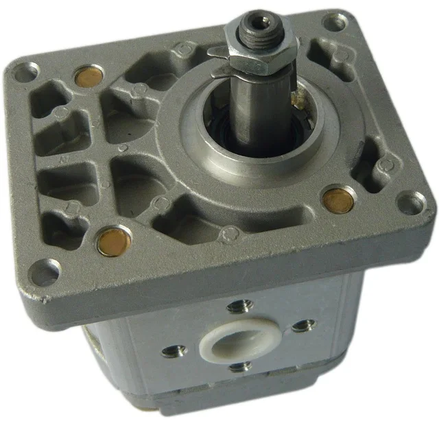
tractor hydraulic pump pressure free sample
Things like restrictions and blockages can impede the flow of fluid to your pump. which could contribute to poor fluid flow. Air leak in suction line. Air present in the pump at startup. Insufficient supply of oil in pump. Clogged or dirty fluid filters. Clogged inlet lines or hoses. Blocked reservoir breather vent. Low oil in the reservoir
Now that we’ve ensured that the directional control is not reversed, it’s time to check that the drive motor itself is turning in the right direction. Sometimes incorrect installation leads to mismatched pipe routings between control valves and motors, which can reverse the direction of flow. Check to see that the motor is turning the pump in the right direction and if not - look at your piping.
Check to ensure that your pump drive motor is turning over and is developing the required speed and torque. In some cases, misalignment can cause binding of the drive shaft, which can prevent the motor from turning. If this is the case, correct the misalignment and inspect the motor for damage. If required, overhaul or replace motor.
Check to ensure the pump to motor coupling is undamaged. A sheared pump coupling is an obvious cause of failure, however the location of some pumps within hydraulic systems makes this difficult to check so it may go overlooked
It is possible that the entire flow could be passing over the relief valve, preventing the pressure from developing. Check that the relief valve is adjusted properly for the pump specifications and the application.
Seized bearings, or pump shafts and other internal damage may prevent the pump from operating all together. If everything else checks out, uncouple the pump and motor and check to see that the pump shaft is able to turn. If not, overhaul or replace the pump.
If your pump is having problems developing sufficient power, following this checklist will help you to pinpoint the problem. In some cases you may find a simple solution is the answer. If your pump is exhibiting any other issues such as noise problems, heat problems or flow problems, you may need to do some more investigation to address the root cause of your pump problem. To help, we’ve created a downloadable troubleshooting guide containing more information about each of these issues. So that you can keep your system up and running and avoid unplanned downtime. Download it here.

Over the years, revolutionary advancements have been instigated in the tractor control systems’ field. These changes are primarily attributed to integrating various hydraulic inventions in the tipping trailer, braking system, implementing control structure, and steering to enhance this machinery’s optimum functionality. Hydraulic flow and pressure can be translated to motion and forces that enhance a tractor’s capacity to execute tasks that operators cannot perform manually or physically (Gannon, 2017). This paper provides a comprehensive discussion of tractor hydraulics and highlights the benefits of this particular technology.
There are two forms of hydraulic systems: the open- and closed-center structures. The latter is typical in modern-day farm equipment; this includes most tractor models. When in neutral, this system’s closed center valve obstructs oil flow from the pump. This fluid travels to an accumulator, which typically stores it under pressure. The valves also block fluid flow via the center when the hydraulic is in the aforementioned state. A variable flow pump also halts its operation following the closure of the valve. Open hydraulic structures were commonly used in most of the preliminary tractors. When in neutral, this system’s open-center valves link all lines back to the reservoir, directly bypassing the pump, which is always in operation, fostering the constant flow of oil without accumulating pressure. Valves also allow the flow of fluid through the center and into the reservoir during this particular.
Hydraulic oil, particularly non-pressurized fluid, is usually stored in the reservoir. According to Moinfar and Shahgholi (2018), reservoirs are usually vented towards the atmosphere to acclimatize the changing levels of oil. The air vent is fitted with filters to impede the entry of dust or dirt into the reservoir. The reservoir’s metallic walls enhance the cooling process of the fluid by improving the outflow of heat. The decreased pressure within this structure also gives room for dissolved or trapped air to escape from the hydraulic fluid. A sufficient surface area is also essential to foster the dispersal of heat.
JIC and NPTF fittings prevent hydraulic components’ port leakage. NPTF taper pipe threads hinder seepage by using the male-to-female resistance thread taper. On the other hand, JICs sue O-ring (Moinfar & Shahgholi, 2018). The brake hydraulic system’s components are usually joined using hoses and lines. The latter connects the hydraulic system’s stationary parts while hoses consolidate in motion. The hose, tubing, or pipe’s size is crucial (Moinfar & Shahgholi, 2018). If the hose’s size is minimal, the flow of oil increases rapidly, generating heat and causing the fluid to lose power. The cost and time for installing a large hose, on the other hand, can be too high.
The hydraulic pump plays a crucial role in enhancing fluid transmission from the reservoir and towards the hydraulic system. This process elevates the fluid’s energy level by triggering significant surges in its pressure. A one-phase pump typically has a single flow rate and one maximal pressure. These pumps are usually attached to the PTO shaft or crankshaft on a farm tractor. These pumps are often fitted on manual loaders and backhoes. On the other hand, a two-step pump first generates high fluid volumes by enhancing the cylinder’s rapid in-and-out movements. In case of any form of resistance, an additional gear set is used to create high pressure for splitting and lifting. Nonetheless, the fluid’s volume will reduce significantly during this phase.
Examples of valves fitted in the hydraulic system of a tractor include the flow, pressure, and direction control valve. They function by stopping or impeding liquid or pressure flow and controlling the quantity, pressure, and direction of flow. The motor is located within the pump’s power source, i.e., the cylinder. The fluid with high-pressure levels exerts its action on the piston and rod located within the hydraulic cylinder (Gosaye et al., 2015). Each cylinder stroke converts or translates the power or pressure of the fluid into mechanical force or work. While the piston and rod extend, the reservoir’s oil levels decrease, and when these two devices retract, the fluid flows back to the reservoir.
The pressure is typically applied or exerted on one region of the piston in single-acting cylinders; thus, mechanical force occurs in a single direction only. The cylinder then assumes its initial position under the load’s weight. Contrarily, pressure may be exerted on both sides of the piston in double-acting cylinders. Consequently, work takes place in either direction. The fixed ends in welded cylinders are usually welded to increase the durability and strength for high-pressure functions. Four rods are typically used to hold tie-rod cylinders together.
The instigation of hydraulics triggered significant changes in the agricultural industry, especially concerning the manner and method of production. The adoption of this technology has triggered substantial reductions in the level of manual power or effort needed to perform farm-related activities both in terms of work animals and workers (“How Hydraulics Transformed,” 2019). The tractor has also been effective in decreasing the risks associated with farm-related injuries by minimizing the number of hours individuals spend working in agricultural fields. This invention has also helped restrict the downtime rate amid agricultural operations. Furthermore, it has been crucial in promoting personal and overall productivity and efficiency during practice.
Significant advancements in agricultural engineering, particularly in tractor hydraulics, have triggered farm-related practices’ efficacy and efficiency. The tractor hydraulic system has several components, including the reservoir, pump, and motor. Hydraulics foster a tractor operator’s capacity to execute tasks that demand substantial effort with an electrical switch flip or simple lever push, which, in turn, actuates the hydraulic circuit. Contemporary farming integrates the use of hydraulics for operations that were initially controlled by mechanical means.
Gosaye, C., Mengiste, Z., & Hailu, A. (2015). Evaluation of the compatibility of tractors and implements at Tendaho Sugar Estate. ARPN Journal of Science and Technology, 5(10), 476–483. Web.

Centrifugal pump design provides good resistance to abrasive solutions and extra flow for agitation. The advantages of the hydraulic pump are mounting versatility, customized performance, and ease of maintenance. They are designed to offer long trouble-free life when matched to a hydraulic power source which will give the correct oil flow and pressure. A wide range of pump outputs can be achieved by simply controlling oil flow and pressure to the hydraulic motor.
We offer a comprehensive range of rugged and dependable products to meet virtually any flow, pressure, material and cost requirement. Tough open and closed center tractor applications challenge any pump’s reliability. Delavan Magnum pumps meet the challenge with superior design, precision engineering and high-quality components.
These hydraulically-driven, cast iron and stainless steel pumps provide fluid flow up to 191 GPM and pressure to 140 PSI, at temperatures up to 140°F. They are available in open and closed hydraulic system configurations.
Additional features include a corrosion-resistant nylon impeller and Viton/ceramic seals, as standard. A polypropylene impeller and Viton/silicon carbide seals are available. A standard selection of hydraulic motors offers simple off-the-shelf replacement and covers all applications, and types of tractors. Optimum hydraulic performance is achieved with an optimally matched pump and motor, which provides cooler running temperatures for less heat and longer life.

Check that the pump shaft is rotating. Even though coupling guards and C-face mounts can make this difficult to confirm, it is important to establish if your pump shaft is rotating. If it isn’t, this could be an indication of a more severe issue, and this should be investigated immediately.
Check the oil level. This one tends to be the more obvious check, as it is often one of the only factors inspected before the pump is changed. The oil level should be three inches above the pump suction. Otherwise, a vortex can form in the reservoir, allowing air into the pump.
What does the pump sound like when it is operating normally? Vane pumps generally are quieter than piston and gear pumps. If the pump has a high-pitched whining sound, it most likely is cavitating. If it has a knocking sound, like marbles rattling around, then aeration is the likely cause.
Cavitation is the formation and collapse of air cavities in the liquid. When the pump cannot get the total volume of oil it needs, cavitation occurs. Hydraulic oil contains approximately nine percent dissolved air. When the pump does not receive adequate oil volume at its suction port, high vacuum pressure occurs.
This dissolved air is pulled out of the oil on the suction side and then collapses or implodes on the pressure side. The implosions produce a very steady, high-pitched sound. As the air bubbles collapse, the inside of the pump is damaged.
While cavitation is a devastating development, with proper preventative maintenance practices and a quality monitoring system, early detection and deterrence remain attainable goals. UE System’s UltraTrak 850S CD pump cavitation sensor is a Smart Analog Sensor designed and optimized to detect cavitation on pumps earlier by measuring the ultrasound produced as cavitation starts to develop early-onset bubbles in the pump. By continuously monitoring the impact caused by cavitation, the system provides a simple, single value to trend and alert when cavitation is occurring.
The oil viscosity is too high. Low oil temperature increases the oil viscosity, making it harder for the oil to reach the pump. Most hydraulic systems should not be started with the oil any colder than 40°F and should not be put under load until the oil is at least 70°F.
Many reservoirs do not have heaters, particularly in the South. Even when heaters are available, they are often disconnected. While the damage may not be immediate, if a pump is continually started up when the oil is too cold, the pump will fail prematurely.
The suction filter or strainer is contaminated. A strainer is typically 74 or 149 microns in size and is used to keep “large” particles out of the pump. The strainer may be located inside or outside the reservoir. Strainers located inside the reservoir are out of sight and out of mind. Many times, maintenance personnel are not even aware that there is a strainer in the reservoir.
The suction strainer should be removed from the line or reservoir and cleaned a minimum of once a year. Years ago, a plant sought out help to troubleshoot a system that had already had five pumps changed within a single week. Upon closer inspection, it was discovered that the breather cap was missing, allowing dirty air to flow directly into the reservoir.
A check of the hydraulic schematic showed a strainer in the suction line inside the tank. When the strainer was removed, a shop rag was found wrapped around the screen mesh. Apparently, someone had used the rag to plug the breather cap opening, and it had then fallen into the tank. Contamination can come from a variety of different sources, so it pays to be vigilant and responsible with our practices and reliability measures.
The electric motor is driving the hydraulic pump at a speed that is higher than the pump’s rating. All pumps have a recommended maximum drive speed. If the speed is too high, a higher volume of oil will be needed at the suction port.
Due to the size of the suction port, adequate oil cannot fill the suction cavity in the pump, resulting in cavitation. Although this rarely happens, some pumps are rated at a maximum drive speed of 1,200 revolutions per minute (RPM), while others have a maximum speed of 3,600 RPM. The drive speed should be checked any time a pump is replaced with a different brand or model.
Every one of these devastating causes of cavitation threatens to cause major, irreversible damage to your equipment. Therefore, it’s not only critical to have proper, proactive practices in place, but also a monitoring system that can continuously protect your valuable assets, such as UE System’s UltraTrak 850S CD pump cavitation senor. These sensors regularly monitor the health of your pumps and alert you immediately if cavitation symptoms are present, allowing you to take corrective action before it’s too late.
Aeration is sometimes known as pseudo cavitation because air is entering the pump suction cavity. However, the causes of aeration are entirely different than that of cavitation. While cavitation pulls air out of the oil, aeration is the result of outside air entering the pump’s suction line.
Several factors can cause aeration, including an air leak in the suction line. This could be in the form of a loose connection, a cracked line, or an improper fitting seal. One method of finding the leak is to squirt oil around the suction line fittings. The fluid will be momentarily drawn into the suction line, and the knocking sound inside the pump will stop for a short period of time once the airflow path is found.
A bad shaft seal can also cause aeration if the system is supplied by one or more fixed displacement pumps. Oil that bypasses inside a fixed displacement pump is ported back to the suction port. If the shaft seal is worn or damaged, air can flow through the seal and into the pump’s suction cavity.
As mentioned previously, if the oil level is too low, oil can enter the suction line and flow into the pump. Therefore, always check the oil level with all cylinders in the retracted position.
If a new pump is installed and pressure will not build, the shaft may be rotating in the wrong direction. Some gear pumps can be rotated in either direction, but most have an arrow on the housing indicating the direction of rotation, as depicted in Figure 2.
Pump rotation should always be viewed from the shaft end. If the pump is rotated in the wrong direction, adequate fluid will not fill the suction port due to the pump’s internal design.
A fixed displacement pump delivers a constant volume of oil for a given shaft speed. A relief valve must be included downstream of the pump to limit the maximum pressure in the system.
After the visual and sound checks are made, the next step is to determine whether you have a volume or pressure problem. If the pressure will not build to the desired level, isolate the pump and relief valve from the system. This can be done by closing a valve, plugging the line downstream, or blocking the relief valve. If the pressure builds when this is done, there is a component downstream of the isolation point that is bypassing. If the pressure does not build up, the pump or relief valve is bad.
If the system is operating at a slower speed, a volume problem exists. Pumps wear over time, which results in less oil being delivered. While a flow meter can be installed in the pump’s outlet line, this is not always practical, as the proper fittings and adapters may not be available. To determine if the pump is badly worn and bypassing, first check the current to the electric motor. If possible, this test should be made when the pump is new to establish a reference. Electric motor horsepower is relative to the hydraulic horsepower required by the system.
For example, if a 50-GPM pump is used and the maximum pressure is 1,500 psi, a 50-hp motor will be required. If the pump is delivering less oil than when it was new, the current to drive the pump will drop. A 230-volt, 50-hp motor has an average full load rating of 130 amps. If the amperage is considerably lower, the pump is most likely bypassing and should be changed.
Figure 4.To isolate a fixed displacement pump and relief valve from the system, close a valve or plug the line downstream (left). If pressure builds, a component downstream of the isolation point is bypassing (right).
The most common type of variable displacement pump is the pressure-compensating design. The compensator setting limits the maximum pressure at the pump’s outlet port. The pump should be isolated as described for the fixed displacement pump.
If pressure does not build up, the relief valve or pump compensator may be bad. Prior to checking either component, perform the necessary lockout procedures and verify that the pressure at the outlet port is zero psi. The relief valve and compensator can then be taken apart and checked for contamination, wear, and broken springs.
Install a flow meter in the case drain line and check the flow rate. Most variable displacement pumps bypass one to three percent of the maximum pump volume through the case drain line. If the flow rate reaches 10 percent, the pump should be changed. Permanently installing a flow meter in the case drain line is an excellent reliability and troubleshooting tool.
Ensure the compensator is 200 psi above the maximum load pressure. If set too low, the compensator spool will shift and start reducing the pump volume when the system is calling for maximum volume.
Performing these recommended tests should help you make good decisions about the condition of your pumps or the cause of pump failures. If you change a pump, have a reason for changing it. Don’t just do it because you have a spare one in stock.
Conduct a reliability assessment on each of your hydraulic systems so when an issue occurs, you will have current pressure and temperature readings to consult.
Al Smiley is the president of GPM Hydraulic Consulting Inc., located in Monroe, Georgia. Since 1994, GPM has provided hydraulic training, consulting and reliability assessments to companies in t...

When a hydraulic system fails, finding the source of the problem can be a challenge. Though hydraulic systems primarily consist of a sump, motor, pump, valves, actuators and hydraulic fluid, any of these parts could be the source of failure. That"s not to mention the additional potential for failure through human error and faulty maintenance practices. If your system fails, you need to know why it fails, how to find the failure and how to keep it running smoothly in the future, all while keeping personnel safe.
It"s often easy to tell when a hydraulic system fails — symptoms can include high temperatures, low pressure readings and slow or erratic operation are glaring problems. But what are the most common causes of hydraulic systems failures? We can trace most hydraulic issues back to a few common causes, listed below.
Air and water contamination are the leading causes of hydraulic failure, accounting for 80 to 90% of hydraulic failures. Faulty pumps, system breaches or temperature issues often cause both types of contamination.
Air contamination is the entrance of air into a hydraulic system and consists of two types — aeration and cavitation. Both can cause severe damage to the hydraulic system over time by wearing down the pump and surrounding components, contaminating hydraulic fluids and even overheating the system. Although we are not pump manufacturers, we know it is essential to be aware of these types of contamination and how to identify their symptoms.
Cavitation:Hydraulic oil consists of about 9% dissolved air, which the pump can pull out and implode, causing pump problems and damage to the pump and to other components in a hydraulic system over time. You can identify this problem if your hydraulic pump is making a whining noise.
Aeration:Aeration occurs when air enters the pump cavity from an outside source. Usually, loose connections or leaks in the system cause this issue. Aeration also creates a sound when the pump is running, which sounds like knocking.
Water contamination is also a common problem in hydraulic systems, often caused by system leaks or condensation due to temperature changes. Water can degrade hydraulic components over time through oxidation and freeze damage. A milky appearance in hydraulic fluid can help you identify water contamination.
Fluid oxidization: Extreme heat can cause hydraulic fluid to oxidize and thicken. This fluid thickening can cause buildups in the system that restrict flow, but can also further reduce the ability of the system to dissipate heat.
Fluid thickening:Low temperatures increase the viscosity of hydraulic oil, making it harder for the oil to reach the pump. Putting systems under load before the oil reaches 70 degrees or more can damage the system through cavitation.
Fluid levels and quality can affect hydraulic system performance. Low fluid levels and inappropriate filtration can result in air contamination, while fluid contamination can cause temperature problems. Leaks can further exacerbate both issues.
Using the correct type of fluid is also essential, as certain hydraulic oils are compatible with specific applications. There are even oil options that offer higher resistance to temperature-related problems. Some oils even offer anti-wear and anti-foam additives to help prevent against wear and air contamination, respectively.
Human error is the base cause of many hydraulic system problems. Some of the most common errors that may result in your hydraulic pump not building pressure include the following.
Faulty installations: Improper installation of any component in a hydraulic system can result in severe errors. For example, the pump shaft may be rotating in the wrong direction, negatively affecting pressure buildup, or pipes may be incorrectly fitted, resulting in leaks.
Incompatible parts: An inexperienced installer may put mismatched components together, resulting in functional failures. For example, a pump may have a motor that runs beyond its maximum drive speed.
Improper maintenance or usage:Using systems outside their operational capabilities or failing to perform regular maintenance are some of the most common causes of hydraulic system damage, but are easy to rectify through updated maintenance policies and training.
The sources of system failures can be tricky to identify, but some hydraulic troubleshooting steps can help narrow down the options. So how do you troubleshoot a hydraulic system? Here are some of the fundamentals.
Check the pump: Take the pump assembly apart and assess all parts to ensure that they are functional and installed correctly. The most common problem areas include the pump shaft, coupling and filter.
Check the fluids:Check the level, color and viscosity of the hydraulic oil to ensure it meets specifications and has not become contaminated. Low hydraulic fluid symptoms include pressure or power loss. When in doubt, drain and replace the fluids.
Check the seals: Look for evidence of any fluid leakage around your hydraulic system"s seals, especially the shaft seal. Leakage can indicate worn-out or blown seals that can cause malfunctions with pumps, motors and control valves.
Check the filters: Ensure filters are clear of plugs and blockages. Common clogged hydraulic filter symptoms include sluggish operation and noisy operation.
Run the system: When you have completed all these essential checks, turn on the system and monitor it for pressure and temperature fluctuations, as well as abnormal sounds. If all seems well, check your pressure sensor for potential failure.
Hydraulic system issues are inevitable at some point. However, simple steps can help you avoid these issues and increase the longevity of your hydraulic system. On top of effective troubleshooting, you can prevent hydraulic system failure by taking the following steps.
Follow specifications: We can trace the most common hydraulic system issues back to fundamental system problems like incompatible or improperly installed parts. For this reason, it"s essential to always double-check specifications to ensure your purchased parts can work together seamlessly.
On top of these steps, look into hydraulic system products that are specifically designed to help prevent failures. One such product is Bear-Loc® by York Precision. This innovative locking actuator is a safe, reliable feature for hydraulic components, automatically locking when sleeve pressure is relieved, preventing movement if a hydraulic system fails. This way, your can protect your personnel from injuries related to hydraulic failures. Even better, York Precision offers in-house design, engineering expertise and machining and manufacturing capabilities to produce a hydraulic locking device that meets your exact specifications.
Regularly review hydraulic system maintenance, always following manufacturer recommendations and industry best practices. Also, consider the storage condition, external influences, working pressure and usage frequency of your system to tailor your maintenance schedule and procedures.
Daily tasks:Take care of a few simple daily checks to avoid issues. For example, personnel should check the oil levels, hoses and connections and listen to the pump for abnormal sounds.
Be mindful of location:Do not stand at endpoints while working on hydraulic systems. This safety measure can help prevent loss of limb and life, as there is a lot of pressure built up in these areas that can release and result in life-threatening situations.
Use caution around running systems:Always keep an eye out on pressure taps, couplings and hoses when they are under pressure. If something does not look right, power down the system before checking it. Loose or faulty parts can easily become deadly projectiles.
The best safety measures, however, are to perform excellent maintenance and use high-quality parts. If you"re looking for a quality hydraulic component manufacturer, York Precision Machining & Hydraulics can help.

One of the more challenging aspects of developing pasture and grazing land is providing access to a reliable water supply for livestock. In some cases, existing streams, creeks, or ponds provide drinking water for the livestock. When a surface water source is not available, wells can be drilled and pumps installed to provide water for the animals. In some instances, surface water may be available, but not accessible to the livestock due to water quality issues, steep access slopes, or fencing issues.
Providing an electrical power source to such a location for a pump can be cost-prohibitive. Utilizing a pump powered by an internal combustion engine can require inspection and attention several times each day and regular fuel supply runs. Nose pumps and sling pumps may be used effectively in some of these situations, but these pumps will not work if the elevation difference between the water source and grazing area is greater than twenty feet. Solar-powered pumps are an excellent option but can be expensive depending on the flow rate and pressure needs of the system.
Figure 1. A 3/4-inch homemade hydraulic ram pump made with PVC fittings. Water flows from right to left during operation. Image credit: W. Bryan Smith, Clemson University.
One possible solution to providing livestock drinking water in remote locations is the hydraulic ram pump. The first development work of the hydraulic ram is reported to have been completed by John Whitehurst in 1772, with the first automatic version of the hydraulic ram developed by Joseph Montgolfier in 1796.1 Various companies in England and the United States have been producing cast-iron versions of the hydraulic ram since the early 1800s. Hydraulic ram pumps can lift water over a considerable elevation, and do not require any external power source.
Commercially sold hydraulic ram pumps last for decades but are quite expensive. A simple, homemade PVC (polyvinyl chloride) hydraulic ram pump (figure 1) may be constructed for $150 to $200 depending on material costs in your area and size of pump constructed. These homemade pumps will last for several years if not longer and can allow a farmer to see how such a pump would work before investing in a more expensive commercial unit.
Hydraulic ram pumps operate by utilizing pressure developed by a “water hammer” shock wave. Any object in motion has an inertial force. Energy is required to place the object in motion, and energy will also be required to stop the motion, with more energy being required if the motion is started or stopped quickly. A flow of water in a pipe also has inertia (or momentum) that resists sudden changes in velocity. Slowly closing a valve allows this inertia to dissipate over time, producing very little pressure increase in the pipe. Closing a valve very rapidly will create a pressure surge or shock wave as the flowing water stops, which moves back up the pipe – much like a train stopping, with individual train cars hitting the coupling in front of them in rapid succession as the brakes are applied. The more quickly the valve is closed, the larger the shock wave produced. A faster water flow will also produce a larger shock wave when a valve is closed, since more inertia or momentum is involved. A longer pipe will also produce a larger shock wave for the same reason.
A hydraulic ram relies on a non-pressurized flow of water in a pipe placed from the water source to the pump (called a “drive” pipe). This flow is produced by placing the hydraulic ram some distance below a water source and running the drive pipe from the water source to the pump. The hydraulic ram employs two check valves, which are the only moving parts in the pump.
Figure 3. Step 2: At some point water is moving so quickly through the waste valve (#4) that it pushes the valve’s flapper up and slams it shut. The water in the pipe was moving quickly and had considerable momentum, but all the water weight and momentum is stopped by the valve’s closure. That creates a high-pressure spike (red arrows) at the closed waste valve. The high-pressure spike forces some water (blue arrows) through the check valve (#5 on the diagram) and into the pressure chamber. This increases the pressure in that chamber slightly. The pressure “spike” in the pipe also begins moving away from the waste valve and up the drive pipe (red arrows) at the speed of sound and is released at the drive pipe inlet. Image credit: W. Bryan Smith, Clemson University.
Figure 4. Step 3: After the high-pressure wave reaches the drive pipe inlet, a “normal” pressure wave (green arrows) travels back down the pipe to the waste valve. The check valve (#5) may still be open slightly depending on backpressure, allowing water to enter the pressure chamber. Image credit: W. Bryan Smith, Clemson University.
Figure 5. Step 4: as soon as the normal pressure wave reaches the waste valve, a low-pressure wave (brown arrows) travels up the drive pipe, which lowers the pressure at the valves and allows the waste valve to open and the check valve (#5) to close. Image credit: W. Bryan Smith, Clemson University.
Figure 6. Step 5: When the low-pressure wave reaches the drive pipe inlet, a normal pressure wave travels down the drive pipe to the valves. Normal water flow due to the elevation of the source water above the ram follows this pressure wave, and the next cycle begins. Image credit: W. Bryan Smith, Clemson University. The hydraulic ram pump cycle described in figures 2-6 may repeat from forty to ninety times per minute depending on elevation drop to the hydraulic ram pump, drive pipe length from the water source to the ram pump, and drive pipe material used. Image credit: W. Bryan Smith, Clemson University.
Figure 7. A typical hydraulic ram pump installation, with (a) drive pipe, (b) delivery pipe, and (c) hydraulic ram pump placement noted. Image credit: W. Bryan Smith, Clemson University.
In its simplest form, a hydraulic ram pump installation includes a drive pipe to bring water from the water source to the pump, the hydraulic ram pump, and a delivery pipe to take water from the pump to the water trough or site where water is needed (figure 7).
The drive pipe size determines the actual pump size and also determines the maximum flow rate that may be expected from the pump. Since the pump efficiency depends on capturing as much of the water hammer shock wave as possible, the best drive pipe material for a hydraulic ram pump installation is galvanized steel pipe. Most livestock producers use PVC pipe instead due to the lower cost and the difficulty in placing and assembling galvanized steel pipe. Hydraulic ram pump installations using a PVC drive pipe will work well, but the elasticity of the pipe will allow some of the water hammer shock wave to dissipate slightly with pipe wall expansion. If PVC pipe is used for the drive pipe installation, choose PVC piping with a thicker wall. Schedule 80 PVC pipe would be the better choice, with Schedule 40 PVC pipe being a secondary choice.
The best drive pipe installation would place the pipe on a constant slope from the water source to the hydraulic ram pump, with no bends or elbows, and anchor it with bolts and/or galvanized tie-downs to large rocks or concrete pads to prevent movement. This would allow the most efficient shock wave development. The Gravi-Chek Company suggests the optimum drive pipe slope is one foot of drop for every five feet of length, which corresponds to a 20% slope.2 However, this is not always practical in livestock water supply installations. The ram pump will work with piping that is not installed on a constant slope, as long as all piping slopes are either level or downward toward the pump (figure 8). There can be no “humps” or up-and-down installation points in the drive pipe, since this will allow air to be captured in the pipe, which will allow shock wave dissipation.
Figure 8. A PVC drive pipe placed in a stream bed. Galvanized steel was not an option due to the bed topography and geometry. The hydraulic ram pump worked well, but each bend allowed a tiny portion of the shock wave to dissipate. A straight, galvanized steel pipe would have captured a larger shock wave and provided more pressure. Image credit: W. Bryan Smith, Clemson University.
If a choice must be made between installing the drive pipe on a constant slope and using a more rigid drive pipe (such as galvanized steel), choose the more rigid drive pipe. This will have a larger impact on pump performance than the drive pipe slope.
There is a range of allowable drive pipe lengths for each pipe size used. If the drive pipe is too short or too long the pressure wave that allows the pump to cycle will not develop properly.
The publication Hydraulic Rams for Off-Stream Livestock Watering gives the following equations developed by N. G. Calvert for minimum and maximum drive pipe length.3
Rife Ram Company literature offers a different method of drive pipe length selection.4 The Rife method does not consider pipe size but is based solely on vertical elevation drop or fall from the water source to the hydraulic ram pump. Values are presented in table 2.
Figure 9. A hydraulic ram pump installation with a (a) standpipe and (b) supply pipe to allow a longer piping solution from water source to ram pump location. Image credit: W. Bryan Smith, Clemson University.
The Rife recommendations in table 2 maintain a given pipe slope for each range of elevation falls. Either method (table 1 or table 2) may be used to determine mainline length; satisfying both methods may provide the best ram pump performance.
There are installation solutions if the maximum drive pipe length allowed is not long enough to reach the water source from the hydraulic ram pump placement. One option is to install a “standpipe” at the maximum drive pipe distance from the ram pump (figure 9). This standpipe should be three pipe sizes larger than the drive pipe and should be open at the top to allow the water hammer shock wave to dissipate at that point. The standpipe should be installed vertically, with the top of the standpipe a foot or so above the level of the water source. Supply piping, which should be at least one pipe size larger than the drive pipe, is then run from that point to the water source.
Figure 10. Use of a carpenter’s level and a measuring stick to determine elevation drop from the water source to the proposed hydraulic ram pump location. Image credit: W. Bryan Smith, Clemson University.
Hydraulic ram pumps operate based on an amount of elevation drop or fall from the water source to the site where the ram pump is placed. The amount of drop will determine the performance of the ram pump. The amount of drop or fall available at a given location can be measured using a measuring stick and a carpenter’s level. Start at the site where the hydraulic ram pump will be placed. Hold the measuring stick vertically, placing one end on the ground. Place the carpenter’s level on the measuring stick, holding it level, with the top even with the top of the measuring stick. Look along the top of the carpenter’s level at the slope going up to the water supply, and sighting along the top of the level, pick a spot on the slope (figure 10). That point is the height of the measuring stick above the starting point. Move to that spot and repeat the sighting process, continuing up the slope after each sighting until the water supply is reached. Count the number of times the measuring stick was placed on the ground, multiply that number by the measuring stick’s length, add any partial stick measurement for the last sighting (see figure 10), and the result will be the elevation drop or fall from the water source to the ram pump location.
Hydraulic ram pumps are very inefficient, generally pumping only one gallon of water for every eight gallons of water passing through the ram. They will, however, pump water up ten feet (or more in some cases) of vertical elevation for every foot of elevation drop from the water source to the hydraulic ram. For instance, if there is an elevation drop of seven feet from the water source to the hydraulic ram, the user can expect the hydraulic ram to pump water up to seventy feet or more in vertical elevation above the ram. Higher delivery elevations do decrease the pump flow – the higher the elevation difference between the hydraulic ram and the delivery pipe outlet, the smaller the delivered water flow will be.
In this equation, Q is the available drive flow in gallons per minute, F is the fall in feet from the water source to the ram, E is the elevation from the ram to the water outlet, and D is the flow rate of the delivery water in gallons per minute. 0.6 is an efficiency factor and may differ somewhat between various ram pumps. For example, if a flow rate of twelve gallons per minute is available to operate a ram pump (Q), the pump is placed six feet below the water source (F), and the water will be pumped up an elevation of twenty feet to the outlet point (E), the amount of water that may be pumped with an appropriately-sized ram pump is:
The same pump with the same drive flow will provide less flow if the water is to be pumped up a higher elevation. For instance, using the data in the previous example but increasing the elevation lift to forty feet (E):
The pump inflow rate, Q, will always be determined by the drive pipe size, drive pipe length, and the elevation of the water source above the hydraulic ram.
Table 3 uses the Rife equation to list some flow rate ranges for various sizes of hydraulic ram pump based on the friction loss found in Schedule 40 PVC pipe. The pump flow ranges in the chart are based on a fall (F) of five feet of elevation and an elevation lift (E) of twenty-five feet. Changing the values of E or F will change the expected performance of the ram pump.
Some of the delivery flow rates listed in table 3 are quite small, but even the 3/4-inch ram pump will deliver a considerable amount of water over time. Hydraulic ram pumps operate twenty-four hours per day, seven days per week, so even at the minimum pump inflow the 3/4-inch ram pump will provide (0.10 gpm x 60 minutes x 24 hours =) 144 gallons of water per day, which would supply the daily water need of four to five 1,200 pound cattle.
If more flow is desired, either a larger hydraulic ram may be used, or another hydraulic ram may be installed with a separate drive pipe, and then plumbed into the same delivery pipe to the water trough as long as there is sufficient water flow in the water source to supply this demand.
Figure 11. A schematic diagram for homemade hydraulic ram pump Design 1. Table 4 contains item descriptions. Image credit: W. Bryan Smith, Clemson University.
There are a number of designs for a homemade hydraulic ram. The University of Warwick has some excellent designs developed for use in developing countries where standard plumbing parts may not be readily available.5
This publication will address two similar designs. The first design was developed by Mark Risse of the University of Georgia and was presented by Frank Henning in University of Georgia Extension Service publications #ENG98-0023 and #ENG98-003.6 Figure 11 provides a schematic of the design, and table 4 provides a parts list for a 1 1/4-inch hydraulic ram pump.
This is a very simple design that only requires assembly of basic plumbing fittings. The air chamber (#14–16) acts like a pressure tank for a well, using compressible air captured in the tank to buffer shock waves and provide a steady outlet pressure. The air initially captured in this air chamber, however, will be absorbed by the water flowing through the pump over time. When this happens there will be a much more pronounced shock to the pump and piping during each cycle (this condition is described as a water-logged pump), and material fatigue and failure will follow. In order to keep air in the chamber over time, a bicycle or scooter inner tube may be filled with air until it feels “springy” or “spongy,” and then folded and inserted into the pressure chamber before the cap (#16) is glued on to the pipe. This will retain air in the chamber and prevent pump failure.
Fittings 1–4 in the diagram must be the same size as the drive pipe in order for the pump to work properly. The spring-loaded check valve (#5) and the pipe nipple (#12) should also be the same size as the drive pipe, but the pump should work if they are reduced to the same size as the delivery pipe.
Figure 12. A brass swing check valve. Note the free-swinging flapper in the outlet port. The swing check valve should be placed vertically for best pump performance. Image credit: W. Bryan Smith, Clemson University.
The waste valve (#4) is a brass swing check valve. This valve must be brass or another type of metal to give the flapper enough weight to prevent premature closure. The flappers on similar PVC valves weigh very little and close under lower flow conditions, preventing development of a higher-pressure shock wave. This valve cannot be a spring-loaded type of check valve but must have a free-swinging flapper as shown in figure 12.
Valve #1 in figure 11 is used to stop or allow flow to the pump and can be used to turn off water flow if the pump needs to be removed or serviced. Valve #7 is turned off while the pump is started, then gradually opened to allow water to flow after the pump is operating. The pump will operate for thirty seconds or more with this valve completely closed, and if the valve is left in the closed position the pump will reach some maximum pressure and stop operating. The ram pump requires approximately 10 psi of back pressure to operate, so if the delivery pipe outlet is not at least twenty-three feet above the ram pump, valve #7 can be used to throttle the flow and maintain the required back pressure.
The pressure gauge (#11) is used to determine when valve #7 may be opened during pump start-up and can be used to determine how much valve #7 should be closed during normal operation if throttling is needed. The pipe cock (#10) is optional but can be turned off to protect the gauge from failure over time due to repeated pulses.
The air chamber size is dictated by the expected flow rate of the hydraulic ram pump. University or Warwick documentation suggests the optimum pressure chamber volume is twenty to fifty times the expected volume of water delivery per cycle of the pump.5 Table 5 provides some minimum lengths of piping required for a pressure chamber based on this information. The table is based on a hydraulic ram that will operate sixty pulses or cycles per minute.
The second design presented in figure 13 is one commonly found on the internet in YouTube videos.7 It is very similar to the first design, but this design incorporates a homemade “snifter” valve that allows a small amount of air to be added to the air chamber with each pumping cycle, which eliminates the need for an inner tube in the air chamber.
Figure 13. A schematic diagram for homemade hydraulic ram pump Design 2 with air snifter. Tables 4 and 6 contain item descriptions. Image credit: W. Bryan Smith, Clemson University.
The difference in the two designs is the vertical placement of the spring-loaded poppet check valve (#5) just below the air chamber, and the addition of a small hole in the vertically-oriented coupling (#20) just below that check valve (some designs suggest drilling the hole in the lower part of the check valve instead, below the flapper). A cotter pin (#21) is placed in the hole to reduce water loss (and pressure loss) to some degree when a pressure cycle occurs, but still allow air to be drawn into the pipe to be pushed into the air chamber in the next cycle. Fitting size and material information are the same as for Design 1 except for the following: pipe coupling (or nipple) #20 used for the snifter hole should be galvanized steel to prevent wear by the cotter pin over time, and galvanized steel is a better material choice for elbow #19 for structural strength.
The size of the snifter hole is critical to pump operation. The University of Warwick has an extensive discussion concerning this property in their hydraulic ram pump documentation.5 Their information suggests drilling a 1/16-inch hole and increasing the size slightly if necessary. A 1/8-inch snifter hole or smaller with an appropriately sized cotter pin inserted may be a good option instead as a starting point. If the hydraulic ram should become waterlogged, a slightly larger snifter hole may be needed.
The advantage of this design is that if the snifter hole is sized correctly, the pump should never become waterlogged due to a leaking inner tube in the air chamber. The disadvantages are the trial-and-error approach to obtaining the correct hole size, the need for additional support for the pump’s increased vertical height, and the possibility that the snifter hole, being very small, may freeze over and close in cold weather.
Figure 14. A 3/4-inch hydraulic ram pump (Design 1) in operation. The image was taken just at waste valve closure. The concrete block is in place to support the air chamber. Image credit: W. Bryan Smith, Clemson University.
Both pump designs are started using the same steps. Attach the assembled ram pump to the drive pipe, close valve #7, then open valve #1 to allow water flow. The waste valve (#4) will almost immediately forcefully close. The flapper in the waste valve must be pushed down manually a number of times to initially start automatic pump operation. This process purges air from the system and builds up the pressure in the air chamber required for the pump to operate. Pressing the flapper down twenty to thirty times is expected to start a ram pump. If the pump does not start operating after pressing the flapper down more than seventy times, there is an issue somewhere in the system. The flapper on a smaller pump (1/2-inch, 3/4-inch, etc.) can be pressed down with a thumb fairly easily, but larger pumps may require the use of a metal rod of some type to push the flapper down, especially if there is considerable elevation drop between the water source and the hydraulic ram pump.
After the pump has started operating (figure 14), gradually open valve #7 to allow water to flow uphill to the water trough. The pump must have 10 psi or more back pressure to operate, so gradually open valve #7 while watching the gauge to maintain 10 psi of back pressure. Pressure will build as the water fills the delivery pipe as it is pumped uphill.
The pump will operate continuously after starting as long as water flows freely to the pump and is flowing out of the delivery pipe. If water flow is stopped at the water trough, the ram will pump up to some maximum pressure and stop, and then must be manually restarted. The pump will not restart itself. This means that if water is supplied to a single water trough, a float valve cannot be used. Some provision must be made to drain overflow away from the trough after it fills, since the water must flow continuously for the pump to remain in operation. A simple gravel-filled trench or another method may be used to direct the excess water away from the water trough.
Since water continuously flows out of the pump’s waste valve, some consideration must also be given to water drainage at the pump site. If the pump is placed near a stream downstream of a pool or other water source, this will not be an issue. If, however, it is placed on dry ground away from the water source, drainage must be considered.
There are no restrictions on the size or type of delivery pipe used beyond normal piping design practice. Galvanized steel pipe, PVC pipe, rubber hose, or a simple garden hose may be used to deliver water to the water trough, provided it is sized to deliver the anticipated flow rate. Some ram pump installation guidelines indicate the delivery pipe should be one half the size of the drive pipe, but this has no bearing on the pump performance. The delivery pipe should be sized based on flow rate and friction loss.
Table 7 provides some maximum recommended flow rates for various pipe sizes. These flow rates are based on a maximum flow velocity of five feet per second in the delivery pipe, which will help prevent water hammer development in the delivery pipe. Smaller flows than those listed will allow the water to be piped longer distances or to higher elevations within reason, since less pressure will be lost to pipe friction. Pipe friction loss charts for the appropriate pipe material used may be utilized to determine the actual friction loss for a given installation.8 Larger delivery pipes will reduce friction losses but will also increase costs. Smaller delivery pipes will cost less but can decrease the ram pump flow rate. If friction losses are not calculated, use half the allowable flow rates (or less) listed in table 7 to select a delivery pipe size.
Water will run continuously through a hydraulic ram pump since the pump runs constantly. If the water source for the pump is a shallow pool in a flowing stream or creek this will not be an issue, since water flows continuously in those water bodies. There may be a problem, though, if a small pond is used as a water source for a hydraulic ram pump.
For example, say that a farmer decides to use a small, 1/2-acre pond to supply a hydraulic ram. The pond history shows that it seems to stay fairly full except during times of severe drought. The farmer wants a flow rate of 1 gpm (gallons per minute) to his livestock water trough, and therefore places a 1 1/2-inch hydraulic ram pump behind the pond. The ram pump requires a flow of approximately 9 gpm to produce the desired 1 gpm flow to the water trough.
The ram pump runs twenty-four hours per day, seven days per week, withdrawing 9 gpm from the pond. This flow rate will remove (9 gpm x 60 minutes x 24 hours =) 12,960 gallons of water per day from the pond. That is the equivalent of approximately one inch of water removed from the pond each day. If the stream or spring that fed the pond was just adequate to keep the pond full before the ram pump was installed, the pond water level will begin to fall one inch each day. Over a month’s time the pond level could fall as much as thirty inches.
There are methods described in the next section that allow the use of a hydraulic ram pump using a pond as a water source without breaching the dam. The farmer, though, must first determine if the springs or streams supplying the pond will be adequate to maintain the pond’s water level before installing a ram pump. This may prevent draining a good pond to non-useable levels.
If a hydraulic ram pump is installed behind a pond dam, the farmer should also consider drainage requirements to remove the expelled drive water from behind the pond. This will prevent the development of a wet area or possible soil erosion over time.
Some type of siphon assembly may be used to draw water from a pond and deliver it over the dam to a hydraulic ram pump. However, this siphon cannot be directly connected to the drive pipe without some provision for pressure and siphon release. The siphon will interfere with the development of the pressure wave in the drive pipe. If a siphon is used, the water may be delivered by the siphon pipe to a trough or barrel open to the atmosphere behind the pond dam, with a ram drive pipe plumbed directly into the trough or barrel. This will prevent the siphon action from affecting pressure wave development.
There are only two moving parts in the home-made hydraulic ram pump – the waste valve and the spring-loaded check valve (#4 and #5 in figures 11 and 13). Over time one or both of these valves may fail simply due to wear. The wear will be more extensive in rams utilizing sandy or silty water, and in rams that have a more rapid cycle time. Farmer reports indicate that home-made hydraulic ram check valves seem to last between three months and two years depending on these two factors. The two unions in the figures 11 and 13 (#1 and #8) are there to allow pump removal for maintenance if needed.
If there is detritus in the water source and an inlet screen is not used, there may be an issue with a small stick or twig becoming caught between the waste valve flapper and the valve seal, preventing proper valve closure. In some cases, this might make it miss a cycle and then the stick may be flushed away, but in other cases the stick may become lodged. If the hydraulic ran pump is the only source of water for your livestock it should be checked daily – in most cases the farmer can simply drive near the site, roll down a window (or turn the tractor off), and listen for the regular “click” to confirm the pump is operating. The best inspection is always to visit the operating pump, but a second option is simply to visit the water trough to make sure water is flowing.
If a ram pump is used during winter months, care should be taken to insulate as much of the pump and above ground piping as possible. The constant flow of water through the pump should help prevent freezing, but ice may still build up around the waste valve outlet in colder temperatures and might stop the pump. If Design 2 is used, inspection of the snifter hole is a must in cold weather to ensure it has not frozen closed.
If a hydraulic ram pump is installed in or near a small stream bed, care should be taken to make sure the pump is anchored sufficiently to a concrete pad or other heavy, non-moveable items to prevent loss during a major storm event. Some type of shield or shelter from branches or other detritus flowing downstream during such an event should also be considered. A better placement would be to position the ram pump on dry ground near the stream, but out of the potential flood plain for average storm events, with drainage provisions for the waste or drive water to return to the stream.
There are two methods that may be used to “tune” or adjust a hydraulic ram pump to increase or decrease pump pressure and flow rate. The first tuning method is to simply change the position of the waste valve (#4 in figures 11 and 13). This valve should normally be placed vertically for best pump performance. If the grower desires to lower the pressure, the tee the valve is attached to (#2 in figures 11 and 13) may be rotated slightly to one side, which will allow the waste valve flapper to drop slightly into the valve body. The valve body should be oriented as shown in figure 12 to allow the flapper to descend into the water flow path. Rotating the valve slightly will allow the flapper to close at a slower water velocity, which will create a smaller water hammer shock wave and result in a lower pump pressure. Rotating the valve too far, as illustrated in figure 12, will cause the pump to stop operating, since the water velocity in the drive pipe will be too slow when the valve closes to create a useful water hammer shock wave.
The second tuning method can be used to increase the pressure developed by the ram pump, and in doing so increase the flow rate. The waste valve flapper (shown in figure 12) will close when a certain water velocity is reached in the pipe. The weight of the valve flapper determines the water velocity needed to close the flapper. If weight is added to the flapper, a higher water velocity will be necessary to close the flapper. The University of Warwick’s “How Ram Pumps Work” publication provides a detailed description on flapper weights and closing water velocities.9
Common methods of increasing flapper weight include using screws or epoxy to attach washers or other small weights to the flapper. Care must be exercised to attach weights so that they remain firmly attached and they do not interfere with normal valve closure. The grower must also consider how much pressure may be obtained by tuning the pump in this manner. It is possible to increase the water velocity in the pipe to where the increased water hammer shock wave may cause actual damage to the piping or the pump.
The Ram will not start: (a) In most cases this is due to the fact that the correct size check valve for the waste valve was not installed. That valve and tee must be the same size as the drive pipe. Using a PVC check valve or a metal check valve that is spring-loaded instead of a free-swinging check valve will also cause this issue; (b) Another problem could be a lack of elevation difference between the ram pump and the water source. While some commercially made ram pumps will operate with as little as twenty inches of elevation fall, these home-made units are less efficient and require approximately five feet of vertical elevation drop to operate dependably; (c) the air has not been purged from the system. Pushing the waste valve flapper down twenty to fifty times is normal to start a hydraulic ram pump; (d) a flexible hose was used for the drive pipe. The drive pipe must be made of a rigid material.
The ram pumps for a few cycles and stops: (a)This is usually due to a drive pipe that is too long or too short for the hydraulic ram pump size. A drive pipe that is too long or too short can interfere with or prevent the development of the shock wave pulse in the pipe; (b) valve #7 on the outlet side of the pump is not closed when starting the pump. This valve must be closed during start up for the pump to develop some back pressure and start operating.
We tested it with a garden hose, but it would not start. Sliding a garden hose inside the drive pipe to supply water to test the ram will partially pressurize the water in that pipe, which will interfere with the water hammer shock wave and keep the waste valve closed. The best way to test a hydraulic ram pump is to plumb the drive pipe to the bottom of an open bucket and keep the bucket filled with water from the garden hose. The bucket should be a minimum of five feet in elevation above the ram.
For comparison with locally available piping, 1-inch Schedule 80 PVC pipe has a minimum wall thickness of 0.179 inches and has a rated working pressure of 630 psi; 1-inch Schedule 40 PVC pipe has a minimum wall thickness of 0.133 inches and has a rated working pressure of 450 psi.
Henning F, Risse M, Segars W. Hydraulic rams for off-stream livestock watering. Agricultural Engineering Department, University of Georgia. 1998; ENG98-002.
School of Engineering. Technical release: TR12 – DTU P90 hydraulic ram pump. Design technical unit (DTU) ram pump programme. Coventry (UK): University of Warwick. [updated 2008 July 25; accessed 2019 July]. https://warwick.ac.uk/fac/sci/eng/research/grouplist/structural/dtu/pubs/tr/lift/rptr12.
Henning F, Risse M, Segars W, Calvert V, Garner J. Hydraulic ram made from standard plumbing parts. Agricultural Engineering Department, University of Georgia. 1998; ENG98-003.
School of Engineering. Technical release: TR15 – How ram pumps work. Coventry (UK): University of Warwick. [updated 2008 July 25; accessed 2019 July]. https://warwick.ac.uk/


 8613371530291