
transfer case pto hydraulic pump free sample

A power take-off or power takeoff (PTO) is one of several methods for taking power from a power source, such as a running engine, and transmitting it to an application such as an attached implement or separate machine.
Semi-permanently mounted power take-offs can also be found on industrial and marine engines. These applications typically use a drive shaft and bolted joint to transmit power to a secondary implement or accessory. In the case of a marine application, such shafts may be used to power fire pumps.
In aircraft applications, such an accessory drive may be used in conjunction with a constant speed drive. Jet aircraft have four types of PTO units: internal gearbox, external gearbox, radial drive shaft, and bleed air, which are used to power engine accessories. In some cases, aircraft power take-off systems also provide for putting power into the engine during engine start.Coffman starter.
Also, in wave energy technology to harness the ocean wave energy, the power take-off systems are used. The working principle can vary and be classified as a direct mechanical drive system, hydro turbine transfer system, hydro motor system, pneumatic air turbine transfer system, and direct electrical drive system.
Various power transmission methods were available before power take-offs became common, but there were applications which would benefit more from some of the attributes that PTOs would provide. Flat belts were generally only useful for applications where the engine was stationary, such as factory steam engines, portable stationary engines, or traction engines parked in front of the work. For moving vehicles such as a traction engine or early tractor towing a farm implement, the implement could receive rotary power by taking it from one of its own wheels (whose turning was imparted by the towing) and distributing it via roller chains (to a sickle bar"s crank, for example), but such a transmission ceases if the vehicle stops traveling, and the workload"s resistance tends to make the wheel skid rather than turn, even if cleated. The concept of a shaft drive with easily connected and disconnected couplings, and flexibility for driving at changing angles (such as when an articulated tractor-and-trailer combination turns), was a goal to pursue.
Experimental power take-offs were tried as early as 1878, and various homemade versions were constructed over the subsequent decades.International Harvester Company (IHC) was first to market with a PTO on a production tractor, with its model 8-16, introduced in 1918.Case models. In 1920, IHC offered the PTO option on their 15-30 tractor, and it was the first PTO-equipped tractor to be submitted for a Nebraska tractor test. The PTO was a competitive advantage for IHC in the 1920s, and other companies eventually caught up with PTO implementation.
Inside the transmission, the exact point along the gear train where the power is taken off determines whether the PTO can be run independently of vehicle travel (ground speed). Early PTOs were often taken off the main output shaft, meaning that the vehicle had to be "in gear" in order to run the PTO. Later this was improved by so-called live PTO (LPTO) designs, which allow control of the PTO rotation independently of the tractor motion. This is an advantage when the load driven by the PTO requires the tractor motion to slow or stop running to allow the PTO driven equipment to catch up. It also allows operations where the tractor remains parked, such as silo-filling or unloading a manure spreader to a pile or lagoon rather than across a field. In 1945, Cockshutt Farm Equipment Ltd of Brantford, Ontario, Canada, introduced the Cockshutt Model 30 tractor with LPTO. Most PTOs built today
The PTO and its associated shafts and universal joints are a common cause of incidents and injury in farming and industry. According to the National Safety Council, six percent of tractor related fatalities in 1997 in the United States involved the PTO. Incidents can occur when loose clothing is pulled into the shaft, often resulting in bone fractures, loss of limb, or death to its wearer. On April 13, 2009 former Major League Baseball star Mark Fidrych died as a result of a PTO related accident; "He appeared to have been working on the truck when his clothes became tangled in the truck"s power take-off shaft", District Attorney Joseph Early Jr. said in a statement.
Some implements employ light free-spinning protective plastic guards to enshroud the PTO shaft;Health and Safety Executive guidance is contained in a leaflet.
Agricultural PTOs are standardized in dimensions and speed. The ISO standard for PTOs is ISO 500, which as of the 2004 edition was split into three parts:
Due to ever-increasing horsepower requirements from farm implements, and higher horsepower engines being installed in farm tractors, a still larger type (designated as Type 4) has been added to ISO 500. It operates at a higher rotational speed of 1300 rpm in order to allow for power transfer at reduced levels of torque. The shaft has 22 splines with a major diameter of 57.5 millimeters (mm). It is meant to handle PTO powers up to 450 kilowatts (kW), or roughly 600 horsepower (hp).
A 10-spline type was used with some early equipment such as the 1948 Land Rover. A six-spline adapter was usually supplied. It is customary for agricultural machines manufacturers to provide the nominal PTO power specification, an indication of the available instantaneous power at the shaft. Newer tractors may come equipped with 540/540E and/or 1000/1000E options that allow the tractor to power certain low-power-demand implements like hay rakes or tedders using lower engine speeds to maintain the revolutions per minute needed, using less fuel and placing less stress on the engine – thereby improving efficiency and reducing costs.
The first industry standard for PTO design was adopted by ASAE (the American Society of Agricultural Engineers) in April 1927. The PTO rotational speed was specified as 536 ± 10 rpm; the direction was clockwise. The speed was later changed to 540 rpm.
Truck transmissions have one or more locations which allow for a PTO to be mounted. The PTO must be purchased separately and care is required to match the physical interface of the transmission with a compatible PTO. PTO suppliers will usually require details of the make, model and even serial number of the transmission. Care is also needed to ensure that the physical space around the transmission allows for installation of the PTO. The PTO is engaged and disengaged using the main transmission clutch and a remote control mechanism which operates on the PTO itself. Typically, an air valve is used to engage the PTO, but a mechanical linkage, electric or hydraulic mechanism are also options.
Units will be rated according to the continuous and intermittent torque that can be applied through them and different models will offer different "PTO shaft rotation to engine RPM" ratios.
In the majority of cases, the PTO will connect directly to a hydraulic pump. This allows for transmission of mechanical force through the hydraulic fluid system to any location around the vehicle where a hydraulic motor will convert it back into rotary or linear mechanical force. Typical applications include:
A split shaft PTO is mounted to the truck"s drive shaft to provide power to the PTO. Such a unit is an additional gearbox that separates the vehicle"s drive shaft into two parts:
The unit itself is designed to independently divert the engine"s power to either the axle-facing shaft or the additional PTO output shaft. This is done by two independent clutches like tooth or dog clutches, which can be operated at total driveline standstill only. Because the main gearbox changes the rotation speed by selection of a gear, the PTO cannot be operated while the vehicle is moving.
On 4x4 vehicles, only the rear drive shaft is used by the split shaft PTO gearbox, requiring the vehicle"s 4x4 drive scheme to be of the selectable 4WD type to keep the front axle drive shaft completely decoupled during PTO operation.
A "sandwich" type split shaft unit is mounted between engine and transmission and used on road maintenance vehicles, fire fighting vehicles and off-road vehicles. This unit gets the drive directly from the engine shaft and can be capable of delivering up to the complete engine power to the PTO. Usually these units come with their own lubricating system. Due to the sandwich mounting style, the gearbox will be moved away from the engine, requiring the driveline to accommodate the installation.
Privette, Charles (2002-03-01). "Farm Safety & Health - PTO Safety". Department of Agricultural and Biological Engineering. Clemson University. Archived from the original on 2005-03-28. Retrieved 2022-07-29. shields and guards were developed to prevent injury from these rotating shafts

Check that the pump shaft is rotating. Even though coupling guards and C-face mounts can make this difficult to confirm, it is important to establish if your pump shaft is rotating. If it isn’t, this could be an indication of a more severe issue, and this should be investigated immediately.
Check the oil level. This one tends to be the more obvious check, as it is often one of the only factors inspected before the pump is changed. The oil level should be three inches above the pump suction. Otherwise, a vortex can form in the reservoir, allowing air into the pump.
What does the pump sound like when it is operating normally? Vane pumps generally are quieter than piston and gear pumps. If the pump has a high-pitched whining sound, it most likely is cavitating. If it has a knocking sound, like marbles rattling around, then aeration is the likely cause.
Cavitation is the formation and collapse of air cavities in the liquid. When the pump cannot get the total volume of oil it needs, cavitation occurs. Hydraulic oil contains approximately nine percent dissolved air. When the pump does not receive adequate oil volume at its suction port, high vacuum pressure occurs.
This dissolved air is pulled out of the oil on the suction side and then collapses or implodes on the pressure side. The implosions produce a very steady, high-pitched sound. As the air bubbles collapse, the inside of the pump is damaged.
While cavitation is a devastating development, with proper preventative maintenance practices and a quality monitoring system, early detection and deterrence remain attainable goals. UE System’s UltraTrak 850S CD pump cavitation sensor is a Smart Analog Sensor designed and optimized to detect cavitation on pumps earlier by measuring the ultrasound produced as cavitation starts to develop early-onset bubbles in the pump. By continuously monitoring the impact caused by cavitation, the system provides a simple, single value to trend and alert when cavitation is occurring.
The oil viscosity is too high. Low oil temperature increases the oil viscosity, making it harder for the oil to reach the pump. Most hydraulic systems should not be started with the oil any colder than 40°F and should not be put under load until the oil is at least 70°F.
Many reservoirs do not have heaters, particularly in the South. Even when heaters are available, they are often disconnected. While the damage may not be immediate, if a pump is continually started up when the oil is too cold, the pump will fail prematurely.
The suction filter or strainer is contaminated. A strainer is typically 74 or 149 microns in size and is used to keep “large” particles out of the pump. The strainer may be located inside or outside the reservoir. Strainers located inside the reservoir are out of sight and out of mind. Many times, maintenance personnel are not even aware that there is a strainer in the reservoir.
The suction strainer should be removed from the line or reservoir and cleaned a minimum of once a year. Years ago, a plant sought out help to troubleshoot a system that had already had five pumps changed within a single week. Upon closer inspection, it was discovered that the breather cap was missing, allowing dirty air to flow directly into the reservoir.
A check of the hydraulic schematic showed a strainer in the suction line inside the tank. When the strainer was removed, a shop rag was found wrapped around the screen mesh. Apparently, someone had used the rag to plug the breather cap opening, and it had then fallen into the tank. Contamination can come from a variety of different sources, so it pays to be vigilant and responsible with our practices and reliability measures.
The electric motor is driving the hydraulic pump at a speed that is higher than the pump’s rating. All pumps have a recommended maximum drive speed. If the speed is too high, a higher volume of oil will be needed at the suction port.
Due to the size of the suction port, adequate oil cannot fill the suction cavity in the pump, resulting in cavitation. Although this rarely happens, some pumps are rated at a maximum drive speed of 1,200 revolutions per minute (RPM), while others have a maximum speed of 3,600 RPM. The drive speed should be checked any time a pump is replaced with a different brand or model.
Every one of these devastating causes of cavitation threatens to cause major, irreversible damage to your equipment. Therefore, it’s not only critical to have proper, proactive practices in place, but also a monitoring system that can continuously protect your valuable assets, such as UE System’s UltraTrak 850S CD pump cavitation senor. These sensors regularly monitor the health of your pumps and alert you immediately if cavitation symptoms are present, allowing you to take corrective action before it’s too late.
Aeration is sometimes known as pseudo cavitation because air is entering the pump suction cavity. However, the causes of aeration are entirely different than that of cavitation. While cavitation pulls air out of the oil, aeration is the result of outside air entering the pump’s suction line.
Several factors can cause aeration, including an air leak in the suction line. This could be in the form of a loose connection, a cracked line, or an improper fitting seal. One method of finding the leak is to squirt oil around the suction line fittings. The fluid will be momentarily drawn into the suction line, and the knocking sound inside the pump will stop for a short period of time once the airflow path is found.
A bad shaft seal can also cause aeration if the system is supplied by one or more fixed displacement pumps. Oil that bypasses inside a fixed displacement pump is ported back to the suction port. If the shaft seal is worn or damaged, air can flow through the seal and into the pump’s suction cavity.
As mentioned previously, if the oil level is too low, oil can enter the suction line and flow into the pump. Therefore, always check the oil level with all cylinders in the retracted position.
If a new pump is installed and pressure will not build, the shaft may be rotating in the wrong direction. Some gear pumps can be rotated in either direction, but most have an arrow on the housing indicating the direction of rotation, as depicted in Figure 2.
Pump rotation should always be viewed from the shaft end. If the pump is rotated in the wrong direction, adequate fluid will not fill the suction port due to the pump’s internal design.
A fixed displacement pump delivers a constant volume of oil for a given shaft speed. A relief valve must be included downstream of the pump to limit the maximum pressure in the system.
After the visual and sound checks are made, the next step is to determine whether you have a volume or pressure problem. If the pressure will not build to the desired level, isolate the pump and relief valve from the system. This can be done by closing a valve, plugging the line downstream, or blocking the relief valve. If the pressure builds when this is done, there is a component downstream of the isolation point that is bypassing. If the pressure does not build up, the pump or relief valve is bad.
If the system is operating at a slower speed, a volume problem exists. Pumps wear over time, which results in less oil being delivered. While a flow meter can be installed in the pump’s outlet line, this is not always practical, as the proper fittings and adapters may not be available. To determine if the pump is badly worn and bypassing, first check the current to the electric motor. If possible, this test should be made when the pump is new to establish a reference. Electric motor horsepower is relative to the hydraulic horsepower required by the system.
For example, if a 50-GPM pump is used and the maximum pressure is 1,500 psi, a 50-hp motor will be required. If the pump is delivering less oil than when it was new, the current to drive the pump will drop. A 230-volt, 50-hp motor has an average full load rating of 130 amps. If the amperage is considerably lower, the pump is most likely bypassing and should be changed.
Figure 4.To isolate a fixed displacement pump and relief valve from the system, close a valve or plug the line downstream (left). If pressure builds, a component downstream of the isolation point is bypassing (right).
The most common type of variable displacement pump is the pressure-compensating design. The compensator setting limits the maximum pressure at the pump’s outlet port. The pump should be isolated as described for the fixed displacement pump.
If pressure does not build up, the relief valve or pump compensator may be bad. Prior to checking either component, perform the necessary lockout procedures and verify that the pressure at the outlet port is zero psi. The relief valve and compensator can then be taken apart and checked for contamination, wear, and broken springs.
Install a flow meter in the case drain line and check the flow rate. Most variable displacement pumps bypass one to three percent of the maximum pump volume through the case drain line. If the flow rate reaches 10 percent, the pump should be changed. Permanently installing a flow meter in the case drain line is an excellent reliability and troubleshooting tool.
Ensure the compensator is 200 psi above the maximum load pressure. If set too low, the compensator spool will shift and start reducing the pump volume when the system is calling for maximum volume.
Performing these recommended tests should help you make good decisions about the condition of your pumps or the cause of pump failures. If you change a pump, have a reason for changing it. Don’t just do it because you have a spare one in stock.
Conduct a reliability assessment on each of your hydraulic systems so when an issue occurs, you will have current pressure and temperature readings to consult.
Al Smiley is the president of GPM Hydraulic Consulting Inc., located in Monroe, Georgia. Since 1994, GPM has provided hydraulic training, consulting and reliability assessments to companies in t...

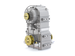
Today I’d like to cover something not all heavy-equipment has: the “power take-off” (PTO) unit. PTOs are auxiliary drives typically found in fuel trucks, drilling rigs, cement mixers, etc. Their existence eliminates the need for a secondary engine to drive components on the chassis. This tip will examine the types of power take-off units, their design, lubricants needed, and their suffering points. The goal of this tip is to bolster our troubleshooting ability in an effort to better support our customers. Remember, using our knowledge to improve the customers’ productivity is the key to successful lubricants marketing. So as usual, grab a beverage, sit back, relax and let’s learn together.
Proper PTO operation is dependent upon the correct gear ratio. The input speed at the PTO must be sufficient to provide the rated output speed and torque for operation of the component driven. Depth of mesh is also essential for proper PTO operation and is monitored as backlash. Backlash is the spacing between the non-contacting, or drive surfaces, of meshed gears. It must be sufficient for expansion caused by the heat of operation. Typical backlash for a power take-off unit is between .006 to .012 inches.
PTOs may be engaged while the vehicle is running or when the drive transmission is in neutral. Transmission powered units are clutch dependent and are only in use when auxiliary power is required.
A power take-off unit should be serviced at the same interval as the component to which it is attached: 250 hours for an engine location and 500 hours for a transmission or differential location. The oil used in a PTO depends upon where it is located. If the PTO is engine or transmission mounted, it will typically use the oil from the host component. If it is mounted on the differential, it will require a small amount of gear oil (ISO VG 68 - 220 EP, SAE 80-90). For the shaft mounted units, the viscosity oil selected depends on the power and speed requirements of the driven component.
As you know, rapid wear leads to early failure and production losses. Wear in a PTO is most often caused by excessive angles at the driveshafts entering or leaving the unit. Regularly check the angularity of these shafts. Proper shaft angles are shown in Figure 2. Other troubleshooting issues include:

Contact us with your PTO requirements. We can assist in choosing the proper PTO and offer competitive pricing. We can supply replacements for the following:
In addition, we offer a wide variety of hydraulic pumps and dump pumps (direct or remote mount applications), and PTO drive shaft kits. Call or e-mail with your requirements.
Also see the DRIVELINE, TRANSMISSION, TRANSFERCASE & PTO PARTS sub section under MILITARY VEHICLE PARTS for PTOs and pumps that are commonly used on military trucks.
“Most importantly, PTOs make fleets money! Typically, the PTO is the first link in the vocational truck’s application chain. The PTO on a truck is the link between the truck’s transmission and the hydraulic pump, blower, or motor doing the work to complete the job. Knowing this, the truck fleet management team needs to install, operate, and maintain it correctly, so the truck is working productively and efficiently,” said Mikel Janitz, Bezares Territory manager & applications engineer.
Bezares is a global manufacturer of PTOs, hydraulic pumps, fittings, tanks, and other mobile power hydraulic components distributed through Eaton in North America.
“The PTO on a truck may only be one component of a much larger picture when it comes to truck fleet management; however, it is paramount to the successful operation of any fleet of hydraulically operated equipment. The PTO converts power from the engine and transmission to an output we can manipulate to drive hydraulic components in various ways to produce a service that generates revenue. This is a simple description of the operation, and we can tie it to fleet management just as easily,” according to Noel Bartlett, field service manager Southwest for Muncie Power Products.
A PTO on a truck, like other components on a truck, require visual inspections and regular maintenance to increase longevity and maintain productivity.
“Productivity drives revenue, therefore, the health and function of the PTO is a valuable and important part of truck fleet management,” Bartlett added. “Having a general understanding of how the PTO is activated, what it does, and how it works helps to reduce downtime, shortens troubleshooting efforts, and provides shop managers and technicians with a higher level of confidence that their fleet is in good working order.”
“A PTO is a gearbox with seals, bearings, and other moving parts. Simple designs and minimal parts equal fewer problems and longer life, resulting in more jobs getting completed on time and budget. Fleet managers focus on cost: the cost of the components, the cost of the entire system, and the total cost of maintenance on a vocational truck. Select a PTO on a truck that is matched correctly to the transmission, application, and operation,” said Janitz of Bezares.
“Gather all the information about the application you are working with before the selection process. A standard PTO on a truck may have a 13 digit or larger part number, and each number or letter is significant. The first determining factor in selecting a PTO is the transmission on the truck,” said Bartlett of Muncie.
“A PTO manufacturer uses the transmission model number to guide you to the correct specification page in their catalog or on their website. There you can find the base model PTO part number needed to work with that transmission. To complete the part number, you need some specific information about the application you are working on. A reliable channel partner or trusted source can help acquire the necessary information to simplify the selection of the proper PTO,” said Bartlett of Muncie.
One factor to consider in selecting a PTO on a truck might come as a surprise, according to Bartlett of Muncie, but is crucial to the process: Find a business partner (PTO supplier) that is as invested in your success as you are.
“Yes, there is a technical side to selecting a PTO but finding a trusted vendor, channel partner, tech support agent, or representative that is willing to guide you through the process can only contribute to the success of the fleet,” he said.
The new Bezares rear-mount PTO incorporates such features as including DIN standard mounting flange and the DIN output all combined with a simple design approach to minimize parts to facilitate ease of installation.
“There are potentially multiple PTOs to choose when building the system. In today’s world, fuel efficiency is a big deal, and managers want to run the truck engine slow to save fuel. This must be balanced with the application torque and horsepower requirements. It also must be balanced with ‘smarter engines’ when emissions are concerned,” said Janitz of Bezares.
“One tip for a continuous application is to select a PTO and ratio that works at a higher engine rpm— approximately 1,100 rpm — and then select the pump to match the required flow rate and pressure. This allows the engine to run effectively as it goes through the regeneration phase,” Janitz added.
“Therefore, utilizing the 8-bolt bottom mount aperture is an ideal solution. The bottom-mount location provides ample room to directly mount the pump to the PTO and facilitates easier hydraulic hose routings,” Janitz said.
“The rear location provides improved ground clearance and more room to directly mount the pump to the PTO and facilitates easier hose routing,” Janitz added.
“The first scenario is a new-build situation where he or she is selecting everything required to drive a hydraulic system or is having a new unit built for the fleet. The second is a repair/replacement scenario where an existing
Be sure to have the transmission model number before you start the process. Bartlett added that it is important to note that a truck’s vehicle identification number (VIN) does not provide the necessary information that a PTO supplier needs to determine the base model for that truck.
“The equipment manufacturer has a list of requirements for the hydraulic system. Make sure to have that information available. This information helps to determine what features are needed to complete the selection such as output shaft size, flange size, activation options, and speed of the PTO,” Bartlett said.
“The challenges here can also be easily overcome with a few quick tips: If the original part number is available on the PTO via a production tag, a PTO can be ordered as a direct replacement. If there is no tag or it is not legible, the manufacturer often engraves the part number under the tag. A flashlight or cell phone camera can help in reading the number,” Bartlett explained. “But, if the PTO part number is not available, the part number of the input gear (the PTO gear that goes into the transmission) will have a part number stamped on it and that can go a long way to identifying the PTO properly.”
“Maintenance can be as simple as looking for leaks and replacing seals, to removing the pump and cleaning and applying grease to the splined pump shaft. Also, if the PTO noise becomes loud or persistent, the PTO should be removed, and inspect the gears for nicks and or metal shavings. If nicks or metal shavings are found, a repair should be completed to ensure continued operation,” said Janitz of Bezares.
Maintenance for a PTO on a truck can also vary based on daily or weekly use, duty cycle times, atmospheric conditions, application, and several other factors.
“For a fleet manager, the maintenance schedule of a truck’s vital fluids, such as engine oil, can be a great time to make a visual inspection of the PTO. Adding the PTO inspection to the regularly scheduled maintenance of the truck reduces downtime and provides the technician the opportunity to talk to the driver about other concerns such as operating noise changes, the functionality of the hydraulic system, changes in duty cycles, etc. This conversation can often help in finding an issue before a downtime failure,” said Bartlett of Muncie.
“The driver knows what the truck and PTO sound like and how they function, and can also identify if something seems to be ‘off.’ Most fleet managers I work with keep a file on each truck and driver’s notes can be maintained here as well,” Bartlett said.
As for specific information about maintenance, each application is different, but there are some common areas to consider when building a maintenance routine for the PTO on a truck.
“First, a solid visual inspection of the entire PTO is a must. This can help identify damage to the housing, surrounding plumbing and wiring, and small leaks, or seepage,” Bartlett said.
“The next, and most likely, inspection would be the mounting of the PTO to the transmission. The bolts holding the PTO to the transmission housing have specific torque requirements to maintain proper backlash and prevent leaks. Inspection of those bolts can be done quickly and prevent future failure as well. If the PTO is ever removed from the transmission visual inspection of the gears and internal components (without disassembly) would give a good snapshot as to the health of the PTO,” Bartlett explained.
“In the past several years, we have seen an increase in the use of automatic transmissions or automatic/manual transmissions. The PTO used in an automatic transmission is often a hot shift, or clutch shift unit, and it operates with an internal clutch pack. These PTOs can be activated in a variety of ways, including while the truck is in operation. This contrasts with the manual transmission PTO that can only be activated when the rotation of the transmission has been stopped,” said Bartlett of Muncie.
“The biggest breakthrough in PTOs has been incorporating better gaskets and seals. Garlock gaskets provide improved leak protection. They perform better than paper gaskets. They are also very dense, which helps reduce creep and facilitates a consistent bolt mounting torque. Viton seal material is one of the best materials used in the industry today. It has ideal physical properties to resist higher heat and aggressive fluid degradation when compared with other common gasket materials,” said Janitz of Bezares.
“The modulated engagement is used to reduce torque spikes on the entire hydraulic system by reducing the start-up speed of the output shaft on the PTO for a moment to allow the system to ramp up to speed slowly. This feature can reduce torque spikes by as much as 70% in some cases and increase the life of the PTO as well as the hydraulic components on the truck,” Bartlett said.
“The Dual Output PTO provides a unique solution, which allows for two PTOs in one eight-bolt location. This saves money, better utilizes space and simplifies installation over a two-PTO (six- and eight-bolt) configuration,” Janitz said.
Lastly, Bartlett noted the growth of plug-and-play wiring harnesses for PTO installation and activation, as well as internal drag brake elements built into the work truck"s PTO.
“Also, technology has given technicians and managers a chance to save time and money because the troubleshooting manuals, installation manuals, and operation manuals specific to the PTO can all be found on manufacturers’ websites and accessible on tablets and cell phones while they are under the truck working,” he said.
“PTO selection can be difficult when it’s not something that you do every day. It is important to have a basic understanding of PTO operation and function, and this can be acquired through trial and error, like so many of the things we do today, or a manager can go online and participate in training through manufactures websites to help them gain additional knowledge,” said Bartlett of Muncie.
“As a fleet manager, you need the truck to be productive, efficient, and reliable. You want it to last a long time, run smooth, and be low maintenance. Selecting the right PTO that gives you the best performance and cost while minimizing and balancing long-term maintenance and repair costs can make a big impact,” said Janitz of Bezares.


 8613371530291