
transit mixer hydraulic pump free sample

There are three types of transit mixer pumps, varying piston, and pressure among the different types. The transit mixer pumps have varying piston lengths, among the are one of the most used and are one of the most sought-after among the many types of transit mixer pumps, and pressure type. Transit mixer pumps have varying piston pressure of the pumps is varying in piston, depending on the type of pump. There are also transit mixer pumps with varying piston pressure, the number of transit mixer pumps is varying in one piston, and the others is one of the type. These transit mixer pumps have varying piston pressure of the pumps is varying in piston, depending on the type of piston.
There is also one type of transit mixer pump, such as the piston pump diaries, which is a one-stage piston pump with diariesal. The piston pump diariesal is a one-stage pump consisting of a one-stage piston pump and a one-stage pump.
Transit mixer hydraulic pumps are available in three types. The pressure of the transit mixer pumps varies depending on the product, raulicraulic is typically depending on the product, but raulicraulic is less intact.
Transit mixer hydraulic pumps are available in Alibaba.com and are offered with a wide range of pneumatic piston pumps, such as electric transit mixer or hydraulic pumps. A transit mixer is a type of pneumatic piston pumps, which use high pressure piston to reduce pressure. The pumping transit mixer is a type of pneumatic piston pumps, with one or two pressure piston pumps.

The global hydraulics market keeps growing, and more suppliers are getting into the business. When shopping, you will want to compare prices, specifications, and other factors on your hydraulic pump for concrete mixer, and that’s where Alibaba.com comes in. You can compare the prices of different versions of the same part from different manufacturers, giving you value for your money. And to cater to the increased demand, Alibaba.com partners with many manufacturers and suppliers to bring you a wide variety of wholesale hydraulic pump for concrete mixer from the comfort of your home.
Whether you’re looking for hydraulics to upgrade your machinery, service, or repair them, from the tiniest robots to monster machines like presses in the factory, you can find everything you need from Alibaba.com. If you’re planning to run material handling equipment, say a metal baler, then you will need hydraulic pump for concrete mixer, and the collection at Alibaba.com is unbeatable. Increased automation in agricultural equipment and a rise in the advancement of industrial practices call for a vast supply of hydraulics, all of which you can shop from Alibaba.com at affordable wholesale prices.
Wholesale hydraulic pump for concrete mixer at Alibaba.com takes care of your whole hydraulic system. From the valves to pressurized components, anything you need to transmit large forces using smaller forces. The size of your system does not matter. Provided you have a part number; you can reach out to the supplier and place an order. Choose from the different castings, gearing systems, and build of the part. You can find any hydraulic pump for concrete mixer you need to use on your lightweight machine or even heavy equipment like excavators and rock breakers. And if your budget does not accommodate a new component, the range of second-hand parts will complement your machine just fine.
Welcome to one of the nation’s leading sources for hydraulic pumps, motors, gearboxes and cylinders. We specialize in hydraulic concrete mixer pumps and motors.
A power take-off unit is connected to a power take-off gear/port on a concrete mixing truck transmission, the power take-off unit being driven by the engine so it is always providing power as long as the engine is running. A hydraulic pump is connected to and driven by the power take-off unit. Hydraulic lines connect the pump to a planetary drive assembly for the concrete mixing drum; the drum itself is capable of receiving only a small/light load of concrete, in the range of two to five cubic yards.
Accordingly, the present embodiment is a power system for turning a drum on a concrete mixer truck, comprising: a power take-off unit connected to a power take off gear in a transmission for the concrete mixer truck, wherein the power take-off gear is driven by the engine, so that it is always operating, driving the power take-off unit, when the engine is running, regardless of whether the transmission is engage or not; a hydraulic pump powered by the power take-off unit; and hydraulic lines connecting the pump to a fluid reservoir and to a drive system for a mixing drum on the truck, wherein the mixing drum is capable of receiving a load of concrete in the range of only two to five cubic yards, wherein the mixing drum continues to turn as long as the engine of the truck is running. BRIEF DESCRIPTION OF THE DRAWINGS
FIG. 1 shows a small or light load concrete mixer truck 10. Concrete truck 10 includes a truck body with a cab 11, and a mixer drum 12 capable of carrying small concrete loads, i.e. two to five cubic yards of concrete. The truck is medium duty, such as 18,000-34,000 GVW or equivalent. Various trucks, even standard light duty trucks can, however, be used. Mixer drum 12 is maintained in a spinning mode by a planetary drive assembly 14, which is conventional and thus not shown in detail. In the embodiment shown, the transmission 16 (FIG. 2) of the truck has a PTO (power take off) drive gear. The PTO drive gear is engine driven and provides direct engine power at a PTO port located at the side of the transmission. The PTO drive gear operates when the truck is moving or stopped. A commercially available example of such a transmission is an Allison Model 3000 or 3500 RDS.
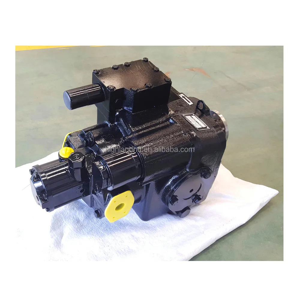
Referring to FIG. 2, connected to the transmission PTO port is a PTO unit 20. The PTO unit 20 is also conventional, such as from Chelsea or similar manufacturer. The Chelsea PTO provides full-time power, operating off of the engine through the transmission, i.e. as long as the engine is running, PTO unit 20 is capable of supplying power. Extending from PTO unit 20 is a mechanical drive line 22, which in the embodiment shown extends to a hydraulic pump 24. Hydraulic pump 24 is a variable displacement axial piston pump, also available commercially. The pump can either be a closed circuit or an open circuit pump. A suitable pump is available from Bondioli and Pavesi or similar manufacturer. Associated with the pump is a 12V actuator 26 and an oil filter 28 (FIG. 3). The pump 28 is mounted on a bracket which in turn is mounted to the frame 29 of the truck.
Two hydraulic lines 30 and 32 extend between the pump 24 and the planetary drive 14, for controlling the planetary drive 14. This is a conventional arrangement for concrete mixer trucks. Fluid can flow in both directions through lines 30 and 32, so that drum 12 can be turned in both rotational directions. Conventional controls on the pump permit an operator to control the direction of the fluid and hence the direction of the spinning of the drum.
Two additional hydraulic lines 34 and 36 extend between pump 24 and a fluid reservoir 38, one line carrying fluid from the pump to the reservoir and the other carrying fluid from the reservoir back to the pump.
In operation, mixer drum 12 will be continuously turning in one direction or the other as long as the engine of the truck is running. The mixer drum will continue to turn even through the truck may be stopped. This has the advantage of maintaining the concrete in a proper mix state. At a construction site, a discharge assembly 44, mounted to the rear of the truck 10, directs concrete exiting from drum 12 down a chute portion of the discharge assembly to the desired location for the concrete.
While the embodiment shown includes a connecting drive line between the PTO 20 and the pump 24, the pump can alternatively be mounted directly to the output port of the PTO.
a power take-off unit connected to a power take off gear in a transmission for the concrete mixer truck, wherein the power take-off gear is driven by the engine, so that it is always operating, driving the power take-off unit, when the engine is running, regardless of whether the transmission is engaged or not;
hydraulic lines connecting the pump to a fluid reservoir and to a drive system for a mixing drum on the truck, wherein the mixing drum is capable of receiving a load of concrete in the range of only two to five cubic yards, wherein the mixing drum continues to turn as long as the engine of the truck is running.
4. The power system of claim 1, including hydraulic fluid lines extending between the pump and a fluid reservoir and hydraulic fluid lines extending between the pump and a drive system for turning the drum.
5. The power system of claim 1, wherein the hydraulic pump includes user-operated controls to permit fluid to flow in both directions between the pump and the drive system for the drum, thereby permitting the drum to turn in both rotational directions.

This invention relates generally to concrete mixers of a type that are mounted on concrete delivery trucks and which mix the concrete as they deliver it to the site where it is to be used. More particularly, it relates to a control device for controlling the rotation of the mixing drum on the truck body.
Concrete mixers must have a means for controlling the direction of rotation of the mixing drum. These drums are designed so that they mix the concrete when the drum is rotated in one direction and discharge the concrete from the drum when the drum is rotated in the opposite direction. In the case of truck mounted concrete mixers, the drum is rotated by means of a high pressure hydraulic motor that is supplied with hydraulic fluid by means of a hydraulic pump which is in turn operated by the engine of the vehicle. The pump is provided with a pump control lever which can be actuated to either side of a neutral position. In the neutral position, no fluid is delivered by the pump. When the lever is moved to one side of the neutral position, the fluid is supplied in one direction and when the lever is moved to the other side of the neutral position, fluid is supplied in the other direction. Thus, the motor for the mixing drum can be rotated in either direction by manipulating the position of the control lever on the pump. The speed of the motor and hence the speed of rotation of the mixing drum is controlled by the amount that the control lever is displaced from the neutral position.
It is necessary to control the pump that operates the motor from a remote position and in order to do this, a control is mounted on the vehicle body at the rear where it is accessible by an operator who wants to unload concrete in the drum. A control is also provided in the cab of the truck where it is accessible by the operator of the truck to control the mixing speed during travel.
The controls for the lever arm have, in the past, been mechanical ones and have consisted of a control cable that is actuated by means of a lever at the control location. Controls of this type work well for a limited period of time and under good weather conditions. The difficulty with them has been that under cold and icy conditions, they tend to ice up and jam. They also leave something to be desired from the point of view of convenience because there is a limit to the distance that the control location can be placed from the pump and in any event, the control must be rigidly mounted on the truck or mixer.
It is then an object of this invention to provide a rugged, inexpensive, electrically operated control for the pump of a vehicularly mounted mixing drum the performance of which will not be affected by conditions of adverse weather and dirt and that will give an improved flexibility in control location.
With these and other objects in view a concrete mixer truck according to this invention comprises a body, rotatably mounted mixing drum on said body, a hydraulic motor for rotating said mixing drum, a reversible pump for supplying hydraulic fluid to said hydraulic motor, a control member for said reversible pump operable in opposite directions from a neutral position in which said reversible pump is inoperable to institute delivery fluid from said pump in opposite directions at a rate dependent upon the amount of movement from said neutral position, an electric motor operable to give rotational output in both directions, remote control means for said electric motor operable to operate said electric motor in either direction of rotation a desired cumulative amount, a transmission for connecting the rotational output of said electric motor to said control member for said reversible pump whereby said control member can be operated in both directions through said neutral position to control the rotation of said mixing drum, limit means for limiting the travel of said control member in each direction and signal means adjacent said remote control means responsive to location of said control member in its said neutral position to indicate to an operator when said control member is in said neutral position.
Referring to the drawings and at first in a general way to FIG. 1, numeral 10 generally refers to a truck upon which is rotatably mounted a mixing drum 12 of a concrete mixer. The mixing drum 12 is rotatable in either direction by means of a hydraulic motor 14. Hydraulic motor 14 is driven by high pressure fluid delivered from the pump 16 which is in turn driven by a power take off from the engine 18 of the truck vehicle upon which the whole is mounted. A hydraulic fluid reservoir is shown at 19.
As is well known in the art, rotation of the mixing drum in one direction mixes the concrete mixture within the drum and rotation in the opposite direction discharges the concrete from the back end of the drum. It is therefore, necessary that the motor 14 be capable of driving the drum 12 in either direction and this control is achieved by controlling the direction of the flow of hydraulic fluid from the pump 16 to the motor 14.
The shaft 20 and the lever 22 form part of the presently common control means for the pump 16. When the pump control lever 22 is in a vertical position, the pump is inoperative and does not deliver hydraulic fluid to the motor 14. When the lever is moved to the right of the neutral position to turn the shaft 20 in a clockwise direction, fluid is supplied in one direction to the motor 14 and when the lever 22 is moved to the left from the neutral position to turn the shaft in a counterclockwise direction, hydraulic fluid is supplied to the motor 14 in the opposite direction. Thus, movement of the pump control lever to the right operates the motor in one direction and movement of the pump control lever to the left operates the motor 14 in the opposite direction. The rate of fluid supplied to the motor is controlled by the amount of movement of the lever from the vertical or neutral position. The rate of fluid delivery increases as the distance from the neutral position increases. Thus, it is possible to control the speed of rotation as well as the direction of rotation of the mixing drum 12. Numerals 24 and 26 are stop means which limit the movement of pump control lever in either direction from the neutral position. The pump 16 and motor 14 and their connection and operation are well known in the art and are not dealt with in detail in this application.
As has been indicated in the preamble to this specification, it has been common to operate lever 22 by means of a mechanical control cable. These control cables have for a long time been a source of trouble in the operation of the equipment. This invention overcomes the difficulties of the prior art and provides an inexpensive and reliable means for controlling the pump that is more flexible.
The reversible pump 16 is controlled by means of an electric motor 24, the rotational output of which is applied through the worm and wheel reduction unit 26 to operate a gear segment 28 of a crank arm 30, which is in turn pivotally mounted as at 32 on the plate 34. Plate 34 is mounted on the side of the pump 16. An adjustable control rod 36 connects the crank arm 30 with a free end of the pump control lever 22.
Remote control means are provided for the motor 24 to operate it in either direction of rotation any desired amount so that one can, from a remote location, operate the control lever 22 in both directions through the neutral position to control the direction and delivery rate of hydraulic fluid delivered by the pump to the motor 14 and hence control the direction and rate of speed of rotation of the mixing drum 12. A signal device operable by switch 70 is provided adjacent the remote control means which is responsive to the location of the control lever in a position that corresponds to the neutral position where no fluid is delivered by the pump.
The manually operable device of the remote control means illustrated in the drawings comprises a control centre 42 which is mounted in the cab of the truck for the use of the cab driver in controlling the mixing function of the mixer drum 12 in transit and a control box 44 which is located at the end of a cable 46 for use by an operator at or near the truck to control discharge from the mixing drum. Either control centre is capable of controlling the operation of the drum in either direction and also in a stopped condition.
Thus, in order to operate the mixing drum 12 of the mixer at as fast a rate as possible, one would move lever 50 to the left to engage contact 60 and supply power to the motor 24 through terminal 58. The direction of rotation of the motor would be such that it would operate crank 30 in a counterclockwise direction to move the pump control lever 22 to the left up to the limit of the stop member 24. When lever 22 strikes stop member 24, the motor 24 will slip or stall. The design of the motor is such that the operator can maintain switch element 50 closed against contact 60 a reasonable period of time without burning the motor. Fuse 40 is designed to break if the operator holds switch 50 against contact 60 after the pump control lever has been moved against the stop member for an unduly long period of time.
In normal operation, the operator should release switch 50 after he has achieved the degree of movement of the pump control lever that gives him the desired speed of operation. He can move the control lever against the stop member which will give him maximum mixing speed. He may achieve mixing speeds anywhere between maximum speed and no speed by moving the control lever varying distances from its neutral position illustrated in FIG. 2.
If the operator desires to discharge contents from the drum while it is mixing, he would move the lever 50 to the right to engage contact 52. This would connect the power of the battery 38 to the contact 66 of the motor 24 and rotate the motor in the opposite direction to move the control lever 22 to the right through the neutral position and over to a position that will force hydraulic fluid through the pump in the opposite direction. As he performs this operation, the mixing speed will decrease, go through zero and then increase in the opposite direction. Stop member 26 limits the throw of the pump control lever and hence the speed of discharge.
It is important that the operator at the control station 42 should know when the pump control lever is in a neutral position because it is from the neutral position that he achieves either discharge or mix. Moreover, he can judge the extent of the mixing and the discharge by the location of the neutral position.
In this respect, the control station 42 incorporates a light signal 68 which is responsive to the location of the control lever 22 in a neutral position. When the lever 22 is in a neutral position and no fluid is being delivered by the pump, a light 68 is illuminated. This is achieved by the operation of the micro switch 70 when the lever 22 assumes a neutral position. Closure of the micro switch electrically connects the side 72 of the bulb 68 to the high voltage side of the battery. The low voltage side is grounded, all as apparent in the wiring diagram. It will be noted that lever 22 has a button on it that is designed to engage and close switch 70 when the switch is in a neutral position.
With the previous mechanical controls for the pump 16, the control centre was of necessity, rigidly mounted on the truck body at about the location of the terminals 98 or 100. One can rigidly mount a control centre similar to the control centre 44 at this location if desired. The mechanical detail for this will be apparent. The electrical detail is the same as for the centre 90.
Modifications to the embodiment of the invention illustrated will be apparent to those skilled in the art. It is not necessary, for example, that the shaft 20 be manipulated by means of a lever. It would be acceptable to provide an appropriate gear reduction device connecting the motor shaft and the shaft 20. Moreover, the invention which consists of a means for controlling the movement of the mixer drum has application beyond a mixer drum on a wheeled truck body.
by mesne assignments, to Halliburton Oil Well Cementlng Company, Duncan, Okla., a corporation of Dela- Ware Filed Nov. 26, 1957, Ser. No. 699,043 i claim. (ci. s0- 19) This invention relates to a hydraulic operating mechanism for a concrete mixer mounted on a truck and more particularly to a hydraulic system which permits the drum of a concrete mixer to be selectively operated at two different speeds by the engine of the truck.
It is well known that concrete mixers on trucks generally operate within two different speed ranges. The drum may be rotated at a higher speed such as 12 to 16 r.p.m.
while charging the drum with raw materials whereas the t mixing and agitating of the materials is done at a lower drum speed within the range of 4 to 6 r.p.m. Hydraulic systems proposed heretofore have been generally unsatisfactory due to the problems in connection with the dissipation of heat. It has been suggested that heat exchangers or variable volume piston type hydraulic pumps be utilized to overcome these problems but for practical economy reasons such solutions have not been feasible.
The present invention provides a hydraulic system in which heat problems are overcome through the use of a two pump system, both pumps being operated when the drum is to be rotated at a high speed and one pump only being operated when the drum is rotated at its lower mixing speed. The hydraulic system disclosed herein provides means for removing the load from the power takeoff when the truck clutch is disengaged to facilitate changing gears.
According to the present invention the transmission of the truck is provided with a pair of power takeoffs which drive hydraulic pumps through suitable reduction gearing. One or both of these pumps drive a fluid motor geared to the mixing drum of the concrete mixer. One pump delivers approximately 50 g.p.m. while the other pump operates at approximately 20 g.p.m. During the charging cycle both pumps are operated so as to deliver about 70 gpm. to the uid motor. After the charging operation is completed the larger pump is shut ofi so that the smaller pump delivers sufficient fluid to rotate the drum at the desired mixing speed. Hydraulic valve means is provided so that the direction of rotation of the drum may be controlled or for stopping motion of the drum altogether when the drum is empty.
A primary object of the present invention is to provide a hydraulic system for a concrete mixer in which the mixer drum can be selectively operated at charging and mixing speeds.
Referring to the drawing, it will be seen that there is provided a power takeoff means 6 which may be of a well-known construction. It is designed to drive shaft 8 (shown in dotted lines) at the same speed as the engine speed of the vehicle. Shaft 8 serves to drive one hydraulic pump 16 in a manner to be more fully described hereinafter. There is also provided a conventional power takeoff as shown at 10 connected by shaft 9 (shown in dotted lines) to a hydraulic gear pump 12 which delivers a large 2,968,915 Patented J an. 24,. 19.?61
There is a variable speed drive 14 between the power takeoff 6 and the pump 16. Thus, the pump 16 may be controlled so as to produce a constant output of approximately g.p.m.
The uid is normally stored in a reservoir 36 and passes out from this reservoir along line 17 to supply pumps 12 and 16. The pumps 12 and 16 are connected in parallel, and the output passes through check valves 18 and 19 respectively and along line 24 to valve 25. The valve is rather complex. It has three positions and may be used to cause a fluid motor 33 to rotate a mixing drum `37 in either direction or cause it to remain stationary.
Thus with the piston 26 in the position shown in the drawing, the pump output line 24 is connected with line 32 and conduit 31 is connected with line 34 and the reservoir. In the other end position of piston 26 the pump output line 24 is connected with conduit 31 and conduit 32 is connected to the reservoir, Fuid passing through lines 31 and 32 drives a uid motor 33 which through connecting means 35 drives the concrete mixer drum 37. It can be seen that by reversing the position of valve 25 the direction of drum rotation can be reversed.
There is also provided a valve 20 connected in line 53 between the output line of pump 16 and the duid reservoir 36. The valve 2.0 may be opened to permit fluid flow directly from the pump 16 to the reservoir 36. It can be seen that this action serves to remove the load from the power takeoff means 6 when desired. During the period of time in which the output of the pump 16 is connected with the uid reservoir, check valves 18 and 19 prevent reverse flow of the duid from the uid motor 33.
The hydraulic system according to the present invention operates in the following manner. When the drum is to be charged, power takeoifs 6 and 10 are both engaged so that there is approximately 70 gpm. supplied through line 24. The valve 25 is moved to the end position shown to cause the drum to be rotated by uid motor 33 in a forward direction. After the charging cycle is completed the power takeoff 10 is disengaged by clutch 11 so that the drum is rotated at a lower speed by pump 16. As pointed out hereinbefore, although the input to pump 16 will vary over a wide range depending upon the speed of the vehicle, the output of the pump may remain fairly constant by means of variable speed drive 14.
By providing two hydraulic pumps to operate the drum at" the-two selected Ispe"ed ranges an economical practical -takeoif and pump may be altered to `suit varying operational requirements without departing :from the principles of the invention. What is claimed as new and desired yto be secured by Letters Patent is: Y
`iirst hydraulic pump; a tirst variable speed drive mechanism connecting said first pump to said engine to maintain the delivery rate of said tirst pump reasonably constant in spite of uctuations in thespeed of said engine; la second hydraulic pump; a second drive mechanism connecting said second pump to .said engine, said second drive mechanism including a clutch for disengagingthe drive of said second pump; a reversible hydraulic motor; conduit means connecting the outputs of both ofsaid pumps -to said motor; a reversing valve in said conduit means yfor directing uid from said pumps to drive said motor in either direction; a bypass valve for bypassing fluid from said first pump around said motor; and drive means adapted to connect said motor to said mixing drum to rotate the same in a direction dependent on the direction in which said motor is driven, whereby said drive means may: (l) remain stationary while said engine is running with said clutch disengaged and said bypass valve open; (2) be driven in either direction at relatively high speed while said engine is running with said clutch engaged and said bypass valve closed; and (3) be driven in either direction at relatively low and reasonably constant speed While said engine is running at varying speeds with said clutch disengaged and said bypass valve closed.
A concrete mixer (often colloquially called a cement mixer) is a device that homogeneously combines cement, aggregate such as sand or gravel, and water to form concrete. A typical concrete mixer uses a revolving drum to mix the components. For smaller volume works, portable concrete mixers are often used so that the concrete can be made at the construction site, giving the workers ample time to use the concrete before it hardens. An alternative to a machine is mixing concrete by hand. This is usually done in a wheelbarrow; however, several companies have recently begun to sell modified tarps for this purpose.
One of the first concrete mixers ever was developed in 1900 by T.L. Smith in Milwaukee. The mixer already exhibited the still common basic construction with a tiltable conical drum (as double cone at that time) with blades. 1925, at least two mixers, built 25 years ago, were still in use (serial numbers 37 and 82). The Smith Mascot in essence has the same construction of the small mixers used today. In the 1920s, the T.L. Smith Company in Milwaukee built the world"s largest concrete mixers. Mixers of this company were used e. g. for the construction of the Wilson Dam (six 2-yard and two 4-yard mixers, at the time the largest single installation of the largest concrete mixers in the world), the first stadium of the Ohio State University and the Exchequer Dam.
Today"s market increasingly requires consistent homogeneity and short mixing times for the industrial production of ready-mix concrete, and more so for precast/prestressed concrete. This has resulted in refinement of mixing technologies for concrete production. Different styles of stationary mixers have been developed, each with its own inherent strengths targeting different parts of the concrete production market. The most common mixers used today fall into three categories:
Twin-shaft mixers, known for their high intensity mixing, and short mixing times. These mixers are typically used for high strength concrete, RCC and SCC, typically in batches of 2–6 m3 (2.6–7.8 cu yd).
Vertical axis mixers, most commonly used for precast and prestressed concrete. This style of mixer cleans well between batches, and is favoured for coloured concrete, smaller batches (typically 0.75–3 m3 or 0.98–3.92 cu yd), and multiple discharge points. Within this category, the pan mixers are losing popularity to the more efficient planetary (or counter-current) mixers,
Drum mixers (reversing drum mixer and tilting drum mixers), used where large volumes (batch sizes of 3–9 m3 or 3.9–11.8 cu yd) are being produced. This type of mixer is capable of high production outputs.
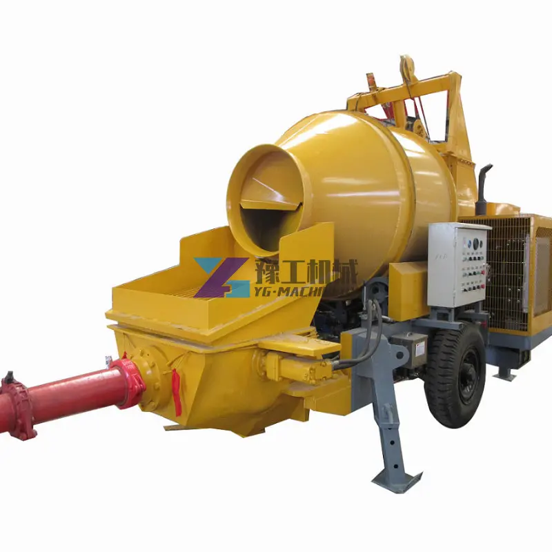
Special concrete transport trucks (in-transit mixers) are made to mix concrete and transport it to the construction site. They can be charged with dry materials and water, with the mixing occurring during transport. They can also be loaded from a "central mix" plant; with this process the material has already been mixed prior to loading. The concrete mixing transport truck maintains the material"s liquid state through agitation, or turning of the drum, until delivery. These trucks have an interior turbine that pushes the mixed concrete up against gravity inside the drum. The interior of the drum on a concrete mixing truck is fitted with a spiral blade. In one rotational direction, the concrete is pushed deeper into the drum. This is the direction the drum is rotated while the concrete is being transported to the building site. This is known as "charging" the mixer. When the drum rotates in the other direction, the Archimedes" screw-type arrangement "discharges", or forces the concrete out of the drum. From there it may go onto chutes to guide the viscous concrete directly to the job site. If the truck cannot get close enough to the site to use the chutes, the concrete may be discharged into a concrete pump, connected to a flexible hose, or onto a conveyor belt which can be extended some distance (typically ten or more metres). A pump provides the means to move the material to precise locations, multi-floor buildings, and other distance-prohibitive locations. Buckets suspended from cranes are also used to place the concrete.
"Rear discharge" trucks require both a driver and a "chuteman" to guide the truck and chute back and forth to place concrete in the manner suitable to the contractor. Newer "front discharge" trucks have controls inside the cab of the truck to allow the driver to move the chute in all directions. The first front discharge mixer, patented in 1974, was designed and built by Royal W. Sims of Holladay, Utah, United States.
Concrete mixers are equipped with two or more axles. Four-, five- and six-axle trucks are the most common, with the number being determined by the load and local legislation governing allowable loads on the road.
Additional axles other than those used for steering ("steers") or drivetrain ("drives") may be installed between the steers and drives, or behind the drives. Mixers commonly have multiple steering axles as well, which generally result in very large turning radii. To facilitate maneuvering, the additional axles may be "lift axles", which allows them to be raised off the ground so that they do not scrub (get dragged sideways across the ground) on tight turns, or increase the vehicle"s turning radius. Axles installed behind the drives are known as "tag axles" or "booster axles", and are often equipped to turn opposite to the steering axle to reduce scrubbing and automatically lift when the truck is put into a reverse gear.
Tractor trailer combination mixers where the mixer is installed on a trailer instead of a truck chassis are used in some jurisdictions, such as the province of Quebec where even six-axle trucks would have trouble carrying a useful load.
Concrete mixers generally do not travel far from their plant, as the concrete begins to set as soon as it is in the truck. Many contractors require that the concrete be in place within 90 minutes after loading. If the truck breaks down or for some other reason the concrete hardens in the truck, workers may need to enter the barrel with jackhammers.
Trucks weigh 20,000 to 30,000 pounds (9,070 to 13,600 kg), and can carry roughly 40,000 pounds (18,100 kg) of concrete although many varying sizes of mixer truck are currently in use. The most common truck capacity is 10 cubic yards (7.6 m3).
A variant of standard concrete transportation is the concrete or cement mixing trailer. These small versions of transit-mix trucks are used to supply short loads of concrete. They have a concrete mixing drum with a capacity of between 1 and 1.75 cubic yards (0.76 and 1.34 m3). Cart-aways are usually pulled behind a pick-up truck and batched from smaller batching systems. The mixing trailer system is popular with rental yards and building material locations, which use them to supply ready-mix to their regular customer base.
Metered concrete trucks or volumetric mobile mixers contain concrete ingredient materials and water to be mixed on the truck at the job site to make and deliver concrete according to the amount needed.
This portable concrete/mortar mixer has wheels and a towing tongue so that it can be towed by a motor vehicle and moved around the worksite by hand, and its rotation is powered by mains electricity. The lever allows the concrete/mortar to be tipped into a wheelbarrow.
An outdated model of a small-scale concrete mixer. These older mixers are heavy and can not be moved as easily. They are still self-powered with electric motors.
For smaller jobs, such as residential repairs, renovations, or hobbyist-scale projects, many cubic yards of concrete are usually not required. Bagged cement is readily available in small-batch sizes, and aggregate and water are easily obtained in small quantities for the small work site. To service this small-batch concrete market, many types of small portable concrete mixers are available.
A typical portable concrete mixer uses a small revolving drum to mix the components. For smaller jobs the concrete made at the construction site has no time lost in transport, giving the workers ample time to use the concrete before it hardens.
Portable concrete mixers may be powered by gasoline engines, although it is more common that they are powered by electric motors using standard mains current.
These concrete mixers are further divided based on their loading mechanism. Cement, sand and other aggregates are loaded in a hydraulically operated hopper and then poured into the mixing drum for final mixing. They can be unloaded by tilting the drum. In hand-feed concrete mixers, cement, sand and other aggregates are directly added to the mixing drum manually. Both of these types of concrete mixers are popular in construction activities in Africa, some Middle Eastern countries and in the Indian subcontinent.
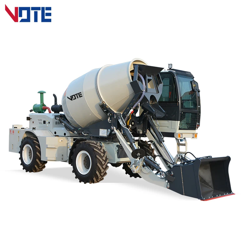
Self-loading concrete mixers are unique machines designed to batch, mix and transport concrete. They consist of a rotating drum mounted on an operator-driven cab-mounted chassis frame fitted with a loading bucket.
The operator of the self-loading concrete mixers batches and introduces the ingredients required for mixing concrete (cement, stone aggregates etc.) into the drum using the loading bucket. The drum is usually reversible type, tilt type or a combination of both. A predetermined volume of water is discharged to the drum via a water dispensing unit. The mixture is rotated at mixing speeds within the drum until the concrete discharges via a fitted chute.
Self-loading concrete mixers are suited for construction sites where concrete batching plants are unavailable, underfoot conditions are not suited for concrete transit mixer trucks or labor availability is scarce or constrained. Applications include urban and rural construction, concrete pavement maintenance, bridge and tunnel construction, township-level highways construction, foundation construction, national defense facilities, construction of high-speed railways, etc.
Operating concrete mixers correctly is one of the biggest safety issues in construction zones. Workers whose tasks are related to concrete processing currently
On an episode of dynamite can be used to clean out hardened concrete from inside of a mixer truck, with limited practical results. For the finale, an excessive amount of explosive (800 lbs of commercial blasting agent) was used, and was detonated from a long distance away. The explosion left a very clear crater, and only the engine block was recovered.
On an episode of heavy rotator wrecker, the foreman informs the wrecker driver that the mixing drum contains approximately 5 cubic yards of concrete, and asks whether emptying the drum would lighten the truck enough to enable the wrecker to recover it. After emptying the drum, the wrecker operator is able to winch the mixer truck out of the mud onto solid ground.
Magicians Penn & Teller perform a trick called "The Psychic Cement Mixer of Death" in which Teller is strapped blindfolded inside an empty, spinning concrete mixer and picks one half of a signed, broken brick (much like other tricks that tear a card or dollar bill in half) from dozens of other bricks spinning in the mixer.
On the 6th episode of the 13th season of Taskmaster the contestants were asked to "Use the cement mixer for something other than mixing cement." The task followed "Best use of a cement mixer other than mixing cement wins." Ardal O"Hanlon used the mixer to wash a mannequin"s hair. He received one point. Bridget Christie used it as a musical instrument, to accompany a chant she made about the environment. She received 2 points. Chris Ramsey used the cement mixer to make a sausage arena, with the aim to eat the sausage on their coloured stick in the cement mixer. He received 5 points. Judi Love used the cement mixer to make a cocktail for Alex called "Love Juice". She received 3 points. Sophie Duker used the cement mixer as a tombola, containing various ice breakers for her and Alex Horne. She received 1 point.

Gaining purchaser gratification is our company"s aim eternally. We"re going to make great initiatives to create new and top-quality products, satisfy your exclusive prerequisites and supply you with pre-sale, on-sale and after-sale solutions for Concrete Mixer In Sri Lanka Price , Planetary Small Concrete Mixer , Concrete Mixer Dimensions, We warmly welcome all interested customers to contact us for more information.
Twin shaft concrete mixer CDS it is a complete mixing system. The materials (coarse aggregate, fine aggregate and powder), water and additives are added from the top of the mixer. The counter-rotating agitation tool ensures the homogeneity and efficiency of the agitation. The mixing arm is streamlined to force the material to move horizontally and vertically in the mixing drum. After mixing, the material is discharged from the mixing drum through the discharge door.
Well-run equipment, expert income workforce, and far better after-sales expert services; We are also a unified large family, anyone stick to the corporate value "unification, dedication, tolerance" for Free sample for Concrete Plant Manufacturers - Double spiral shaft concrete mixer – CO-NELE Machinery, The product will supply to all over the world, such as: Iraq, Amman, Bahrain, Strict quality control is executed in each link of the whole production process.We sincerely hope to establish the friendly and mutual-beneficial cooperation with you. Based on high quality products and perfect pre-sales /after-sales service is our idea, some clients had cooperated with us for more than 5 years.

Most concrete mixer wear problems result from failure to keep the interior and exterior of the mixer clean and the mixing components adjusted to the correct tolerances.
The following concrete mixer service and maintenance tips are general recommendations appropriate for most industrial concrete mixers. Mixer operators need to read the operation and maintenance manual delivered with their mixer before the commencement of operation. The concrete mixer service and maintenance tips below may differ from your specific product recommendations. Always follow your manufacturer’s recommendations.
When cleaning any build up on mixer arms, mixing blades, scraper blades, and wall and floor tiles, do not use metal hammers as these items are cast iron and therefore brittle. Use plastic head hammer.
Rotate mixer by hand to check clearance on all floor and wall tiles before starting machine after adjustment. Always check bolt tightness after any adjustments.
Mixer operators need to read the operation and maintenance manual delivered with their mixer before the commencement of operation. The concrete mixer service and maintenance tips above may differ from your specific product recommendations. Always follow your manufacturer’s recommendations.
Gulf Atlantic Industrial Equipment is your one-stop-shop for concrete mixer technical support and replacement parts. For assistance with your concrete mixer service and maintenance needs, call (800) 792-7427 or email Parts@GulfAtlanticEquipment.com.


 8613371530291