
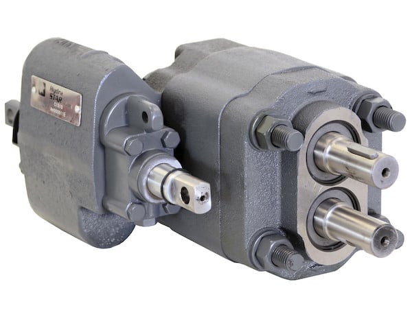
truck mounted hydraulic pump free sample

Hydraulic pumps are mechanisms in hydraulic systems that move hydraulic fluid from point to point initiating the production of hydraulic power. Hydraulic pumps are sometimes incorrectly referred to as “hydrolic” pumps.
They are an important device overall in the hydraulics field, a special kind of power transmission which controls the energy which moving fluids transmit while under pressure and change into mechanical energy. Other kinds of pumps utilized to transmit hydraulic fluids could also be referred to as hydraulic pumps. There is a wide range of contexts in which hydraulic systems are applied, hence they are very important in many commercial, industrial, and consumer utilities.
“Power transmission” alludes to the complete procedure of technologically changing energy into a beneficial form for practical applications. Mechanical power, electrical power, and fluid power are the three major branches that make up the power transmission field. Fluid power covers the usage of moving gas and moving fluids for the transmission of power. Hydraulics are then considered as a sub category of fluid power that focuses on fluid use in opposition to gas use. The other fluid power field is known as pneumatics and it’s focused on the storage and release of energy with compressed gas.
"Pascal"s Law" applies to confined liquids. Thus, in order for liquids to act hydraulically, they must be contained within a system. A hydraulic power pack or hydraulic power unit is a confined mechanical system that utilizes liquid hydraulically. Despite the fact that specific operating systems vary, all hydraulic power units share the same basic components. A reservoir, valves, a piping/tubing system, a pump, and actuators are examples of these components. Similarly, despite their versatility and adaptability, these mechanisms work together in related operating processes at the heart of all hydraulic power packs.
The hydraulic reservoir"s function is to hold a volume of liquid, transfer heat from the system, permit solid pollutants to settle, and aid in releasing moisture and air from the liquid.
Mechanical energy is changed to hydraulic energy by the hydraulic pump. This is accomplished through the movement of liquid, which serves as the transmission medium. All hydraulic pumps operate on the same basic principle of dispensing fluid volume against a resistive load or pressure.
Hydraulic valves are utilized to start, stop, and direct liquid flow in a system. Hydraulic valves are made of spools or poppets and can be actuated hydraulically, pneumatically, manually, electrically, or mechanically.
The end result of Pascal"s law is hydraulic actuators. This is the point at which hydraulic energy is transformed back to mechanical energy. This can be accomplished by using a hydraulic cylinder to transform hydraulic energy into linear movement and work or a hydraulic motor to transform hydraulic energy into rotational motion and work. Hydraulic motors and hydraulic cylinders, like hydraulic pumps, have various subtypes, each meant for specific design use.
The essence of hydraulics can be found in a fundamental physical fact: fluids are incompressible. (As a result, fluids more closely resemble solids than compressible gasses) The incompressible essence of fluid allows it to transfer force and speed very efficiently. This fact is summed up by a variant of "Pascal"s Principle," which states that virtually all pressure enforced on any part of a fluid is transferred to every other part of the fluid. This scientific principle states, in other words, that pressure applied to a fluid transmits equally in all directions.
Furthermore, the force transferred through a fluid has the ability to multiply as it moves. In a slightly more abstract sense, because fluids are incompressible, pressurized fluids should keep a consistent pressure just as they move. Pressure is defined mathematically as a force acting per particular area unit (P = F/A). A simplified version of this equation shows that force is the product of area and pressure (F = P x A). Thus, by varying the size or area of various parts inside a hydraulic system, the force acting inside the pump can be adjusted accordingly (to either greater or lesser). The need for pressure to remain constant is what causes force and area to mirror each other (on the basis of either shrinking or growing). A hydraulic system with a piston five times larger than a second piston can demonstrate this force-area relationship. When a force (e.g., 50lbs) is exerted on the smaller piston, it is multiplied by five (e.g., 250 lbs) and transmitted to the larger piston via the hydraulic system.
Hydraulics is built on fluids’ chemical properties and the physical relationship between pressure, area, and force. Overall, hydraulic applications allow human operators to generate and exert immense mechanical force with little to no physical effort. Within hydraulic systems, both oil and water are used to transmit power. The use of oil, on the other hand, is far more common, owing in part to its extremely incompressible nature.
Pressure relief valves prevent excess pressure by regulating the actuators’ output and redirecting liquid back to the reservoir when necessary. Directional control valves are used to change the size and direction of hydraulic fluid flow.
While hydraulic power transmission is remarkably useful in a wide range of professional applications, relying solely on one type of power transmission is generally unwise. On the contrary, the most efficient strategy is to combine a wide range of power transmissions (pneumatic, hydraulic, mechanical, and electrical). As a result, hydraulic systems must be carefully embedded into an overall power transmission strategy for the specific commercial application. It is necessary to invest in locating trustworthy and skilled hydraulic manufacturers/suppliers who can aid in the development and implementation of an overall hydraulic strategy.
The intended use of a hydraulic pump must be considered when selecting a specific type. This is significant because some pumps may only perform one function, whereas others allow for greater flexibility.
The pump"s material composition must also be considered in the application context. The cylinders, pistons, and gears are frequently made of long-lasting materials like aluminum, stainless steel, or steel that can withstand the continuous wear of repeated pumping. The materials must be able to withstand not only the process but also the hydraulic fluids. Composite fluids frequently contain oils, polyalkylene glycols, esters, butanol, and corrosion inhibitors (though water is used in some instances). The operating temperature, flash point, and viscosity of these fluids differ.
In addition to material, manufacturers must compare hydraulic pump operating specifications to make sure that intended utilization does not exceed pump abilities. The many variables in hydraulic pump functionality include maximum operating pressure, continuous operating pressure, horsepower, operating speed, power source, pump weight, and maximum fluid flow. Standard measurements like length, rod extension, and diameter should be compared as well. Because hydraulic pumps are used in lifts, cranes, motors, and other heavy machinery, they must meet strict operating specifications.
It is critical to recall that the overall power generated by any hydraulic drive system is influenced by various inefficiencies that must be considered in order to get the most out of the system. The presence of air bubbles within a hydraulic drive, for example, is known for changing the direction of the energy flow inside the system (since energy is wasted on the way to the actuators on bubble compression). Using a hydraulic drive system requires identifying shortfalls and selecting the best parts to mitigate their effects. A hydraulic pump is the "generator" side of a hydraulic system that initiates the hydraulic procedure (as opposed to the "actuator" side that completes the hydraulic procedure). Regardless of disparities, all hydraulic pumps are responsible for displacing liquid volume and transporting it to the actuator(s) from the reservoir via the tubing system. Some form of internal combustion system typically powers pumps.
While the operation of hydraulic pumps is normally the same, these mechanisms can be split into basic categories. There are two types of hydraulic pumps to consider: gear pumps and piston pumps. Radial and axial piston pumps are types of piston pumps. Axial pumps produce linear motion, whereas radial pumps can produce rotary motion. The gear pump category is further subdivided into external gear pumps and internal gear pumps.
Each type of hydraulic pump, regardless of piston or gear, is either double-action or single-action. Single-action pumps can only pull, push, or lift in one direction, while double-action pumps can pull, push, or lift in multiple directions.
Vane pumps are positive displacement pumps that maintain a constant flow rate under varying pressures. It is a pump that self-primes. It is referred to as a "vane pump" because the effect of the vane pressurizes the liquid.
This pump has a variable number of vanes mounted onto a rotor that rotates within the cavity. These vanes may be variable in length and tensioned to maintain contact with the wall while the pump draws power. The pump also features a pressure relief valve, which prevents pressure rise inside the pump from damaging it.
Internal gear pumps and external gear pumps are the two main types of hydraulic gear pumps. Pumps with external gears have two spur gears, the spurs of which are all externally arranged. Internal gear pumps also feature two spur gears, and the spurs of both gears are internally arranged, with one gear spinning around inside the other.
Both types of gear pumps deliver a consistent amount of liquid with each spinning of the gears. Hydraulic gear pumps are popular due to their versatility, effectiveness, and fairly simple design. Furthermore, because they are obtainable in a variety of configurations, they can be used in a wide range of consumer, industrial, and commercial product contexts.
Hydraulic ram pumps are cyclic machines that use water power, also referred to as hydropower, to transport water to a higher level than its original source. This hydraulic pump type is powered solely by the momentum of moving or falling water.
Ram pumps are a common type of hydraulic pump, especially among other types of hydraulic water pumps. Hydraulic ram pumps are utilized to move the water in the waste management, agricultural, sewage, plumbing, manufacturing, and engineering industries, though only about ten percent of the water utilized to run the pump gets to the planned end point.
Despite this disadvantage, using hydropower instead of an external energy source to power this kind of pump makes it a prominent choice in developing countries where the availability of the fuel and electricity required to energize motorized pumps is limited. The use of hydropower also reduces energy consumption for industrial factories and plants significantly. Having only two moving parts is another advantage of the hydraulic ram, making installation fairly simple in areas with free falling or flowing water. The water amount and the rate at which it falls have an important effect on the pump"s success. It is critical to keep this in mind when choosing a location for a pump and a water source. Length, size, diameter, minimum and maximum flow rates, and speed of operation are all important factors to consider.
Hydraulic water pumps are machines that move water from one location to another. Because water pumps are used in so many different applications, there are numerous hydraulic water pump variations.
Water pumps are useful in a variety of situations. Hydraulic pumps can be used to direct water where it is needed in industry, where water is often an ingredient in an industrial process or product. Water pumps are essential in supplying water to people in homes, particularly in rural residences that are not linked to a large sewage circuit. Water pumps are required in commercial settings to transport water to the upper floors of high rise buildings. Hydraulic water pumps in all of these situations could be powered by fuel, electricity, or even by hand, as is the situation with hydraulic hand pumps.
Water pumps in developed economies are typically automated and powered by electricity. Alternative pumping tools are frequently used in developing economies where dependable and cost effective sources of electricity and fuel are scarce. Hydraulic ram pumps, for example, can deliver water to remote locations without the use of electricity or fuel. These pumps rely solely on a moving stream of water’s force and a properly configured number of valves, tubes, and compression chambers.
Electric hydraulic pumps are hydraulic liquid transmission machines that use electricity to operate. They are frequently used to transfer hydraulic liquid from a reservoir to an actuator, like a hydraulic cylinder. These actuation mechanisms are an essential component of a wide range of hydraulic machinery.
There are several different types of hydraulic pumps, but the defining feature of each type is the use of pressurized fluids to accomplish a job. The natural characteristics of water, for example, are harnessed in the particular instance of hydraulic water pumps to transport water from one location to another. Hydraulic gear pumps and hydraulic piston pumps work in the same way to help actuate the motion of a piston in a mechanical system.
Despite the fact that there are numerous varieties of each of these pump mechanisms, all of them are powered by electricity. In such instances, an electric current flows through the motor, which turns impellers or other devices inside the pump system to create pressure differences; these differential pressure levels enable fluids to flow through the pump. Pump systems of this type can be utilized to direct hydraulic liquid to industrial machines such as commercial equipment like elevators or excavators.
Hydraulic hand pumps are fluid transmission machines that utilize the mechanical force generated by a manually operated actuator. A manually operated actuator could be a lever, a toggle, a handle, or any of a variety of other parts. Hydraulic hand pumps are utilized for hydraulic fluid distribution, water pumping, and various other applications.
Hydraulic hand pumps may be utilized for a variety of tasks, including hydraulic liquid direction to circuits in helicopters and other aircraft, instrument calibration, and piston actuation in hydraulic cylinders. Hydraulic hand pumps of this type use manual power to put hydraulic fluids under pressure. They can be utilized to test the pressure in a variety of devices such as hoses, pipes, valves, sprinklers, and heat exchangers systems. Hand pumps are extraordinarily simple to use.
Each hydraulic hand pump has a lever or other actuation handle linked to the pump that, when pulled and pushed, causes the hydraulic liquid in the pump"s system to be depressurized or pressurized. This action, in the instance of a hydraulic machine, provides power to the devices to which the pump is attached. The actuation of a water pump causes the liquid to be pulled from its source and transferred to another location. Hydraulic hand pumps will remain relevant as long as hydraulics are used in the commerce industry, owing to their simplicity and easy usage.
12V hydraulic pumps are hydraulic power devices that operate on 12 volts DC supplied by a battery or motor. These are specially designed processes that, like all hydraulic pumps, are applied in commercial, industrial, and consumer places to convert kinetic energy into beneficial mechanical energy through pressurized viscous liquids. This converted energy is put to use in a variety of industries.
Hydraulic pumps are commonly used to pull, push, and lift heavy loads in motorized and vehicle machines. Hydraulic water pumps may also be powered by 12V batteries and are used to move water out of or into the desired location. These electric hydraulic pumps are common since they run on small batteries, allowing for ease of portability. Such portability is sometimes required in waste removal systems and vehiclies. In addition to portable and compact models, options include variable amp hour productions, rechargeable battery pumps, and variable weights.
While non rechargeable alkaline 12V hydraulic pumps are used, rechargeable ones are much more common because they enable a continuous flow. More considerations include minimum discharge flow, maximum discharge pressure, discharge size, and inlet size. As 12V batteries are able to pump up to 150 feet from the ground, it is imperative to choose the right pump for a given use.
Air hydraulic pumps are hydraulic power devices that use compressed air to stimulate a pump mechanism, generating useful energy from a pressurized liquid. These devices are also known as pneumatic hydraulic pumps and are applied in a variety of industries to assist in the lifting of heavy loads and transportation of materials with minimal initial force.
Air pumps, like all hydraulic pumps, begin with the same components. The hydraulic liquids, which are typically oil or water-based composites, require the use of a reservoir. The fluid is moved from the storage tank to the hydraulic cylinder via hoses or tubes connected to this reservoir. The hydraulic cylinder houses a piston system and two valves. A hydraulic fluid intake valve allows hydraulic liquid to enter and then traps it by closing. The discharge valve is the point at which the high pressure fluid stream is released. Air hydraulic pumps have a linked air cylinder in addition to the hydraulic cylinder enclosing one end of the piston.
The protruding end of the piston is acted upon by a compressed air compressor or air in the cylinder. When the air cylinder is empty, a spring system in the hydraulic cylinder pushes the piston out. This makes a vacuum, which sucks fluid from the reservoir into the hydraulic cylinder. When the air compressor is under pressure, it engages the piston and pushes it deeper into the hydraulic cylinder and compresses the liquids. This pumping action is repeated until the hydraulic cylinder pressure is high enough to forcibly push fluid out through the discharge check valve. In some instances, this is connected to a nozzle and hoses, with the important part being the pressurized stream. Other uses apply the energy of this stream to pull, lift, and push heavy loads.
Hydraulic piston pumps transfer hydraulic liquids through a cylinder using plunger-like equipment to successfully raise the pressure for a machine, enabling it to pull, lift, and push heavy loads. This type of hydraulic pump is the power source for heavy-duty machines like excavators, backhoes, loaders, diggers, and cranes. Piston pumps are used in a variety of industries, including automotive, aeronautics, power generation, military, marine, and manufacturing, to mention a few.
Hydraulic piston pumps are common due to their capability to enhance energy usage productivity. A hydraulic hand pump energized by a hand or foot pedal can convert a force of 4.5 pounds into a load-moving force of 100 pounds. Electric hydraulic pumps can attain pressure reaching 4,000 PSI. Because capacities vary so much, the desired usage pump must be carefully considered. Several other factors must also be considered. Standard and custom configurations of operating speeds, task-specific power sources, pump weights, and maximum fluid flows are widely available. Measurements such as rod extension length, diameter, width, and height should also be considered, particularly when a hydraulic piston pump is to be installed in place of a current hydraulic piston pump.
Hydraulic clutch pumps are mechanisms that include a clutch assembly and a pump that enables the user to apply the necessary pressure to disengage or engage the clutch mechanism. Hydraulic clutches are crafted to either link two shafts and lock them together to rotate at the same speed or detach the shafts and allow them to rotate at different speeds as needed to decelerate or shift gears.
Hydraulic pumps change hydraulic energy to mechanical energy. Hydraulic pumps are particularly designed machines utilized in commercial, industrial, and residential areas to generate useful energy from different viscous liquids pressurization. Hydraulic pumps are exceptionally simple yet effective machines for moving fluids. "Hydraulic" is actually often misspelled as "Hydralic". Hydraulic pumps depend on the energy provided by hydraulic cylinders to power different machines and mechanisms.
There are several different types of hydraulic pumps, and all hydraulic pumps can be split into two primary categories. The first category includes hydraulic pumps that function without the assistance of auxiliary power sources such as electric motors and gas. These hydraulic pump types can use the kinetic energy of a fluid to transfer it from one location to another. These pumps are commonly called ram pumps. Hydraulic hand pumps are never regarded as ram pumps, despite the fact that their operating principles are similar.
The construction, excavation, automotive manufacturing, agriculture, manufacturing, and defense contracting industries are just a few examples of operations that apply hydraulics power in normal, daily procedures. Since hydraulics usage is so prevalent, hydraulic pumps are unsurprisingly used in a wide range of machines and industries. Pumps serve the same basic function in all contexts where hydraulic machinery is used: they transport hydraulic fluid from one location to another in order to generate hydraulic energy and pressure (together with the actuators).
Elevators, automotive brakes, automotive lifts, cranes, airplane flaps, shock absorbers, log splitters, motorboat steering systems, garage jacks and other products use hydraulic pumps. The most common application of hydraulic pumps in construction sites is in big hydraulic machines and different types of "off-highway" equipment such as excavators, dumpers, diggers, and so on. Hydraulic systems are used in other settings, such as offshore work areas and factories, to power heavy machinery, cut and bend material, move heavy equipment, and so on.
Fluid’s incompressible nature in hydraulic systems allows an operator to make and apply mechanical power in an effective and efficient way. Practically all force created in a hydraulic system is applied to the intended target.
Because of the relationship between area, pressure, and force (F = P x A), modifying the force of a hydraulic system is as simple as changing the size of its components.
Hydraulic systems can transfer energy on an equal level with many mechanical and electrical systems while being significantly simpler in general. A hydraulic system, for example, can easily generate linear motion. On the contrary, most electrical and mechanical power systems need an intermediate mechanical step to convert rotational motion to linear motion.
Hydraulic systems are typically smaller than their mechanical and electrical counterparts while producing equivalents amounts of power, providing the benefit of saving physical space.
Hydraulic systems can be used in a wide range of physical settings due to their basic design (a pump attached to actuators via some kind of piping system). Hydraulic systems could also be utilized in environments where electrical systems would be impractical (for example underwater).
By removing electrical safety hazards, using hydraulic systems instead of electrical power transmission improves relative safety (for example explosions, electric shock).
The amount of power that hydraulic pumps can generate is a significant, distinct advantage. In certain cases, a hydraulic pump could generate ten times the power of an electrical counterpart. Some hydraulic pumps (for example, piston pumps) cost more than the ordinary hydraulic component. These drawbacks, however, can be mitigated by the pump"s power and efficiency. Despite their relatively high cost, piston pumps are treasured for their strength and capability to transmit very viscous fluids.
Handling hydraulic liquids is messy, and repairing leaks in a hydraulic pump can be difficult. Hydraulic liquid that leaks in hot areas may catch fire. Hydraulic lines that burst may cause serious injuries. Hydraulic liquids are corrosive as well, though some are less so than others. Hydraulic systems need frequent and intense maintenance. Parts with a high factor of precision are frequently required in systems. If the power is very high and the pipeline cannot handle the power transferred by the liquid, the high pressure received by the liquid may also cause work accidents.
Even though hydraulic systems are less complex than electrical or mechanical systems, they are still complex systems that should be handled with caution. Avoiding physical contact with hydraulic systems is an essential safety precaution when engaging with them. Even when a hydraulic machine is not in use, active liquid pressure within the system can be a hazard.
Inadequate pumps can cause mechanical failure in the place of work that can have serious and costly consequences. Although pump failure has historically been unpredictable, new diagnostic technology continues to improve on detecting methods that previously relied solely on vibration signals. Measuring discharge pressures enables manufacturers to forecast pump wear more accurately. Discharge sensors are simple to integrate into existing systems, increasing the hydraulic pump"s safety and versatility.
Hydraulic pumps are devices in hydraulic systems that move hydraulic fluid from point to point, initiating hydraulic power production. They are an important device overall in the hydraulics field, a special kind of power transmission that controls the energy which moving fluids transmit while under pressure and change into mechanical energy. Hydraulic pumps are divided into two categories namely gear pumps and piston pumps. Radial and axial piston pumps are types of piston pumps. Axial pumps produce linear motion, whereas radial pumps can produce rotary motion. The construction, excavation, automotive manufacturing, agriculture, manufacturing, and defense contracting industries are just a few examples of operations that apply hydraulics power in normal, daily procedures.

Open vs. closed center hydraulic systems can be complex to understand. So let us explain the main differences between the two systems and the pros/ cons of application use.
In open center hydraulic systems oil flows through entire system continuously . A solenoid directs flow in the component to either operate the component (ex.- compressor or crane), or to bypass the component without operating it.
In closed center hydraulic system’s the main pump is pressure compensated, which means that the flow is directed to components only when needed. When a component is not in use, the system pressure flow does not flow through the component.
The most noticeable difference in open and closed center hydraulic systems will be the addition of a “load sense line” connection on the closed center version. This connection will send a hydraulic signal back to the pressure compensated pump when the compressor is needed.
Vanair® offers both open and closed center versions of all Reliant™ Air Compressors. Reliant compressors are hydraulically driven and offer 30 to 185 CFM of air power, these reciprocating and rotary screw machines outperform the competition by offering a wider range of air power. Ideal for a variety of heavy-duty markets, these vehicle-mounted designs carry many built-in features, including cold weather packages and integrated hydraulic/compressor oil coolers.
Check that the pump shaft is rotating. Even though coupling guards and C-face mounts can make this difficult to confirm, it is important to establish if your pump shaft is rotating. If it isn’t, this could be an indication of a more severe issue, and this should be investigated immediately.
Check the oil level. This one tends to be the more obvious check, as it is often one of the only factors inspected before the pump is changed. The oil level should be three inches above the pump suction. Otherwise, a vortex can form in the reservoir, allowing air into the pump.
What does the pump sound like when it is operating normally? Vane pumps generally are quieter than piston and gear pumps. If the pump has a high-pitched whining sound, it most likely is cavitating. If it has a knocking sound, like marbles rattling around, then aeration is the likely cause.
Cavitation is the formation and collapse of air cavities in the liquid. When the pump cannot get the total volume of oil it needs, cavitation occurs. Hydraulic oil contains approximately nine percent dissolved air. When the pump does not receive adequate oil volume at its suction port, high vacuum pressure occurs.
This dissolved air is pulled out of the oil on the suction side and then collapses or implodes on the pressure side. The implosions produce a very steady, high-pitched sound. As the air bubbles collapse, the inside of the pump is damaged.
While cavitation is a devastating development, with proper preventative maintenance practices and a quality monitoring system, early detection and deterrence remain attainable goals. UE System’s UltraTrak 850S CD pump cavitation sensor is a Smart Analog Sensor designed and optimized to detect cavitation on pumps earlier by measuring the ultrasound produced as cavitation starts to develop early-onset bubbles in the pump. By continuously monitoring the impact caused by cavitation, the system provides a simple, single value to trend and alert when cavitation is occurring.
The oil viscosity is too high. Low oil temperature increases the oil viscosity, making it harder for the oil to reach the pump. Most hydraulic systems should not be started with the oil any colder than 40°F and should not be put under load until the oil is at least 70°F.
Many reservoirs do not have heaters, particularly in the South. Even when heaters are available, they are often disconnected. While the damage may not be immediate, if a pump is continually started up when the oil is too cold, the pump will fail prematurely.
The suction filter or strainer is contaminated. A strainer is typically 74 or 149 microns in size and is used to keep “large” particles out of the pump. The strainer may be located inside or outside the reservoir. Strainers located inside the reservoir are out of sight and out of mind. Many times, maintenance personnel are not even aware that there is a strainer in the reservoir.
The suction strainer should be removed from the line or reservoir and cleaned a minimum of once a year. Years ago, a plant sought out help to troubleshoot a system that had already had five pumps changed within a single week. Upon closer inspection, it was discovered that the breather cap was missing, allowing dirty air to flow directly into the reservoir.
A check of the hydraulic schematic showed a strainer in the suction line inside the tank. When the strainer was removed, a shop rag was found wrapped around the screen mesh. Apparently, someone had used the rag to plug the breather cap opening, and it had then fallen into the tank. Contamination can come from a variety of different sources, so it pays to be vigilant and responsible with our practices and reliability measures.
The electric motor is driving the hydraulic pump at a speed that is higher than the pump’s rating. All pumps have a recommended maximum drive speed. If the speed is too high, a higher volume of oil will be needed at the suction port.
Due to the size of the suction port, adequate oil cannot fill the suction cavity in the pump, resulting in cavitation. Although this rarely happens, some pumps are rated at a maximum drive speed of 1,200 revolutions per minute (RPM), while others have a maximum speed of 3,600 RPM. The drive speed should be checked any time a pump is replaced with a different brand or model.
Every one of these devastating causes of cavitation threatens to cause major, irreversible damage to your equipment. Therefore, it’s not only critical to have proper, proactive practices in place, but also a monitoring system that can continuously protect your valuable assets, such as UE System’s UltraTrak 850S CD pump cavitation senor. These sensors regularly monitor the health of your pumps and alert you immediately if cavitation symptoms are present, allowing you to take corrective action before it’s too late.
Aeration is sometimes known as pseudo cavitation because air is entering the pump suction cavity. However, the causes of aeration are entirely different than that of cavitation. While cavitation pulls air out of the oil, aeration is the result of outside air entering the pump’s suction line.
Several factors can cause aeration, including an air leak in the suction line. This could be in the form of a loose connection, a cracked line, or an improper fitting seal. One method of finding the leak is to squirt oil around the suction line fittings. The fluid will be momentarily drawn into the suction line, and the knocking sound inside the pump will stop for a short period of time once the airflow path is found.
A bad shaft seal can also cause aeration if the system is supplied by one or more fixed displacement pumps. Oil that bypasses inside a fixed displacement pump is ported back to the suction port. If the shaft seal is worn or damaged, air can flow through the seal and into the pump’s suction cavity.
As mentioned previously, if the oil level is too low, oil can enter the suction line and flow into the pump. Therefore, always check the oil level with all cylinders in the retracted position.
If a new pump is installed and pressure will not build, the shaft may be rotating in the wrong direction. Some gear pumps can be rotated in either direction, but most have an arrow on the housing indicating the direction of rotation, as depicted in Figure 2.
Pump rotation should always be viewed from the shaft end. If the pump is rotated in the wrong direction, adequate fluid will not fill the suction port due to the pump’s internal design.
A fixed displacement pump delivers a constant volume of oil for a given shaft speed. A relief valve must be included downstream of the pump to limit the maximum pressure in the system.
After the visual and sound checks are made, the next step is to determine whether you have a volume or pressure problem. If the pressure will not build to the desired level, isolate the pump and relief valve from the system. This can be done by closing a valve, plugging the line downstream, or blocking the relief valve. If the pressure builds when this is done, there is a component downstream of the isolation point that is bypassing. If the pressure does not build up, the pump or relief valve is bad.
If the system is operating at a slower speed, a volume problem exists. Pumps wear over time, which results in less oil being delivered. While a flow meter can be installed in the pump’s outlet line, this is not always practical, as the proper fittings and adapters may not be available. To determine if the pump is badly worn and bypassing, first check the current to the electric motor. If possible, this test should be made when the pump is new to establish a reference. Electric motor horsepower is relative to the hydraulic horsepower required by the system.
For example, if a 50-GPM pump is used and the maximum pressure is 1,500 psi, a 50-hp motor will be required. If the pump is delivering less oil than when it was new, the current to drive the pump will drop. A 230-volt, 50-hp motor has an average full load rating of 130 amps. If the amperage is considerably lower, the pump is most likely bypassing and should be changed.
Figure 4.To isolate a fixed displacement pump and relief valve from the system, close a valve or plug the line downstream (left). If pressure builds, a component downstream of the isolation point is bypassing (right).
The most common type of variable displacement pump is the pressure-compensating design. The compensator setting limits the maximum pressure at the pump’s outlet port. The pump should be isolated as described for the fixed displacement pump.
If pressure does not build up, the relief valve or pump compensator may be bad. Prior to checking either component, perform the necessary lockout procedures and verify that the pressure at the outlet port is zero psi. The relief valve and compensator can then be taken apart and checked for contamination, wear, and broken springs.
Install a flow meter in the case drain line and check the flow rate. Most variable displacement pumps bypass one to three percent of the maximum pump volume through the case drain line. If the flow rate reaches 10 percent, the pump should be changed. Permanently installing a flow meter in the case drain line is an excellent reliability and troubleshooting tool.
Ensure the compensator is 200 psi above the maximum load pressure. If set too low, the compensator spool will shift and start reducing the pump volume when the system is calling for maximum volume.
Performing these recommended tests should help you make good decisions about the condition of your pumps or the cause of pump failures. If you change a pump, have a reason for changing it. Don’t just do it because you have a spare one in stock.
Conduct a reliability assessment on each of your hydraulic systems so when an issue occurs, you will have current pressure and temperature readings to consult.
Al Smiley is the president of GPM Hydraulic Consulting Inc., located in Monroe, Georgia. Since 1994, GPM has provided hydraulic training, consulting and reliability assessments to companies in t...

Things like restrictions and blockages can impede the flow of fluid to your pump. which could contribute to poor fluid flow. Air leak in suction line. Air present in the pump at startup. Insufficient supply of oil in pump. Clogged or dirty fluid filters. Clogged inlet lines or hoses. Blocked reservoir breather vent. Low oil in the reservoir
Now that we’ve ensured that the directional control is not reversed, it’s time to check that the drive motor itself is turning in the right direction. Sometimes incorrect installation leads to mismatched pipe routings between control valves and motors, which can reverse the direction of flow. Check to see that the motor is turning the pump in the right direction and if not - look at your piping.
Check to ensure that your pump drive motor is turning over and is developing the required speed and torque. In some cases, misalignment can cause binding of the drive shaft, which can prevent the motor from turning. If this is the case, correct the misalignment and inspect the motor for damage. If required, overhaul or replace motor.
Check to ensure the pump to motor coupling is undamaged. A sheared pump coupling is an obvious cause of failure, however the location of some pumps within hydraulic systems makes this difficult to check so it may go overlooked
It is possible that the entire flow could be passing over the relief valve, preventing the pressure from developing. Check that the relief valve is adjusted properly for the pump specifications and the application.
Seized bearings, or pump shafts and other internal damage may prevent the pump from operating all together. If everything else checks out, uncouple the pump and motor and check to see that the pump shaft is able to turn. If not, overhaul or replace the pump.
If your pump is having problems developing sufficient power, following this checklist will help you to pinpoint the problem. In some cases you may find a simple solution is the answer. If your pump is exhibiting any other issues such as noise problems, heat problems or flow problems, you may need to do some more investigation to address the root cause of your pump problem. To help, we’ve created a downloadable troubleshooting guide containing more information about each of these issues. So that you can keep your system up and running and avoid unplanned downtime. Download it here.
Hydraulic machines use liquid fluid power to perform work. Heavy construction vehicles are a common example. In this type of machine, hydraulic fluid is pumped to various hydraulic motors and hydraulic cylinders throughout the machine and becomes pressurized according to the resistance present. The fluid is controlled directly or automatically by control valves and distributed through hoses, tubes, or pipes.
Hydraulic systems, like pneumatic systems, are based on Pascal"s law which states that any pressure applied to a fluid inside a closed system will transmit that pressure equally everywhere and in all directions. A hydraulic system uses an incompressible liquid as its fluid, rather than a compressible gas.
The popularity of hydraulic machinery is due to the very large amount of power that can be transferred through small tubes and flexible hoses, the high power density and a wide array of actuators that can make use of this power, and the huge multiplication of forces that can be achieved by applying pressures over relatively large areas. One drawback, compared to machines using gears and shafts, is that any transmission of power results in some losses due to resistance of fluid flow through the piping.
To supply large-scale power that was impractical for individual steam engines, central station hydraulic systems were developed. Hydraulic power was used to operate cranes and other machinery in British ports and elsewhere in Europe. The largest hydraulic system was in London. Hydraulic power was used extensively in Bessemer steel production. Hydraulic power was also used for elevators, to operate canal locks and rotating sections of bridges.
A fundamental feature of hydraulic systems is the ability to apply force or torque multiplication in an easy way, independent of the distance between the input and output, without the need for mechanical gears or levers, either by altering the effective areas in two connected cylinders or the effective displacement (cc/rev) between a pump and motor. In normal cases, hydraulic ratios are combined with a mechanical force or torque ratio for optimum machine designs such as boom movements and track drives for an excavator.
Cylinder C1 is one inch in radius, and cylinder C2 is ten inches in radius. If the force exerted on C1 is 10 lbf, the force exerted by C2 is 1000 lbf because C2 is a hundred times larger in area (S = πr²) as C1. The downside to this is that you have to move C1 a hundred inches to move C2 one inch. The most common use for this is the classical hydraulic jack where a pumping cylinder with a small diameter is connected to the lifting cylinder with a large diameter.
If a hydraulic rotary pump with the displacement 10 cc/rev is connected to a hydraulic rotary motor with 100 cc/rev, the shaft torque required to drive the pump is one-tenth of the torque then available at the motor shaft, but the shaft speed (rev/min) for the motor is also only one-tenth of the pump shaft speed. This combination is actually the same type of force multiplication as the cylinder example, just that the linear force in this case is a rotary force, defined as torque.
A hydraulic circuit is a system comprising an interconnected set of discrete components that transport liquid. The purpose of this system may be to control where fluid flows (as in a network of tubes of coolant in a thermodynamic system) or to control fluid pressure (as in hydraulic amplifiers). For example, hydraulic machinery uses hydraulic circuits (in which hydraulic fluid is pushed, under pressure, through hydraulic pumps, pipes, tubes, hoses, hydraulic motors, hydraulic cylinders, and so on) to move heavy loads. The approach of describing a fluid system in terms of discrete components is inspired by the success of electrical circuit theory. Just as electric circuit theory works when elements are discrete and linear, hydraulic circuit theory works best when the elements (passive components such as pipes or transmission lines or active components such as power packs or pumps) are discrete and linear. This usually means that hydraulic circuit analysis works best for long, thin tubes with discrete pumps, as found in chemical process flow systems or microscale devices.
For the hydraulic fluid to do work, it must flow to the actuator and/or motors, then return to a reservoir. The fluid is then filtered and re-pumped. The path taken by hydraulic fluid is called a hydraulic circuit of which there are several types.
Open center circuits use pumps that supply a continuous flow. The flow is returned to tank through the control valve"s open center; that is, when the control valve is centered, it provides an open return path to the tank and the fluid is not pumped to high pressure. Otherwise, if the control valve is actuated it routes fluid to and from an actuator and tank. The fluid"s pressure will rise to meet any resistance, since the pump has a constant output. If the pressure rises too high, fluid returns to the tank through a pressure relief valve. Multiple control valves may be stacked in series.[1] This type of circuit can use inexpensive, constant displacement pumps.
Closed center circuits supply full pressure to the control valves, whether any valves are actuated or not. The pumps vary their flow rate, pumping very little hydraulic fluid until the operator actuates a valve. The valve"s spool therefore doesn"t need an open center return path to tank. Multiple valves can be connected in a parallel arrangement and system pressure is equal for all valves.
Open-loop: Pump-inlet and motor-return (via the directional valve) are connected to the hydraulic tank. The term loop applies to feedback; the more correct term is open versus closed "circuit". Open center circuits use pumps which supply a continuous flow. The flow is returned to the tank through the control valve"s open center; that is, when the control valve is centered, it provides an open return path to the tank and the fluid is not pumped to a high pressure. Otherwise, if the control valve is actuated it routes fluid to and from an actuator and tank. The fluid"s pressure will rise to meet any resistance, since the pump has a constant output. If the pressure rises too high, fluid returns to the tank through a pressure relief valve. Multiple control valves may be stacked in series. This type of circuit can use inexpensive, constant displacement pumps.
Closed-loop: Motor-return is connected directly to the pump-inlet. To keep up pressure on the low pressure side, the circuits have a charge pump (a small gear pump) that supplies cooled and filtered oil to the low pressure side. Closed-loop circuits are generally used for hydrostatic transmissions in mobile applications. Advantages: No directional valve and better response, the circuit can work with higher pressure. The pump swivel angle covers both positive and negative flow direction. Disadvantages: The pump cannot be utilized for any other hydraulic function in an easy way and cooling can be a problem due to limited exchange of oil flow. High power closed loop systems generally must have a "flush-valve" assembled in the circuit in order to exchange much more flow than the basic leakage flow from the pump and the motor, for increased cooling and filtering. The flush valve is normally integrated in the motor housing to get a cooling effect for the oil that is rotating in the motor housing itself. The losses in the motor housing from rotating effects and losses in the ball bearings can be considerable as motor speeds will reach 4000-5000 rev/min or even more at maximum vehicle speed. The leakage flow as well as the extra flush flow must be supplied by the charge pump. A large charge pump is thus very important if the transmission is designed for high pressures and high motor speeds. High oil temperature is usually a major problem when using hydrostatic transmissions at high vehicle speeds for longer periods, for instance when transporting the machine from one work place to the other. High oil temperatures for long periods will drastically reduce the lifetime of the transmission. To keep down the oil temperature, the system pressure during transport must be lowered, meaning that the minimum displacement for the motor must be limited to a reasonable value. Circuit pressure during transport around 200-250 bar is recommended.
Hydrostatic transmissions for earth moving machines, such as for track loaders, are often equipped with a separate "inch pedal" that is used to temporarily increase the diesel engine rpm while reducing the vehicle speed in order to increase the available hydraulic power output for the working hydraulics at low speeds and increase the tractive effort. The function is similar to stalling a converter gearbox at high engine rpm. The inch function affects the preset characteristics for the "hydrostatic" gear ratio versus diesel engine rpm.
Constant pressure systems (CP), standard. Pump pressure always equals the pressure setting for the pump regulator. This setting must cover the maximum required load pressure. Pump delivers flow according to required sum of flow to the consumers. The CP system generates large power losses if the machine works with large variations in load pressure and the average system pressure is much lower than the pressure setting for the pump regulator. CP is simple in design, and works like a pneumatic system. New hydraulic functions can easily be added and the system is quick in response.
Constant pressure systems, unloaded. Same basic configuration as "standard" CP system but the pump is unloaded to a low stand-by pressure when all valves are in neutral position. Not so fast response as standard CP but pump lifetime is prolonged.
Load-sensing systems (LS) generate less power losses as the pump can reduce both flow and pressure to match the load requirements, but require more tuning than the CP system with respect to system stability. The LS system also requires additional logical valves and compensator valves in the directional valves, thus it is technically more complex and more expensive than the CP system. The LS system generates a constant power loss related to the regulating pressure drop for the pump regulator :
Load sensing with synchronized, both electric controlled pump displacement and electric controlled valve flow area for faster response, increased stability and fewer system losses. This is a new type of LS-system, not yet fully developed.
System type (3) gives the advantage that activated functions are synchronized independent of pump flow capacity. The flow relation between two or more activated functions remains independent of load pressures, even if the pump reaches the maximum swivel angle. This feature is important for machines that often run with the pump at maximum swivel angle and with several activated functions that must be synchronized in speed, such as with excavators. With the type (4) system, the functions with up-stream compensators have priority, for example the steering function for a wheel loader. The system type with down-stream compensators usually have a unique trademark depending on the manufacturer of the valves, for example "LSC" (Linde Hydraulics), "LUDV" (Bosch Rexroth Hydraulics) and "Flowsharing" (Parker Hydraulics) etc. No official standardized name for this type of system has been established but flowsharing is a common name for it.
Hydraulic pumps supply fluid to the components in the system. Pressure in the system develops in reaction to the load. Hence, a pump rated for 5,000 psi is capable of maintaining flow against a load of 5,000 psi.
Pumps have a power density about ten times greater than an electric motor (by volume). They are powered by an electric motor or an engine, connected through gears, belts, or a flexible elastomeric coupling to reduce vibration.
Gear pump: cheap, durable (especially in g-rotor form), simple. Less efficient, because they are constant (fixed) displacement, and mainly suitable for pressures below 20 MPa (3000 psi).
Axial piston pump: many designed with a variable displacement mechanism, to vary output flow for automatic control of pressure. There are various axial piston pump designs, including swashplate (sometimes referred to as a valveplate pump) and checkball (sometimes referred to as a wobble plate pump). The most common is the swashplate pump. A variable-angle swashplate causes the pistons to reciprocate a greater or lesser distance per rotation, allowing output flow rate and pressure to be varied (greater displacement angle causes higher flow rate, lower pressure, and vice versa).
Piston pumps are more expensive than gear or vane pumps, but provide longer life operating at higher pressure, with difficult fluids and longer continuous duty cycles. Piston pumps make up one half of a hydrostatic transmission.
The spool has a central (neutral) position maintained with springs; in this position the supply fluid is blocked, or returned to tank. Sliding the spool to one side routes the hydraulic fluid to an actuator and provides a return path from the actuator to tank. When the spool is moved to the opposite direction the supply and return paths are switched. When the spool is allowed to return to neutral (center) position the actuator fluid paths are blocked, locking it in position.
Directional control valves are usually designed to be stackable, with one valve for each hydraulic cylinder, and one fluid input supplying all the valves in the stack.
Tolerances are very tight in order to handle the high pressure and avoid leaking, spools typically have a clearance with the housing of less than a thousandth of an inch (25 µm). The valve block will be mounted to the machine"s frame with a three point pattern to avoid distorting the valve block and jamming the valve"s sensitive components.
The spool position may be actuated by mechanical levers, hydraulic pilot pressure, or solenoids which push the spool left or right. A seal allows part of the spool to protrude outside the housing, where it is accessible to the actuator.
The main valve block is usually a stack of off the shelf directional control valves chosen by flow capacity and performance. Some valves are designed to be proportional (flow rate proportional to valve position), while others may be simply on-off. The control valve is one of the most expensive and sensitive parts of a hydraulic circuit.
Sequence valves control the sequence of hydraulic circuits; to ensure that one hydraulic cylinder is fully extended before another starts its stroke, for example. Hydraulic circuits can perform a sequence of operations automatically, such as trip-and-reclose three times, then lockout, of an oil-interrupting recloser.
Auxiliary valves in complex hydraulic systems may have auxiliary valve blocks to handle various duties unseen to the operator, such as accumulator charging, cooling fan operation, air conditioning power, etc. They are usually custom valves designed for the particular machine, and may consist of a metal block with ports and channels drilled. Cartridge valves are threaded into the ports and may be electrically controlled by switches or a microprocessor to route fluid power as needed.
Hydraulic motor (a pump plumbed in reverse); hydraulic motors with axial configuration use swashplates for highly accurate control and also in "no stop" continuous (360°) precision positioning mechanisms. These are frequently driven by several hydraulic pistons acting in sequence.
The hydraulic fluid reservoir holds excess hydraulic fluid to accommodate volume changes from: cylinder extension and contraction, temperature driven expansion and contraction, and leaks. The reservoir is also designed to aid in separation of air from the fluid and also work as a heat accumulator to cover losses in the system when peak power is used. Reservoirs can also help separate dirt and other particulate from the oil, as the particulate will generally settle to the bottom of the tank.
Accumulators are a common part of hydraulic machinery. Their function is to store energy by using pressurized gas. One type is a tube with a floating piston. On the one side of the piston there is a charge of pressurized gas, and on the other side is the fluid. Bladders are used in other designs. Reservoirs store a system"s fluid.
Also known as tractor fluid, hydraulic fluid is the life of the hydraulic circuit. It is usually petroleum oil with various additives. Some hydraulic machines require fire resistant fluids, depending on their applications. In some factories where food is prepared, either an edible oil or water is used as a working fluid for health and safety reasons.
In addition to transferring energy, hydraulic fluid needs to lubricate components, suspend contaminants and metal filings for transport to the filter, and to function well to several hundred degrees Fahrenheit or Celsius.
Filters are an important part of hydraulic systems which removes the unwanted particles from fluid. Metal particles are continually produced by mechanical components and need to be removed along with other contaminants.
Filters may be positioned in many locations. The filter may be located between the reservoir and the pump intake. Blockage of the filter will cause cavitation and possibly failure of the pump. Sometimes the filter is located between the pump and the control valves. This arrangement is more expensive, since the filter housing is pressurized, but eliminates cavitation problems and protects the control valve from pump failures. The third common filter location is just before the return line enters the reservoir. This location is relatively insensitive to blockage and does not require a pressurized housing, but contaminants that enter the reservoir from external sources are not filtered until passing through the system at least once. Filters are used from 7 micron to 15 micron depends upon the viscosity grade of hydraulic oil.
Hydraulic tubes are seamless steel precision pipes, specially manufactured for hydraulics. The tubes have standard sizes for different pressure ranges, with standard diameters up to 100 mm. The tubes are supplied by manufacturers in lengths of 6 m, cleaned, oiled and plugged. The tubes are interconnected by different types of flanges (especially for the larger sizes and pressures), welding cones/nipples (with o-ring seal), several types of flare connection and by cut-rings. In larger sizes, hydraulic pipes are used. Direct joining of tubes by welding is not acceptable since the interior cannot be inspected.
Hydraulic pipe is used in case standard hydraulic tubes are not available. Generally these are used for low pressure. They can be connected by threaded connections, but usually by welds. Because of the larger diameters the pipe can usually be inspected internally after welding. Black pipe is non-galvanized and suitable for welding.
Hydraulic hose is graded by pressure, temperature, and fluid compatibility. Hoses are used when pipes or tubes can not be used, usually to provide flexibility for machine operation or maintenance. The hose is built up with rubber and steel layers. A rubber interior is surrounded by multiple layers of woven wire and rubber. The exterior is designed for abrasion resistance. The bend radius of hydraulic hose is carefully designed into the machine, since hose failures can be deadly, and violating the hose"s minimum bend radius will cause failure. Hydraulic hoses generally have steel fittings swaged on the ends. The weakest part of the high pressure hose is the connection of the hose to the fitting. Another disadvantage of hoses is the shorter life of rubber which requires periodic replacement, usually at five to seven year intervals.
Tubes and pipes for hydraulic n applications are internally oiled before the system is commissioned. Usually steel piping is painted outside. Where flare and other couplings are used, the paint is removed under the nut, and is a location where corrosion can begin. For this reason, in marine applications most piping is stainless steel.
Components of a hydraulic system [sources (e.g. pumps), controls (e.g. valves) and actuators (e.g. cylinders)] need connections that will contain and direct the hydraulic fluid without leaking or losing the pressure that makes them work. In some cases, the components can be made to bolt together with fluid paths built-in. In more cases, though, rigid tubing or flexible hoses are used to direct the flow from one component to the next. Each component has entry and exit points for the fluid involved (called ports) sized according to how much fluid is expected to pass through it.

Hydraulic Pumps are any of a class of positive displacement machines used in fluid power applications to provide hydraulic flow to fluid-powered devices such as cylinders, rams, motors, etc. A car’s power-steering pump is one example where an engine-driven rotary-vane pump is common. The engine’s gear-type oil pump is another everyday example. Hydraulic pumps can be motor-driven, too, or manually operated. Variable displacement pumps are especially useful because they can provide infinite adjustment over their speed range with a constant input rpm.
Pumps produce flow. Pressure is resistance to flow. Whereas centrifugal pumps can run against blocked discharges without building up excess pressure, positive-displacement pumps cannot. Hydraulic pumps, like any positive-displacement pump, thus require overpressure protection generally in the form of a pressure-relief valve. Over-pressure relief is often built into the pump itself.
Hydraulic systems are used where compact power is needed and where electrical, mechanical, or pneumatic systems would become too large, too dangerous, or otherwise not up to the task. For construction equipment, hydraulic power provides the means to move heavy booms and buckets. In manufacturing, hydraulic power is used for presses and other high-force applications. At the heart of the hydraulic system is the pump itself and the selection of a correct hydraulic pump hinges on just what the hydraulic system will be expected to do.
Axial piston pumps use axially mounted pistons that reciprocate within internal cylinders to create alternating suction and discharge flow. They can be designed as variable-rate devices making them useful for controlling the speeds of hydraulic motors and cylinders. In this design, a swashplate is used to vary the depth to which each piston extends into its cylinder as the pump rotates, affecting the volume of discharge. A pressure compensator piston is used in some designs to maintain a constant discharge pressure under varying loads.
Radial piston pumps arrange a series of pistons radially around a rotor hub. The rotor, mounted eccentrically in the pump housing, forces the pistons in and out of cylinders as it rotates, which cause hydraulic fluid to be sucked into the cylinder cavity and then be discharged from it. Inlets and outlets for the pump are located in a


 8613371530291