
two stage hydraulic pump adjustment free sample
A two-stage hydraulic pump is two gear pumps that combine flow at low pressures and only use one pump at high pressures. This allows for high flow rates at low pressures or high pressures at low flow rates. As a result, total horsepower required is limited.
Pumps are rated at their maximum displacement. This is the maximum amount of oil that is produced in a single rotation. This is usually specified in cubic inches per revolution (cipr) or cubic centimeters per revolution (ccpr). Flow is simply the pump displacement multiplied by the rotation speed (usually RPM) and then converted to gallons or liters. For example, a 0.19 cipr pump will produce 1.48 gallons per minute (gpm) at 1800 rpm.
Simply put, gear pumps are positive displacement pumps and are the simplest type you can purchase. Positive displacement means that every time I rotate the shaft there is a fixed amount of oil coming out. In the diagram shown here, oil comes in the bottom and is pressurized by the gears and then moves out the top. The blue gear will spin clockwise. These pumps are small, inexpensive and will handle dirty oil well. As a result, they are the most common pump type on the market.
A piston pump is a variable displacement pump and will produce full flow to no flow depending on a variety of conditions. There is no direct link between shaft rotation and flow output. In the diagram below, there are eight pistons (mini cylinders) arranged in a circle. The movable end is attached to a swashplate which pushes and pulls the pistons in and out of the cylinder. The pistons are all attached to the rotating shaft while the swashplate stays fixed. Oil from the inlet flows into the cylinders as the swashplate is extending the pistons. When the swashplate starts to push the pistons back in, this oil is expelled to the outlet.
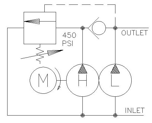
So, we don’t actually turn one of the pumps off. It is very difficult to mechanically disconnect the pump, but we do the next best thing. So earlier in the article I mentioned that pumps move oil they don’t create pressure. Keeping this in mind, we can simply recirculate the oil from the pressure side back to the tank side. Simple. So, let’s look at this as a schematic.
Luckily, turning off the pump is quite simple and only involves two components: a check valve and an unloader valve. The check valve is there to keep the higher-pressure oil from the low flow pump separate from the oil in the high flow pump. The higher-pressure oil from the low flow pump will shift the unloader valve by compressing the spring. This allows flow from the high flow pump to return to the suction line of the pump. Many pumps have this return line internal to the pump, so there is no additional plumbing needed. At this point, the high flow pump uses little to no power to perform this action. You will notice that the cylinder speed slows dramatically. As the log splits apart, the pressure may drop causing the unloader valve to close again. At this point, the flows will combine again. This process may repeat several times during a single split.
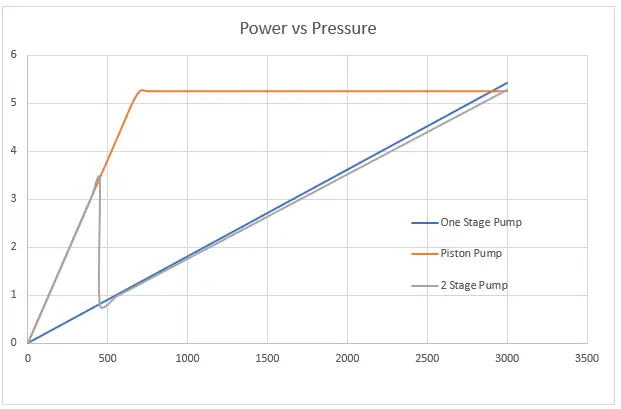
The graph above shows the overlay of a performance curve of a piston pump and two stage gear pumps. As you can see, the piston pump between 700 psi and 3000 psi will deliver the maximum HP that our engine can produce and as a result, it will have maximum speed. Unfortunately, it will also have maximum cost. If we are willing to sacrifice a little performance, the two-stage pump will work very well. Most of our work is done under 500 psi where the two pumps have identical performance. As pressure builds, the gear pump will be at a slight disadvantage, but with good performance. The amount of time we spend in this region of the curve is very little and it would be hard to calculate the time wasted.
After the pump on my log splitter died, I replaced it with a two-stage pump. While I was missing out on the full benefits of the piston pump, there was a tremendous increase in my output (logs/hr.). I noticed that instead of me waiting on the cylinder to be in the right position, I was now the hold up. I couldn’t get the logs in and positioned fast enough. What a difference!
As you go from a standard two-stage pump to your own custom design, you will find that you will need to add the check valve and unloader separately. However, there are many available cartridges manifold out there already that make this simple. Some even have relief valves built in!
Two stage pumps are wonderful creations! They allow for better utilization of pressure, flow and power by giving you two performance curve areas. They also show their versatility in conserving power which leads to energy savings while remaining inexpensive. A lot of these pumps come pre-made and preset, but you can make your own! See if your next project can get a boost from one of these wonderful devices.

http://www.energymfg.com/pdf/16445x.pdfGood catch, I should have seen that. Now the interesting part is that the relief is preset 2000psi from factory and a max range of 2500psi. His engine should pull that without any serious bogging. Rereading the first post, he says it boggs out and stalls. I am now wondering if its the engine that is stalling, ( which is what I thought he was saying),or the cylinder that is stalling. I think that issue needs to be clarified before going any further. If the cylinder is what is stalling, and the engine continues to run, it could just be a matter of the relief being set to low, or to small a cylinder for the wood being split. If it is indeed not shifting into lowflow/high pressure, then he might need to adjust the pump to the the 650psi high flow/ low pressure. Remove the cap on the inlet side of the pump. Under the cap is a slotted screw. Turn clockwise to increase pressure. Turn the screw all the way clockwise to the stop and see if the engine can handle it. If not then back it out a little and try again. Run the engine full throttle and plan to play with the setting until you find the limit for your engine. You will find that the higher you can run the pressure on high flow side, the less the pump will kick down into low flow/high pressure and the faster your splitter will work. If you engine is actually already what is bogging, you may have to turn the screw counter clockwise to lower the unloader pressure.. It is best to use a pressure gauge, but you can do this by ear. If its killing the engine, just turn the screw out until it no longer kills the engine. You should adjust the relief setting on the control valvle first before trying to adjust the unloader valve on the pump. The load is what will cause the pressure to build, you can simulate a full load by fully extending or retracting the cyl, and the relief valve on the valve will activate. If it will not get to 2500 psi, then the valve pressure relief (on control valve) is not set, or you don"t have a load equivalent to 2500 psi. With a gauge installed, pressure will be at a minimum until you activate the lever on the control valve, Once lever is activated, pressure should climb on the gauge until the cyl is fully extended or retracted, at which point the pressure will climb rapidly to the relief setting. Watch the gauge, it should jump from the settings on the pump unloader valve (650psi), to the setting on the relief (2500psi). You may need to split a round or two to actually see the pressure spike as the spike can be pretty fast
I will just add, that I have never had to adjust the relief on the control valve or unloader relief on a pump that was new out of the box. Usually if the reliefs need adjusting, its because someone has already been messing with them. Usually the factory guys have it pretty close, not saying mess ups dont happen, just that it is unusual when it does. I also usually use large bore cyls and bigger hp engines than the minimums required. If you have the hp to pull the pumps and cyls that create more than enough force, the factory relief setting will usually take care of themselfs.

Check that the pump shaft is rotating. Even though coupling guards and C-face mounts can make this difficult to confirm, it is important to establish if your pump shaft is rotating. If it isn’t, this could be an indication of a more severe issue, and this should be investigated immediately.
Check the oil level. This one tends to be the more obvious check, as it is often one of the only factors inspected before the pump is changed. The oil level should be three inches above the pump suction. Otherwise, a vortex can form in the reservoir, allowing air into the pump.
What does the pump sound like when it is operating normally? Vane pumps generally are quieter than piston and gear pumps. If the pump has a high-pitched whining sound, it most likely is cavitating. If it has a knocking sound, like marbles rattling around, then aeration is the likely cause.
Cavitation is the formation and collapse of air cavities in the liquid. When the pump cannot get the total volume of oil it needs, cavitation occurs. Hydraulic oil contains approximately nine percent dissolved air. When the pump does not receive adequate oil volume at its suction port, high vacuum pressure occurs.
This dissolved air is pulled out of the oil on the suction side and then collapses or implodes on the pressure side. The implosions produce a very steady, high-pitched sound. As the air bubbles collapse, the inside of the pump is damaged.
While cavitation is a devastating development, with proper preventative maintenance practices and a quality monitoring system, early detection and deterrence remain attainable goals. UE System’s UltraTrak 850S CD pump cavitation sensor is a Smart Analog Sensor designed and optimized to detect cavitation on pumps earlier by measuring the ultrasound produced as cavitation starts to develop early-onset bubbles in the pump. By continuously monitoring the impact caused by cavitation, the system provides a simple, single value to trend and alert when cavitation is occurring.
The oil viscosity is too high. Low oil temperature increases the oil viscosity, making it harder for the oil to reach the pump. Most hydraulic systems should not be started with the oil any colder than 40°F and should not be put under load until the oil is at least 70°F.
Many reservoirs do not have heaters, particularly in the South. Even when heaters are available, they are often disconnected. While the damage may not be immediate, if a pump is continually started up when the oil is too cold, the pump will fail prematurely.
The suction filter or strainer is contaminated. A strainer is typically 74 or 149 microns in size and is used to keep “large” particles out of the pump. The strainer may be located inside or outside the reservoir. Strainers located inside the reservoir are out of sight and out of mind. Many times, maintenance personnel are not even aware that there is a strainer in the reservoir.
The suction strainer should be removed from the line or reservoir and cleaned a minimum of once a year. Years ago, a plant sought out help to troubleshoot a system that had already had five pumps changed within a single week. Upon closer inspection, it was discovered that the breather cap was missing, allowing dirty air to flow directly into the reservoir.
A check of the hydraulic schematic showed a strainer in the suction line inside the tank. When the strainer was removed, a shop rag was found wrapped around the screen mesh. Apparently, someone had used the rag to plug the breather cap opening, and it had then fallen into the tank. Contamination can come from a variety of different sources, so it pays to be vigilant and responsible with our practices and reliability measures.
The electric motor is driving the hydraulic pump at a speed that is higher than the pump’s rating. All pumps have a recommended maximum drive speed. If the speed is too high, a higher volume of oil will be needed at the suction port.
Due to the size of the suction port, adequate oil cannot fill the suction cavity in the pump, resulting in cavitation. Although this rarely happens, some pumps are rated at a maximum drive speed of 1,200 revolutions per minute (RPM), while others have a maximum speed of 3,600 RPM. The drive speed should be checked any time a pump is replaced with a different brand or model.
Every one of these devastating causes of cavitation threatens to cause major, irreversible damage to your equipment. Therefore, it’s not only critical to have proper, proactive practices in place, but also a monitoring system that can continuously protect your valuable assets, such as UE System’s UltraTrak 850S CD pump cavitation senor. These sensors regularly monitor the health of your pumps and alert you immediately if cavitation symptoms are present, allowing you to take corrective action before it’s too late.
Aeration is sometimes known as pseudo cavitation because air is entering the pump suction cavity. However, the causes of aeration are entirely different than that of cavitation. While cavitation pulls air out of the oil, aeration is the result of outside air entering the pump’s suction line.
Several factors can cause aeration, including an air leak in the suction line. This could be in the form of a loose connection, a cracked line, or an improper fitting seal. One method of finding the leak is to squirt oil around the suction line fittings. The fluid will be momentarily drawn into the suction line, and the knocking sound inside the pump will stop for a short period of time once the airflow path is found.
A bad shaft seal can also cause aeration if the system is supplied by one or more fixed displacement pumps. Oil that bypasses inside a fixed displacement pump is ported back to the suction port. If the shaft seal is worn or damaged, air can flow through the seal and into the pump’s suction cavity.
As mentioned previously, if the oil level is too low, oil can enter the suction line and flow into the pump. Therefore, always check the oil level with all cylinders in the retracted position.
If a new pump is installed and pressure will not build, the shaft may be rotating in the wrong direction. Some gear pumps can be rotated in either direction, but most have an arrow on the housing indicating the direction of rotation, as depicted in Figure 2.
Pump rotation should always be viewed from the shaft end. If the pump is rotated in the wrong direction, adequate fluid will not fill the suction port due to the pump’s internal design.
A fixed displacement pump delivers a constant volume of oil for a given shaft speed. A relief valve must be included downstream of the pump to limit the maximum pressure in the system.
After the visual and sound checks are made, the next step is to determine whether you have a volume or pressure problem. If the pressure will not build to the desired level, isolate the pump and relief valve from the system. This can be done by closing a valve, plugging the line downstream, or blocking the relief valve. If the pressure builds when this is done, there is a component downstream of the isolation point that is bypassing. If the pressure does not build up, the pump or relief valve is bad.
If the system is operating at a slower speed, a volume problem exists. Pumps wear over time, which results in less oil being delivered. While a flow meter can be installed in the pump’s outlet line, this is not always practical, as the proper fittings and adapters may not be available. To determine if the pump is badly worn and bypassing, first check the current to the electric motor. If possible, this test should be made when the pump is new to establish a reference. Electric motor horsepower is relative to the hydraulic horsepower required by the system.
For example, if a 50-GPM pump is used and the maximum pressure is 1,500 psi, a 50-hp motor will be required. If the pump is delivering less oil than when it was new, the current to drive the pump will drop. A 230-volt, 50-hp motor has an average full load rating of 130 amps. If the amperage is considerably lower, the pump is most likely bypassing and should be changed.
Figure 4.To isolate a fixed displacement pump and relief valve from the system, close a valve or plug the line downstream (left). If pressure builds, a component downstream of the isolation point is bypassing (right).
The most common type of variable displacement pump is the pressure-compensating design. The compensator setting limits the maximum pressure at the pump’s outlet port. The pump should be isolated as described for the fixed displacement pump.
If pressure does not build up, the relief valve or pump compensator may be bad. Prior to checking either component, perform the necessary lockout procedures and verify that the pressure at the outlet port is zero psi. The relief valve and compensator can then be taken apart and checked for contamination, wear, and broken springs.
Install a flow meter in the case drain line and check the flow rate. Most variable displacement pumps bypass one to three percent of the maximum pump volume through the case drain line. If the flow rate reaches 10 percent, the pump should be changed. Permanently installing a flow meter in the case drain line is an excellent reliability and troubleshooting tool.
Ensure the compensator is 200 psi above the maximum load pressure. If set too low, the compensator spool will shift and start reducing the pump volume when the system is calling for maximum volume.
Performing these recommended tests should help you make good decisions about the condition of your pumps or the cause of pump failures. If you change a pump, have a reason for changing it. Don’t just do it because you have a spare one in stock.
Conduct a reliability assessment on each of your hydraulic systems so when an issue occurs, you will have current pressure and temperature readings to consult.
Al Smiley is the president of GPM Hydraulic Consulting Inc., located in Monroe, Georgia. Since 1994, GPM has provided hydraulic training, consulting and reliability assessments to companies in t...

Things like restrictions and blockages can impede the flow of fluid to your pump. which could contribute to poor fluid flow. Air leak in suction line. Air present in the pump at startup. Insufficient supply of oil in pump. Clogged or dirty fluid filters. Clogged inlet lines or hoses. Blocked reservoir breather vent. Low oil in the reservoir
Now that we’ve ensured that the directional control is not reversed, it’s time to check that the drive motor itself is turning in the right direction. Sometimes incorrect installation leads to mismatched pipe routings between control valves and motors, which can reverse the direction of flow. Check to see that the motor is turning the pump in the right direction and if not - look at your piping.
Check to ensure that your pump drive motor is turning over and is developing the required speed and torque. In some cases, misalignment can cause binding of the drive shaft, which can prevent the motor from turning. If this is the case, correct the misalignment and inspect the motor for damage. If required, overhaul or replace motor.
Check to ensure the pump to motor coupling is undamaged. A sheared pump coupling is an obvious cause of failure, however the location of some pumps within hydraulic systems makes this difficult to check so it may go overlooked
It is possible that the entire flow could be passing over the relief valve, preventing the pressure from developing. Check that the relief valve is adjusted properly for the pump specifications and the application.
Seized bearings, or pump shafts and other internal damage may prevent the pump from operating all together. If everything else checks out, uncouple the pump and motor and check to see that the pump shaft is able to turn. If not, overhaul or replace the pump.
If your pump is having problems developing sufficient power, following this checklist will help you to pinpoint the problem. In some cases you may find a simple solution is the answer. If your pump is exhibiting any other issues such as noise problems, heat problems or flow problems, you may need to do some more investigation to address the root cause of your pump problem. To help, we’ve created a downloadable troubleshooting guide containing more information about each of these issues. So that you can keep your system up and running and avoid unplanned downtime. Download it here.

Check that the pump shaft is rotating. Even though coupling guards and C-face mounts can make this difficult to confirm, it is important to establish if your pump shaft is rotating. If it isn’t, this could be an indication of a more severe issue, and this should be investigated immediately.
Check the oil level. This one tends to be the more obvious check, as it is often one of the only factors inspected before the pump is changed. The oil level should be three inches above the pump suction. Otherwise, a vortex can form in the reservoir, allowing air into the pump.
What does the pump sound like when it is operating normally? Vane pumps generally are quieter than piston and gear pumps. If the pump has a high-pitched whining sound, it most likely is cavitating. If it has a knocking sound, like marbles rattling around, then aeration is the likely cause.
Cavitation is the formation and collapse of air cavities in the liquid. When the pump cannot get the total volume of oil it needs, cavitation occurs. Hydraulic oil contains approximately nine percent dissolved air. When the pump does not receive adequate oil volume at its suction port, high vacuum pressure occurs.
This dissolved air is pulled out of the oil on the suction side and then collapses or implodes on the pressure side. The implosions produce a very steady, high-pitched sound. As the air bubbles collapse, the inside of the pump is damaged.
While cavitation is a devastating development, with proper preventative maintenance practices and a quality monitoring system, early detection and deterrence remain attainable goals. UE System’s UltraTrak 850S CD pump cavitation sensor is a Smart Analog Sensor designed and optimized to detect cavitation on pumps earlier by measuring the ultrasound produced as cavitation starts to develop early-onset bubbles in the pump. By continuously monitoring the impact caused by cavitation, the system provides a simple, single value to trend and alert when cavitation is occurring.
The oil viscosity is too high. Low oil temperature increases the oil viscosity, making it harder for the oil to reach the pump. Most hydraulic systems should not be started with the oil any colder than 40°F and should not be put under load until the oil is at least 70°F.
Many reservoirs do not have heaters, particularly in the South. Even when heaters are available, they are often disconnected. While the damage may not be immediate, if a pump is continually started up when the oil is too cold, the pump will fail prematurely.
The suction filter or strainer is contaminated. A strainer is typically 74 or 149 microns in size and is used to keep “large” particles out of the pump. The strainer may be located inside or outside the reservoir. Strainers located inside the reservoir are out of sight and out of mind. Many times, maintenance personnel are not even aware that there is a strainer in the reservoir.
The suction strainer should be removed from the line or reservoir and cleaned a minimum of once a year. Years ago, a plant sought out help to troubleshoot a system that had already had five pumps changed within a single week. Upon closer inspection, it was discovered that the breather cap was missing, allowing dirty air to flow directly into the reservoir.
A check of the hydraulic schematic showed a strainer in the suction line inside the tank. When the strainer was removed, a shop rag was found wrapped around the screen mesh. Apparently, someone had used the rag to plug the breather cap opening, and it had then fallen into the tank. Contamination can come from a variety of different sources, so it pays to be vigilant and responsible with our practices and reliability measures.
The electric motor is driving the hydraulic pump at a speed that is higher than the pump’s rating. All pumps have a recommended maximum drive speed. If the speed is too high, a higher volume of oil will be needed at the suction port.
Due to the size of the suction port, adequate oil cannot fill the suction cavity in the pump, resulting in cavitation. Although this rarely happens, some pumps are rated at a maximum drive speed of 1,200 revolutions per minute (RPM), while others have a maximum speed of 3,600 RPM. The drive speed should be checked any time a pump is replaced with a different brand or model.
Every one of these devastating causes of cavitation threatens to cause major, irreversible damage to your equipment. Therefore, it’s not only critical to have proper, proactive practices in place, but also a monitoring system that can continuously protect your valuable assets, such as UE System’s UltraTrak 850S CD pump cavitation senor. These sensors regularly monitor the health of your pumps and alert you immediately if cavitation symptoms are present, allowing you to take corrective action before it’s too late.
Aeration is sometimes known as pseudo cavitation because air is entering the pump suction cavity. However, the causes of aeration are entirely different than that of cavitation. While cavitation pulls air out of the oil, aeration is the result of outside air entering the pump’s suction line.
Several factors can cause aeration, including an air leak in the suction line. This could be in the form of a loose connection, a cracked line, or an improper fitting seal. One method of finding the leak is to squirt oil around the suction line fittings. The fluid will be momentarily drawn into the suction line, and the knocking sound inside the pump will stop for a short period of time once the airflow path is found.
A bad shaft seal can also cause aeration if the system is supplied by one or more fixed displacement pumps. Oil that bypasses inside a fixed displacement pump is ported back to the suction port. If the shaft seal is worn or damaged, air can flow through the seal and into the pump’s suction cavity.
As mentioned previously, if the oil level is too low, oil can enter the suction line and flow into the pump. Therefore, always check the oil level with all cylinders in the retracted position.
If a new pump is installed and pressure will not build, the shaft may be rotating in the wrong direction. Some gear pumps can be rotated in either direction, but most have an arrow on the housing indicating the direction of rotation, as depicted in Figure 2.
Pump rotation should always be viewed from the shaft end. If the pump is rotated in the wrong direction, adequate fluid will not fill the suction port due to the pump’s internal design.
A fixed displacement pump delivers a constant volume of oil for a given shaft speed. A relief valve must be included downstream of the pump to limit the maximum pressure in the system.
After the visual and sound checks are made, the next step is to determine whether you have a volume or pressure problem. If the pressure will not build to the desired level, isolate the pump and relief valve from the system. This can be done by closing a valve, plugging the line downstream, or blocking the relief valve. If the pressure builds when this is done, there is a component downstream of the isolation point that is bypassing. If the pressure does not build up, the pump or relief valve is bad.
If the system is operating at a slower speed, a volume problem exists. Pumps wear over time, which results in less oil being delivered. While a flow meter can be installed in the pump’s outlet line, this is not always practical, as the proper fittings and adapters may not be available. To determine if the pump is badly worn and bypassing, first check the current to the electric motor. If possible, this test should be made when the pump is new to establish a reference. Electric motor horsepower is relative to the hydraulic horsepower required by the system.
For example, if a 50-GPM pump is used and the maximum pressure is 1,500 psi, a 50-hp motor will be required. If the pump is delivering less oil than when it was new, the current to drive the pump will drop. A 230-volt, 50-hp motor has an average full load rating of 130 amps. If the amperage is considerably lower, the pump is most likely bypassing and should be changed.
Figure 4.To isolate a fixed displacement pump and relief valve from the system, close a valve or plug the line downstream (left). If pressure builds, a component downstream of the isolation point is bypassing (right).
The most common type of variable displacement pump is the pressure-compensating design. The compensator setting limits the maximum pressure at the pump’s outlet port. The pump should be isolated as described for the fixed displacement pump.
If pressure does not build up, the relief valve or pump compensator may be bad. Prior to checking either component, perform the necessary lockout procedures and verify that the pressure at the outlet port is zero psi. The relief valve and compensator can then be taken apart and checked for contamination, wear, and broken springs.
Install a flow meter in the case drain line and check the flow rate. Most variable displacement pumps bypass one to three percent of the maximum pump volume through the case drain line. If the flow rate reaches 10 percent, the pump should be changed. Permanently installing a flow meter in the case drain line is an excellent reliability and troubleshooting tool.
Ensure the compensator is 200 psi above the maximum load pressure. If set too low, the compensator spool will shift and start reducing the pump volume when the system is calling for maximum volume.
Performing these recommended tests should help you make good decisions about the condition of your pumps or the cause of pump failures. If you change a pump, have a reason for changing it. Don’t just do it because you have a spare one in stock.
Conduct a reliability assessment on each of your hydraulic systems so when an issue occurs, you will have current pressure and temperature readings to consult.
Al Smiley is the president of GPM Hydraulic Consulting Inc., located in Monroe, Georgia. Since 1994, GPM has provided hydraulic training, consulting and reliability assessments to companies in t...

Variable-displacement pumps are used in hydraulic systems where the flow requirements vary. This usually means the system has several actuators and, depending on the current cycle of the machine, the number of actuators moving at a given time will fluctuate. The most common type of variable-displacement pump is the pressure-compensating pump.
Pressure-compensating pumps are designed to deliver only the amount of flow required by the system to maximize efficiency and avoid heat generation. The compensator is adjusted to a pressure somewhat higher than that required to move the system’s heaviest load.
A pressure-compensating pump will deliver its maximum flow until the system pressure reaches the compensator setting. Once the compensator setting is reached, the pump will be de-stroked to deliver only the amount of flow that will maintain the compensator setting in the line.
Whenever more flow is demanded by the system (such as would occur when an additional actuator begins to move), the pump will increase its stroke to meet the new flow demand. Whenever the system flow needs to decrease (such as when one or more actuators are stopped), the pump stroke is reduced.
When the system is stopped completely, the pump stroke is reduced almost to zero. It will stroke only a very small amount or whatever is required to maintain the compensator setting in the line, overcoming any system bypassing or leaks. While a pressure-compensating pump is efficient, the standby pressure remains high.
Adjusting a pressure-compensating pump is quite simple. With all flow blocked and the system idle, the compensator valve is adjusted to the desired pressure. However, some pressure-compensating pumps have two valves mounted on the pump body.
The two adjustments can look nearly identical. This type of pressure-compensating pump is called a load-sensing pump. The second adjustment is called either a “load-sensing” valve or “flow-compensator” valve.
A load-sensing pump is designed to reduce its pressure to a much lower standby level whenever the system is idle. This can conserve energy and reduce heat and wear in systems that spend a significant amount of time in an idle condition.
The two separate pressure adjustments allow setting the compensator valve to the required maximum system pressure and the load-sensing adjustment to a much lower standby pressure.
Whenever the system is moving a load, the high-pressure adjustment limits the system pressure. For instance, as a cylinder is extended, pressure in the system will build as necessary to move the load. Eventually, the cylinder reaches the end of its stroke, and flow is blocked.
Most load-sensing systems have a pump-loading directional-control valve of some sort that can place the system in an idle condition until it is necessary to move another load. When the pump-loading valve is shifted, the system pressure drops to the much lower load-sensing valve setting.
A load-sensing valve usually is smaller than the compensator valve and typically mounted directly on top of the compensator. The compensator valve is closer to the pump. The load-sensing valve is factory preset and normally does not need to be adjusted during the initial pump setup. In most pumps, the factory preset is approximately 200-300 pounds per square inch (psi).
The most common reason to adjust a load-sensing valve is because someone unfamiliar with the pump has mistakenly attempted to set the maximum system pressure by adjusting the load-sensing valve instead of the compensator. This not only can result in unstable system pressure but in some cases can also void any warranty on the pump.
A typical configuration of a pressure-compensating pump is shown in Figure 1. A pump-loading valve is used to determine whether the system is idle or prepared to move a load. The pump-loading valve is de-energized whenever the system is idle.
Pilot pressure on the left-hand side of the load-sensing valve is then released to the tank. The pilot line on the right-hand side of the load-sensing valve is connected to the pressure line at the pump outlet. System pressure shifts the load-sensing valve and directs pressure to reduce the pump stroke so that system pressure drops to the load-sensing setting of 300 psi, as illustrated in Figure 2.
When a load is to be moved, the pump-loading valve is energized. This directs pilot pressure to the left side of the load-sensing valve, keeping it from shifting. System pressure shifts the compensator valve to de-stroke the pump exactly the amount necessary to limit system pressure to the compensator setting, 3,000 psi as shown in Figure 3.
To make the pressure settings, always adjust the load-sensing valve first. The pump should be deadheaded by closing the manual hand valve. With the pump-loading valve de-energized, pressure will build only to the current setting of the load-sensing valve. Adjust the load-sensing valve to the desired pressure.
Once the load-sensing valve is set, energize the pump-loading valve. System pressure will then build to the current compensator setting. Adjust the compensator to the desired setting. Open the manual valve, and the system can be placed back into service.
Jack Weeks is a hydraulic instructor and consultant for GPM Hydraulic Consulting. Since 1997 he has trained thousands of electricians and mechanics in hydraulic troubleshooting methods. Jack has...
In waterworks and wastewater systems, pumps are commonly installed at the source to raise the water level and at intermediate points to boost the water pressure. The components and design of a pumping station are vital to its effectiveness. Centrifugal pumps are most often used in water and wastewater systems, making it important to learn how they work and how to design them. Centrifugal pumps have several advantages over other types of pumps, including:
A centrifugal pump consists of a rotating shaft that is connected to an impeller, which is usually comprised of curved blades. The impeller rotates within its casing and sucks the fluid through the eye of the casing (point 1 in Figure 10.1). The fluid’s kinetic energy increases due to the energy added by the impeller and enters the discharge end of the casing that has an expanding area (point 2 in Figure 10.1). The pressure within the fluid increases accordingly.
The characteristic curves of commercial pumps are provided by manufacturers. Otherwise, a pump should be tested in the laboratory, under various discharge and head conditions, to produce such curves. If a single pump is incapable of delivering the design flow rate and pressure, additional pumps, in series or parallel with the original pump, can be considered. The characteristic curves of pumps in series or parallel should be constructed since this information helps engineers select the types of pumps needed and how they should be configured.
Many pumps are in use around the world to handle liquids, gases, or liquid-solid mixtures. There are pumps in cars, swimming pools, boats, water treatment facilities, water wells, etc. Centrifugal pumps are commonly used in water, sewage, petroleum, and petrochemical pumping. It is important to select the pump that will best serve the project’s needs.
The objective of this experiment is to determine the operational characteristics of two centrifugal pumps when they are configured as a single pump, two pumps in series, and two pumps in parallel.
Each configuration (single pump, two pumps in series, and two pumps in parallel) will be tested at pump speeds of 60, 70, and 80 rev/sec. For each speed, the bench regulating valve will be set to fully closed, 25%, 50%, 75%, and 100% open. Timed water collections will be performed to determine flow rates for each test, and the head, hydraulic power, and overall efficiency ratings will be obtained.
The hydraulics bench is fitted with a single centrifugal pump that is driven by a single-phase A.C. motor and controlled by a speed control unit. An auxiliary pump and the speed control unit are supplied to enhance the output of the bench so that experiments can be conducted with the pumps connected either in series or in parallel. Pressure gauges are installed at the inlet and outlet of the pumps to measure the pressure head before and after each pump. A watt-meter unit is used to measure the pumps’ input electrical power [10].
Consider the pump shown in Figure 10.3. The work done by the pump, per unit mass of fluid, will result in increases in the pressure head, velocity head, and potential head of the fluid between points 1 and 2. Therefore:
While pumping fluid, the pump has to overcome the pressure loss that is caused by friction in any valves, pipes, and fittings in the pipe system. This frictional head loss is approximately proportional to the square of the flow rate. The total system head that the pump has to overcome is the sum of the total static head and the frictional head. The total static head is the sum of the static suction lift and the static discharge head, which is equal to the difference between the water levels of the discharge and the source tank (Figure 10.4). A plot of the total head-discharge for a pipe system is called asystem curve; it is superimposed onto a pump characteristic curve in Figure 10.5. The operating point for the pump-pipe system combination occurs where the two graphs intercept [10].
Pumps are used in series in a system where substantial head changes take place without any appreciable difference in discharge. When two or more pumps are configured in series, the flow rate throughout the pumps remains the same; however, each pump contributes to the increase in the head so that the overall head is equal to the sum of the contributions of each pump [10]. For n pumps in series:
The composite characteristic curve of pumps in series can be prepared by adding the ordinates (heads) of all of the pumps for the same values of discharge. The intersection point of the composite head characteristic curve and the system curve provides the operating conditions (performance point) of the pumps (Figure 10.6).
Parallel pumps are useful for systems with considerable discharge variations and with no appreciable head change. In parallel, each pump has the same head. However, each pump contributes to the discharge so that the total discharge is equal to the sum of the contributions of each pump [10]. Thus for pumps:
The composite head characteristic curve is obtained by summing up the discharge of all pumps for the same values of head. A typical pipe system curve and performance point of the pumps are shown in Figure 10.7.
d) Record the pump 1 inlet pressure (P1) and outlet pressure (P2). Record the input power from the watt-meter (Wi). (With the regulating valve fully closed, discharge will be zero.)
d) Record the pump 1 and 2 inlet pressure (P1) and outlet pressure (P2). Record the input power for pump 1 from the wattmeter (Wi). (With the regulating valve fully closed, discharge will be zero.)
Correct the pressure rise measurement (outlet pressure) across the pump by adding a 0.07 bar to allow for the difference of 0.714 m in height between the measurement point for the pump outlet pressure and the actual pump outlet connection.
In each of above graphs, show the results for single pump, two pumps in series, and two pumps in parallel – a total of three graphs. Do not connect the experimental data points, and use best fit to plot the graphs
For using the ITH-High pressure Hand lever pumps Lever-MAX there is no external power supply needed and no pneumatic air pressure is needed. A distinction is made between the single-stage Lever-MAX and the double-stage Lever-MAX. Both designs are built for service jobs and provide a compact design, easy transport, and fast handling.
ITH offers the double-stage version to perform faster bolting procedures. The Mini version allows a shorter oil tank (less usable oil) therefore it is lighter. Also two-stage manual hydraulic pumps are optionally available.
Manual operating - ideal for service jobscompact design, double-stage development for fastest bolting proceduresno electric or air power supply necessarysecond high pressure coupling optional
To perform faster bolting procedures ITH offers a doublestage manual pump series. Use Lever-MAX 255 with highest flowrate per stroke for more faster and more efficient bolting procedures.Model versionsup to 3.000 bar:Lever-MAX Double Stage 235

If you’re a pump sprayer operator and you’re performing a soft wash application on a two-story residential home to remove lichen or mold, how do you get the spray pattern to reach the eaves of the home and provide even coverage without having to climb a ladder?
There’s a common misconception that to achieve a broader vertical or horizontal spray pattern, you simply need a pump that puts out more pressure. On the contrary, increasing the flow rate is often the key.
It’s not uncommon to hear pump operators complain that their sprayer doesn’t have enough pressure when, in fact, the issue is the flow rate. In fact, some people use the two terms interchangeably, as though they’re the same thing. They’re not, and knowing the difference and the role each plays is the key to achieving proper pump performance.
A pump’s job is not to deliver pressure; rather, it is to deliver a rate of flow, pumping a certain amount of liquid over a given amount of time from a tank or reservoir to the outlet. Flow rates are often referred to in gallons per minute or GPM. There are some smaller pumps that rate flow at gallons per hour or even gallons per day, outputting extremely small amounts of fluid over a given time.
Pump pressure, however, is a measure of resistance to flow. Without flow, there is no pressure. In a positive displacement pump, such as a plunger pump, the rating in pounds per square inch, or PSI, outlines how much resistance the pump is designed to withstand.
A pump’s PSI rating is important because it indicates that the pump was manufactured out of materials and designed to handle a certain amount of pressure. But for pump operators, they should be equally concerned with a pump’s flow rate which determines how much you want to dispense, spray, or inject.
In general, when pump pressure increases, flow will decrease. Take, for example, a misting pump that needs to produce an ultra-fine mist for cooling or dust suppression. Many misting pumps are rated at 1,000 PSI, yet their flow rate is quite low at .25 GPM.
More pressure changes the velocity of the fluid, but it also decreases the flow or output. The cause of the flow decrease is due to two factors: volumetric efficiency of the pump and reduced motor speed. Volumetric efficiency is a measure of the actual flow compared to expected theoretical (calculated) flow — volumetric efficiency decreases as pressure increases. Our positive displacement plunger pumps have about 90–100% volumetric efficiency compared to centrifugal pumps that range from 0–100%. This means that plunger pumps only lose about 10% of the flow when pumping against back-pressure, while centrifugal pumps will lose all the flow when pressure climbs too high.
Reduced motor speed occurs when motors are loaded heavier. So, when pressure in the pump causes more load on the motor, it slows down. When the motor slows down, the flow rate drops at the same percentage. A motor that operates at about 2000 RPM at low pressures will typically slow down to about 1750 RPM when the pump is pressurized to the maximum rating.
It stands to reason, then, that increasing pump pressure will not increase flow. In the soft wash example, more pressure won’t help the operator reach the eaves of a two-story home with the same amount of coverage. The operator needs a pump motor with an ideal combination of pressure and flow.
Engineering pumps for any application requires an understanding of fluid dynamics, and each industry has varying needs. Too often, a company will choose an off-the-shelf high-pressure pump to get a job done and wonder why it doesn’t perform as expected. It’s likely because the operators lack a full understanding of the relationship between flow and pressure.
The engineering experts at Pumptec have a thorough grasp on fluid dynamics and help OEMs and pump distributors pinpoint their exact needs. They make recommendations based on scientific principles and years of experience serving multiple industries, and can even customize pumps to your application’s precise needs.
In fact, we’ve developed a Guide to GPM and PSI that provides some of those industry recommendations. Take a look through it and then contact the pump experts at Pumptec. We’ll be happy to discuss your needs and determine the right pump for your application.


 8613371530291