
two stage hydraulic pump adjustment quotation
http://www.energymfg.com/pdf/16445x.pdfGood catch, I should have seen that. Now the interesting part is that the relief is preset 2000psi from factory and a max range of 2500psi. His engine should pull that without any serious bogging. Rereading the first post, he says it boggs out and stalls. I am now wondering if its the engine that is stalling, ( which is what I thought he was saying),or the cylinder that is stalling. I think that issue needs to be clarified before going any further. If the cylinder is what is stalling, and the engine continues to run, it could just be a matter of the relief being set to low, or to small a cylinder for the wood being split. If it is indeed not shifting into lowflow/high pressure, then he might need to adjust the pump to the the 650psi high flow/ low pressure. Remove the cap on the inlet side of the pump. Under the cap is a slotted screw. Turn clockwise to increase pressure. Turn the screw all the way clockwise to the stop and see if the engine can handle it. If not then back it out a little and try again. Run the engine full throttle and plan to play with the setting until you find the limit for your engine. You will find that the higher you can run the pressure on high flow side, the less the pump will kick down into low flow/high pressure and the faster your splitter will work. If you engine is actually already what is bogging, you may have to turn the screw counter clockwise to lower the unloader pressure.. It is best to use a pressure gauge, but you can do this by ear. If its killing the engine, just turn the screw out until it no longer kills the engine. You should adjust the relief setting on the control valvle first before trying to adjust the unloader valve on the pump. The load is what will cause the pressure to build, you can simulate a full load by fully extending or retracting the cyl, and the relief valve on the valve will activate. If it will not get to 2500 psi, then the valve pressure relief (on control valve) is not set, or you don"t have a load equivalent to 2500 psi. With a gauge installed, pressure will be at a minimum until you activate the lever on the control valve, Once lever is activated, pressure should climb on the gauge until the cyl is fully extended or retracted, at which point the pressure will climb rapidly to the relief setting. Watch the gauge, it should jump from the settings on the pump unloader valve (650psi), to the setting on the relief (2500psi). You may need to split a round or two to actually see the pressure spike as the spike can be pretty fast
I will just add, that I have never had to adjust the relief on the control valve or unloader relief on a pump that was new out of the box. Usually if the reliefs need adjusting, its because someone has already been messing with them. Usually the factory guys have it pretty close, not saying mess ups dont happen, just that it is unusual when it does. I also usually use large bore cyls and bigger hp engines than the minimums required. If you have the hp to pull the pumps and cyls that create more than enough force, the factory relief setting will usually take care of themselfs.

I"m referring to the type of hydraulic pump typically used on log splitters. It provides a high flow at lower pressure (to move the splitter wedge without resistance quickly) and a lower flow at high pressure (to move the wedge slower but with more force when resistance is encountered). How do these work internally to get the two different flows and pressures? Anybody know? It must be pretty simple, or it wouldn"t be reliable (right?).
I have a small tractor/loader whose "transmission" is a hydrostatic drive pump and 4 hydraulic wheel motors. One of the disadvantages of this design is that you only have 1 "gear"...slow! The thought struck me that some sort of two stage pump might give you more speed when there"s little resistance and more torque when it"s needed...kind of like a automagic gear-selector... /forums/images/graemlins/shocked.gif Any thoughts?

Push Button Stop/ Start, Lever Valve Action - Control lever forward: Pump into hose A, Returns to reservoir on hose B. Control lever neutral: Returns to reservoir on hose A and B. Control lever backward: Pump into hose B, Returns to reservoir on h

They"re called “RamRunners” and that"s just what they do…run large single- or double-acting rams for fast frame straightening, wheel alignment, etc. They deliver up to 45 cu. in./min. at max. operating pressure of 10,000 PSI. The 4044 has a 2-position/2-way valve with “advance” and “return” positions and is for use with single-acting rams. The 4046 and 4057 have a 3-position/4-way valve with advance,” “hold,” and “return” positions; for use with double-acting or multiple single-acting rams. Nos. 4044 and 4046 are equipped with a 1/2 h.p. single-phase, 60 Hz, 115 volt thermal protected electric motor and are designed to start under load. No. 4057 has a 1-1/2 h.p. electric motor. The RamRunners also feature a 6 ft. remote control cord for “on/off” control. One gallon and two quarts of oil are supplied.
No. 4046 –RamRunner two-stage hydraulic pump with3-position/4-way manual valve for double-acting rams,and a 6 ft. remote control cord. Supplied with onegallon and two quarts of oil. Wt., 54 lbs.
They"re called “RamRunners” and that"s just what they do…run large single- or double-acting rams for fast frame straightening, wheel alignment, etc. They deliver up to 45 cu. in./min. at max. operating pressure of 10,000 PSI. The 4044 has a 2-position/2-way valve with “advance” and “return” positions and is for use with single-acting rams. The 4046 and 4057 have a 3-position/4-way valve with advance,” “hold,” and “return” positions; for use with double-acting or multiple single-acting rams. Nos. 4044 and 4046 are equipped with a 1/2 h.p. single-phase, 60 Hz, 115 volt thermal protected electric motor and are designed to start under load. No. 4057 has a 1-1/2 h.p. electric motor. The RamRunners also feature a 6 ft. remote control cord for “on/off” control. One gallon and two quarts of oil are supplied.
No. 4044 – RamRunner two-stage hyd. pump with 2-position/2-way manual valve and a 6 ft. remote control cord. Supplied with one gallon and two quarts of oil. Wt., 58 lbs.

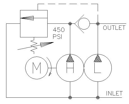
Model GP-CBN is a HI/LO hydraulic gear pump offers maximum pressures of 900 psi for the low pressure pump and 3000 psi for the high pressure pump. The change from LO to HI pressure is automatic with the LO pressure preset from 400 psi to 900 psi. The HI/LO pump is all cast iron. Applications for HI/LO Pump include log splitters, presses, etc. where rapid movement of the cylinder at low pressure is required prior to automatically switching to the high pressure mode to meet load requirements.

The pump is outfitted with a pressure relief valve. To increase the pump’s output pressure, turn the valve’s screw set in a clockwise direction. To decrease the pump’s pressure, turn the screw in a counterclockwise direction.
While the door’s head is in the open position, move the locking ring’s handle so the ring moves in the lock direction. The pump’s pressure gauge will denote the adjusted lock handle’s pressure once the locking ring’s rams get to their full motion.
This doesn’t require any adjustment. It is usually whatever the pump’s pressure is set at. However, some systems will have a pressure relief valve for adjusting this pressure. If yours does, refer to your manufacturer’s manual for the proper setting.
The steps to adjust your autoclave door’s hydraulic pump pressure settings must be followed to the letter to prevent a dangerous situation for you, other employees, and your equipment.

Hydraulic hand pumps play an essential role in every industry that requires the testing and calibrating of pressure instruments such as pressure transmitters, gauges, and switches. From energy production and health care to construction and wastewater management, they perform a very necessary function that ultimately helps keep our global economy running safely and efficiently.
With such a wide range of uses, there’s no single hand pump that serves the needs of every application. In this article, we’ll take a look at the basic functionality of hydraulic hand pumps and outline some of their most important characteristics.
Hand-operated hydraulic pumps convert mechanical energy into hydraulic energy (a combination of pressure and flow) by delivering hydraulic fluid under pressure through directly applied manual effort. They use the simple principle of a handle providing leverage to an internal piston. The piston then forces hydraulic fluid into the cylinder port. Water and hydraulic oil are the most common fluids, but a variety of pressure media may be used. The hydraulic energy generated is used to supply pressure for testing, adjusting, and calibrating different types of measuring instruments. This differs from pneumatic hand pumps, which generate pressure using air, a very compressible gas, rather than an incompressible fluid medium.
Hydraulic pressure test pumps are ideal for applications where a high level of pressure (10,000 psi or 70 MPa) is required. They’re typically used with a digital pressure calibrator to calibrate pressure transmitters and pressure gauges and in pressure switch testing and leak testing. Because they are lightweight and don’t require a power source, hand-operated hydraulic pumps are ideal in field testing situations where electric power or compressed gas sources are unavailable or unsuitable. They are especially well suited to hazardous locations in the oil and gas industry where electrically powered equipment is very expensive.
Hydraulic hand pumps have come a long way since their humble beginnings. Today, there are a variety of styles and pressure ranges available, and they are all generally engineered to be rugged, lightweight and easy to use. But there are a few essential characteristics of the hydraulic hand pump that are worth highlighting, particularly in comparison to their pneumatic equivalents.
Efficiency - Hydraulic pressure is one of the most efficient methods of transferring energy. A hydraulic hand pump allows you to reach high levels of pressure with very little effort - just one or two squeezes of the handle. Because air is compressible, it would take a much higher degree of effort to reach the same levels of pressure with a pneumatic pump.
Precision - Hand-operated hydraulic pumps are ideal in situations where a high degree of fine-tuning is required. They’re typically engineered with fine adjustment knobs that allow the operator to vary applied pressure to within .01 psi or .069 kPa.
Stability - Hydraulic hand pumps are typically made with either cast or machined metal to limit leaks, prevent maintenance and ensure temperature and pressure stability.
Overall, hydraulic hand pumps are designed to increase your operational efficiency. They are available in a wide range of pump styles and flow rates with varying pressure options tailored to different applications.
If you’re involved in the energy, oil and natural gas industries and regularly perform pressure calibration testing on instruments, Ralston Instruments offers two Hydraulic Hand Pump models that are definitely worth a look. Oilfields can be particularly rough on hand pumps, but the rugged design of the QTHP 5000 psi / 35 MPa and XTHP 10,000 psi / 70 MPa ensures the same level of efficiency, precision, and stability that make hydraulic hand pumps such an excellent choice, both in the field and off. We also offer EPDM seals which are necessary for calibrating Skydrol in the aviation industry and not commonly offered with similar hydraulic gauges.
For questions about hydraulic hand pumps or any of our pressure calibration products, give us a call at 800.347.6575, contact us or get a quote today!

Ultima Steel Hand Pumps are durable, portable, and highly efficient. Each model in the series features an all-steel construction, a chrome plated plunger, and a wiper system for long-lasting performance.
All except the P39 are 2 stage pumps, which reduces the number of handle strokes by as much as 78% compared to a single speed pump. This is ideal for applications when high flow is needed at the first stage, (such as when advancing a cylinder to the point of load contact). The pump switches automatically to the second stage which is the low flow high-pressure stage.
With a choice of oil capacities up to 453 in3 (7423 cm3), you will find Ultima Steel Hand Pumps that can handle multiple cylinder hook-ups, including models to suit either single-acting and double-acting cylinders.

Hydraulic pumps are mechanisms in hydraulic systems that move hydraulic fluid from point to point initiating the production of hydraulic power. Hydraulic pumps are sometimes incorrectly referred to as “hydrolic” pumps.
They are an important device overall in the hydraulics field, a special kind of power transmission which controls the energy which moving fluids transmit while under pressure and change into mechanical energy. Other kinds of pumps utilized to transmit hydraulic fluids could also be referred to as hydraulic pumps. There is a wide range of contexts in which hydraulic systems are applied, hence they are very important in many commercial, industrial, and consumer utilities.
“Power transmission” alludes to the complete procedure of technologically changing energy into a beneficial form for practical applications. Mechanical power, electrical power, and fluid power are the three major branches that make up the power transmission field. Fluid power covers the usage of moving gas and moving fluids for the transmission of power. Hydraulics are then considered as a sub category of fluid power that focuses on fluid use in opposition to gas use. The other fluid power field is known as pneumatics and it’s focused on the storage and release of energy with compressed gas.
"Pascal"s Law" applies to confined liquids. Thus, in order for liquids to act hydraulically, they must be contained within a system. A hydraulic power pack or hydraulic power unit is a confined mechanical system that utilizes liquid hydraulically. Despite the fact that specific operating systems vary, all hydraulic power units share the same basic components. A reservoir, valves, a piping/tubing system, a pump, and actuators are examples of these components. Similarly, despite their versatility and adaptability, these mechanisms work together in related operating processes at the heart of all hydraulic power packs.
The hydraulic reservoir"s function is to hold a volume of liquid, transfer heat from the system, permit solid pollutants to settle, and aid in releasing moisture and air from the liquid.
Mechanical energy is changed to hydraulic energy by the hydraulic pump. This is accomplished through the movement of liquid, which serves as the transmission medium. All hydraulic pumps operate on the same basic principle of dispensing fluid volume against a resistive load or pressure.
Hydraulic valves are utilized to start, stop, and direct liquid flow in a system. Hydraulic valves are made of spools or poppets and can be actuated hydraulically, pneumatically, manually, electrically, or mechanically.
The end result of Pascal"s law is hydraulic actuators. This is the point at which hydraulic energy is transformed back to mechanical energy. This can be accomplished by using a hydraulic cylinder to transform hydraulic energy into linear movement and work or a hydraulic motor to transform hydraulic energy into rotational motion and work. Hydraulic motors and hydraulic cylinders, like hydraulic pumps, have various subtypes, each meant for specific design use.
The essence of hydraulics can be found in a fundamental physical fact: fluids are incompressible. (As a result, fluids more closely resemble solids than compressible gasses) The incompressible essence of fluid allows it to transfer force and speed very efficiently. This fact is summed up by a variant of "Pascal"s Principle," which states that virtually all pressure enforced on any part of a fluid is transferred to every other part of the fluid. This scientific principle states, in other words, that pressure applied to a fluid transmits equally in all directions.
Furthermore, the force transferred through a fluid has the ability to multiply as it moves. In a slightly more abstract sense, because fluids are incompressible, pressurized fluids should keep a consistent pressure just as they move. Pressure is defined mathematically as a force acting per particular area unit (P = F/A). A simplified version of this equation shows that force is the product of area and pressure (F = P x A). Thus, by varying the size or area of various parts inside a hydraulic system, the force acting inside the pump can be adjusted accordingly (to either greater or lesser). The need for pressure to remain constant is what causes force and area to mirror each other (on the basis of either shrinking or growing). A hydraulic system with a piston five times larger than a second piston can demonstrate this force-area relationship. When a force (e.g., 50lbs) is exerted on the smaller piston, it is multiplied by five (e.g., 250 lbs) and transmitted to the larger piston via the hydraulic system.
Hydraulics is built on fluids’ chemical properties and the physical relationship between pressure, area, and force. Overall, hydraulic applications allow human operators to generate and exert immense mechanical force with little to no physical effort. Within hydraulic systems, both oil and water are used to transmit power. The use of oil, on the other hand, is far more common, owing in part to its extremely incompressible nature.
Pressure relief valves prevent excess pressure by regulating the actuators’ output and redirecting liquid back to the reservoir when necessary. Directional control valves are used to change the size and direction of hydraulic fluid flow.
While hydraulic power transmission is remarkably useful in a wide range of professional applications, relying solely on one type of power transmission is generally unwise. On the contrary, the most efficient strategy is to combine a wide range of power transmissions (pneumatic, hydraulic, mechanical, and electrical). As a result, hydraulic systems must be carefully embedded into an overall power transmission strategy for the specific commercial application. It is necessary to invest in locating trustworthy and skilled hydraulic manufacturers/suppliers who can aid in the development and implementation of an overall hydraulic strategy.
The intended use of a hydraulic pump must be considered when selecting a specific type. This is significant because some pumps may only perform one function, whereas others allow for greater flexibility.
The pump"s material composition must also be considered in the application context. The cylinders, pistons, and gears are frequently made of long-lasting materials like aluminum, stainless steel, or steel that can withstand the continuous wear of repeated pumping. The materials must be able to withstand not only the process but also the hydraulic fluids. Composite fluids frequently contain oils, polyalkylene glycols, esters, butanol, and corrosion inhibitors (though water is used in some instances). The operating temperature, flash point, and viscosity of these fluids differ.
In addition to material, manufacturers must compare hydraulic pump operating specifications to make sure that intended utilization does not exceed pump abilities. The many variables in hydraulic pump functionality include maximum operating pressure, continuous operating pressure, horsepower, operating speed, power source, pump weight, and maximum fluid flow. Standard measurements like length, rod extension, and diameter should be compared as well. Because hydraulic pumps are used in lifts, cranes, motors, and other heavy machinery, they must meet strict operating specifications.
It is critical to recall that the overall power generated by any hydraulic drive system is influenced by various inefficiencies that must be considered in order to get the most out of the system. The presence of air bubbles within a hydraulic drive, for example, is known for changing the direction of the energy flow inside the system (since energy is wasted on the way to the actuators on bubble compression). Using a hydraulic drive system requires identifying shortfalls and selecting the best parts to mitigate their effects. A hydraulic pump is the "generator" side of a hydraulic system that initiates the hydraulic procedure (as opposed to the "actuator" side that completes the hydraulic procedure). Regardless of disparities, all hydraulic pumps are responsible for displacing liquid volume and transporting it to the actuator(s) from the reservoir via the tubing system. Some form of internal combustion system typically powers pumps.
While the operation of hydraulic pumps is normally the same, these mechanisms can be split into basic categories. There are two types of hydraulic pumps to consider: gear pumps and piston pumps. Radial and axial piston pumps are types of piston pumps. Axial pumps produce linear motion, whereas radial pumps can produce rotary motion. The gear pump category is further subdivided into external gear pumps and internal gear pumps.
Each type of hydraulic pump, regardless of piston or gear, is either double-action or single-action. Single-action pumps can only pull, push, or lift in one direction, while double-action pumps can pull, push, or lift in multiple directions.
Vane pumps are positive displacement pumps that maintain a constant flow rate under varying pressures. It is a pump that self-primes. It is referred to as a "vane pump" because the effect of the vane pressurizes the liquid.
This pump has a variable number of vanes mounted onto a rotor that rotates within the cavity. These vanes may be variable in length and tensioned to maintain contact with the wall while the pump draws power. The pump also features a pressure relief valve, which prevents pressure rise inside the pump from damaging it.
Internal gear pumps and external gear pumps are the two main types of hydraulic gear pumps. Pumps with external gears have two spur gears, the spurs of which are all externally arranged. Internal gear pumps also feature two spur gears, and the spurs of both gears are internally arranged, with one gear spinning around inside the other.
Both types of gear pumps deliver a consistent amount of liquid with each spinning of the gears. Hydraulic gear pumps are popular due to their versatility, effectiveness, and fairly simple design. Furthermore, because they are obtainable in a variety of configurations, they can be used in a wide range of consumer, industrial, and commercial product contexts.
Hydraulic ram pumps are cyclic machines that use water power, also referred to as hydropower, to transport water to a higher level than its original source. This hydraulic pump type is powered solely by the momentum of moving or falling water.
Ram pumps are a common type of hydraulic pump, especially among other types of hydraulic water pumps. Hydraulic ram pumps are utilized to move the water in the waste management, agricultural, sewage, plumbing, manufacturing, and engineering industries, though only about ten percent of the water utilized to run the pump gets to the planned end point.
Despite this disadvantage, using hydropower instead of an external energy source to power this kind of pump makes it a prominent choice in developing countries where the availability of the fuel and electricity required to energize motorized pumps is limited. The use of hydropower also reduces energy consumption for industrial factories and plants significantly. Having only two moving parts is another advantage of the hydraulic ram, making installation fairly simple in areas with free falling or flowing water. The water amount and the rate at which it falls have an important effect on the pump"s success. It is critical to keep this in mind when choosing a location for a pump and a water source. Length, size, diameter, minimum and maximum flow rates, and speed of operation are all important factors to consider.
Hydraulic water pumps are machines that move water from one location to another. Because water pumps are used in so many different applications, there are numerous hydraulic water pump variations.
Water pumps are useful in a variety of situations. Hydraulic pumps can be used to direct water where it is needed in industry, where water is often an ingredient in an industrial process or product. Water pumps are essential in supplying water to people in homes, particularly in rural residences that are not linked to a large sewage circuit. Water pumps are required in commercial settings to transport water to the upper floors of high rise buildings. Hydraulic water pumps in all of these situations could be powered by fuel, electricity, or even by hand, as is the situation with hydraulic hand pumps.
Water pumps in developed economies are typically automated and powered by electricity. Alternative pumping tools are frequently used in developing economies where dependable and cost effective sources of electricity and fuel are scarce. Hydraulic ram pumps, for example, can deliver water to remote locations without the use of electricity or fuel. These pumps rely solely on a moving stream of water’s force and a properly configured number of valves, tubes, and compression chambers.
Electric hydraulic pumps are hydraulic liquid transmission machines that use electricity to operate. They are frequently used to transfer hydraulic liquid from a reservoir to an actuator, like a hydraulic cylinder. These actuation mechanisms are an essential component of a wide range of hydraulic machinery.
There are several different types of hydraulic pumps, but the defining feature of each type is the use of pressurized fluids to accomplish a job. The natural characteristics of water, for example, are harnessed in the particular instance of hydraulic water pumps to transport water from one location to another. Hydraulic gear pumps and hydraulic piston pumps work in the same way to help actuate the motion of a piston in a mechanical system.
Despite the fact that there are numerous varieties of each of these pump mechanisms, all of them are powered by electricity. In such instances, an electric current flows through the motor, which turns impellers or other devices inside the pump system to create pressure differences; these differential pressure levels enable fluids to flow through the pump. Pump systems of this type can be utilized to direct hydraulic liquid to industrial machines such as commercial equipment like elevators or excavators.
Hydraulic hand pumps are fluid transmission machines that utilize the mechanical force generated by a manually operated actuator. A manually operated actuator could be a lever, a toggle, a handle, or any of a variety of other parts. Hydraulic hand pumps are utilized for hydraulic fluid distribution, water pumping, and various other applications.
Hydraulic hand pumps may be utilized for a variety of tasks, including hydraulic liquid direction to circuits in helicopters and other aircraft, instrument calibration, and piston actuation in hydraulic cylinders. Hydraulic hand pumps of this type use manual power to put hydraulic fluids under pressure. They can be utilized to test the pressure in a variety of devices such as hoses, pipes, valves, sprinklers, and heat exchangers systems. Hand pumps are extraordinarily simple to use.
Each hydraulic hand pump has a lever or other actuation handle linked to the pump that, when pulled and pushed, causes the hydraulic liquid in the pump"s system to be depressurized or pressurized. This action, in the instance of a hydraulic machine, provides power to the devices to which the pump is attached. The actuation of a water pump causes the liquid to be pulled from its source and transferred to another location. Hydraulic hand pumps will remain relevant as long as hydraulics are used in the commerce industry, owing to their simplicity and easy usage.
12V hydraulic pumps are hydraulic power devices that operate on 12 volts DC supplied by a battery or motor. These are specially designed processes that, like all hydraulic pumps, are applied in commercial, industrial, and consumer places to convert kinetic energy into beneficial mechanical energy through pressurized viscous liquids. This converted energy is put to use in a variety of industries.
Hydraulic pumps are commonly used to pull, push, and lift heavy loads in motorized and vehicle machines. Hydraulic water pumps may also be powered by 12V batteries and are used to move water out of or into the desired location. These electric hydraulic pumps are common since they run on small batteries, allowing for ease of portability. Such portability is sometimes required in waste removal systems and vehiclies. In addition to portable and compact models, options include variable amp hour productions, rechargeable battery pumps, and variable weights.
While non rechargeable alkaline 12V hydraulic pumps are used, rechargeable ones are much more common because they enable a continuous flow. More considerations include minimum discharge flow, maximum discharge pressure, discharge size, and inlet size. As 12V batteries are able to pump up to 150 feet from the ground, it is imperative to choose the right pump for a given use.
Air hydraulic pumps are hydraulic power devices that use compressed air to stimulate a pump mechanism, generating useful energy from a pressurized liquid. These devices are also known as pneumatic hydraulic pumps and are applied in a variety of industries to assist in the lifting of heavy loads and transportation of materials with minimal initial force.
Air pumps, like all hydraulic pumps, begin with the same components. The hydraulic liquids, which are typically oil or water-based composites, require the use of a reservoir. The fluid is moved from the storage tank to the hydraulic cylinder via hoses or tubes connected to this reservoir. The hydraulic cylinder houses a piston system and two valves. A hydraulic fluid intake valve allows hydraulic liquid to enter and then traps it by closing. The discharge valve is the point at which the high pressure fluid stream is released. Air hydraulic pumps have a linked air cylinder in addition to the hydraulic cylinder enclosing one end of the piston.
The protruding end of the piston is acted upon by a compressed air compressor or air in the cylinder. When the air cylinder is empty, a spring system in the hydraulic cylinder pushes the piston out. This makes a vacuum, which sucks fluid from the reservoir into the hydraulic cylinder. When the air compressor is under pressure, it engages the piston and pushes it deeper into the hydraulic cylinder and compresses the liquids. This pumping action is repeated until the hydraulic cylinder pressure is high enough to forcibly push fluid out through the discharge check valve. In some instances, this is connected to a nozzle and hoses, with the important part being the pressurized stream. Other uses apply the energy of this stream to pull, lift, and push heavy loads.
Hydraulic piston pumps transfer hydraulic liquids through a cylinder using plunger-like equipment to successfully raise the pressure for a machine, enabling it to pull, lift, and push heavy loads. This type of hydraulic pump is the power source for heavy-duty machines like excavators, backhoes, loaders, diggers, and cranes. Piston pumps are used in a variety of industries, including automotive, aeronautics, power generation, military, marine, and manufacturing, to mention a few.
Hydraulic piston pumps are common due to their capability to enhance energy usage productivity. A hydraulic hand pump energized by a hand or foot pedal can convert a force of 4.5 pounds into a load-moving force of 100 pounds. Electric hydraulic pumps can attain pressure reaching 4,000 PSI. Because capacities vary so much, the desired usage pump must be carefully considered. Several other factors must also be considered. Standard and custom configurations of operating speeds, task-specific power sources, pump weights, and maximum fluid flows are widely available. Measurements such as rod extension length, diameter, width, and height should also be considered, particularly when a hydraulic piston pump is to be installed in place of a current hydraulic piston pump.
Hydraulic clutch pumps are mechanisms that include a clutch assembly and a pump that enables the user to apply the necessary pressure to disengage or engage the clutch mechanism. Hydraulic clutches are crafted to either link two shafts and lock them together to rotate at the same speed or detach the shafts and allow them to rotate at different speeds as needed to decelerate or shift gears.
Hydraulic pumps change hydraulic energy to mechanical energy. Hydraulic pumps are particularly designed machines utilized in commercial, industrial, and residential areas to generate useful energy from different viscous liquids pressurization. Hydraulic pumps are exceptionally simple yet effective machines for moving fluids. "Hydraulic" is actually often misspelled as "Hydralic". Hydraulic pumps depend on the energy provided by hydraulic cylinders to power different machines and mechanisms.
There are several different types of hydraulic pumps, and all hydraulic pumps can be split into two primary categories. The first category includes hydraulic pumps that function without the assistance of auxiliary power sources such as electric motors and gas. These hydraulic pump types can use the kinetic energy of a fluid to transfer it from one location to another. These pumps are commonly called ram pumps. Hydraulic hand pumps are never regarded as ram pumps, despite the fact that their operating principles are similar.
The construction, excavation, automotive manufacturing, agriculture, manufacturing, and defense contracting industries are just a few examples of operations that apply hydraulics power in normal, daily procedures. Since hydraulics usage is so prevalent, hydraulic pumps are unsurprisingly used in a wide range of machines and industries. Pumps serve the same basic function in all contexts where hydraulic machinery is used: they transport hydraulic fluid from one location to another in order to generate hydraulic energy and pressure (together with the actuators).
Elevators, automotive brakes, automotive lifts, cranes, airplane flaps, shock absorbers, log splitters, motorboat steering systems, garage jacks and other products use hydraulic pumps. The most common application of hydraulic pumps in construction sites is in big hydraulic machines and different types of "off-highway" equipment such as excavators, dumpers, diggers, and so on. Hydraulic systems are used in other settings, such as offshore work areas and factories, to power heavy machinery, cut and bend material, move heavy equipment, and so on.
Fluid’s incompressible nature in hydraulic systems allows an operator to make and apply mechanical power in an effective and efficient way. Practically all force created in a hydraulic system is applied to the intended target.
Because of the relationship between area, pressure, and force (F = P x A), modifying the force of a hydraulic system is as simple as changing the size of its components.
Hydraulic systems can transfer energy on an equal level with many mechanical and electrical systems while being significantly simpler in general. A hydraulic system, for example, can easily generate linear motion. On the contrary, most electrical and mechanical power systems need an intermediate mechanical step to convert rotational motion to linear motion.
Hydraulic systems are typically smaller than their mechanical and electrical counterparts while producing equivalents amounts of power, providing the benefit of saving physical space.
Hydraulic systems can be used in a wide range of physical settings due to their basic design (a pump attached to actuators via some kind of piping system). Hydraulic systems could also be utilized in environments where electrical systems would be impractical (for example underwater).
By removing electrical safety hazards, using hydraulic systems instead of electrical power transmission improves relative safety (for example explosions, electric shock).
The amount of power that hydraulic pumps can generate is a significant, distinct advantage. In certain cases, a hydraulic pump could generate ten times the power of an electrical counterpart. Some hydraulic pumps (for example, piston pumps) cost more than the ordinary hydraulic component. These drawbacks, however, can be mitigated by the pump"s power and efficiency. Despite their relatively high cost, piston pumps are treasured for their strength and capability to transmit very viscous fluids.
Handling hydraulic liquids is messy, and repairing leaks in a hydraulic pump can be difficult. Hydraulic liquid that leaks in hot areas may catch fire. Hydraulic lines that burst may cause serious injuries. Hydraulic liquids are corrosive as well, though some are less so than others. Hydraulic systems need frequent and intense maintenance. Parts with a high factor of precision are frequently required in systems. If the power is very high and the pipeline cannot handle the power transferred by the liquid, the high pressure received by the liquid may also cause work accidents.
Even though hydraulic systems are less complex than electrical or mechanical systems, they are still complex systems that should be handled with caution. Avoiding physical contact with hydraulic systems is an essential safety precaution when engaging with them. Even when a hydraulic machine is not in use, active liquid pressure within the system can be a hazard.
Inadequate pumps can cause mechanical failure in the place of work that can have serious and costly consequences. Although pump failure has historically been unpredictable, new diagnostic technology continues to improve on detecting methods that previously relied solely on vibration signals. Measuring discharge pressures enables manufacturers to forecast pump wear more accurately. Discharge sensors are simple to integrate into existing systems, increasing the hydraulic pump"s safety and versatility.
Hydraulic pumps are devices in hydraulic systems that move hydraulic fluid from point to point, initiating hydraulic power production. They are an important device overall in the hydraulics field, a special kind of power transmission that controls the energy which moving fluids transmit while under pressure and change into mechanical energy. Hydraulic pumps are divided into two categories namely gear pumps and piston pumps. Radial and axial piston pumps are types of piston pumps. Axial pumps produce linear motion, whereas radial pumps can produce rotary motion. The construction, excavation, automotive manufacturing, agriculture, manufacturing, and defense contracting industries are just a few examples of operations that apply hydraulics power in normal, daily procedures.

A two speed pump is a hydraulic pump which usually contains a safety relief valve and a has an internal setting for a pressure changeover. Typically it creates more flow at lower working pressures and lower flow at higher working pressures. This allows for optimal efficiency across increasing pressures in hydraulic cylinders or other hydraulic applications.
When found in a manual hydraulic tool, the two speed pump is typically preferred as it allows for a lower handle effort at higher pressures, here’s how it works:
The two speed pump’s relief valve is set to a pressure which is typically referred to as a changeover pressure. When the pressure increases in the cylinder or hydraulic system and reaches the changeover pressure, the two speed pump switches from low to high pressure piston.
A two speed pump will switch from low to high pressure pistons when the cylinder hits the changeover pressure (200 PSI for example) as the pressure is increasing. This changeover will occur automatically internally.
Winshaw Hydraulic Tools’ Model HP, manually operated hand pumps come in aluminum or steel. The HP227 and HP232 two speed pumps are some of our most common, manual hydraulic pumps and an example below shows their operation.
While a two speed pump is usually a higher cost than a single speed pump, a two speed pump offers many advantages. For instance, it is easier to operate manually at higher pressures, with less demand on the operator.
The Hi Force HP manually operated two speed pumps come in a variety of models. Most models feature two way valves, but four way valves are also available. With their easy operation and lightweight design, these pumps are a great choice.


 8613371530291