
two stage hydraulic pump diagram in stock
This 2-Stage pump fits a wide variety of log splitters and outdoor power equipment and works in both horizontal and vertical orientations. The inlet (suction) port is 1" NPT and the minimum suction hose inner diameter (ID) is 1-1/4". The inlet barbed fitting is not included but is available separately. Use a 1-1/4 ID Suction Hose and 3/4" ID high-pressure hose.
Rated for up to 3,000 PSI at 3,600 RPM, this pump can power log splitters from 5 to 37 tons, depending on the inner diameter of the hydraulic cylinder. It features a fast cycle time by moving quickly when unloaded.
Be sure to use AW-32 10-Weight (ISO 32) or AW-46 20-Weight (ISO 46) light hydraulic fluid. This pump is not designed for use with “universal” or "tractor" transmission oil, such as "303". The use of incorrect fluid may damage the pump and void the warranty.
Make sure the hydraulic fluid reservoir is not below the pump to ensure a sufficient flow of fluid to the pump. The hydraulic fluid reservoir should have a capacity of at least 12 gallons to allow sufficient cooling. Suction-side filtration should be no finer than 150 microns. The use of a 10-25 micron filter on the suction side of the pump is too restrictive and will cause failure.
We recommend using an L-style jaw coupling to connect the pump to an engine. Couplings and mounting brackets are available. You should use at least an 11.7hp 390cc engine to maintain 3,600 RPM under load.

2-stage hydraulic pumps are used in motor-driven operations wherein a low-pressure, high rate inlet must be transferred to high pressure, low flow-rate outlet. Single-stage pumps are rated to a static max pressure level and have a limited recycle rate.
To achieve high pressure without a 2-stage unit, the drive engine would require significantly higher horsepower and torque capacity but still lack an effective cycle rate. Other hydraulic pump variants exist – such as piston pumps – but are expensive, making 2-stage units more feasible.
For example, a single gear hydraulic pump might be designed to generate a high-pressure output. Still, it will be unable to repeat a cycle rapidly due to a necessarily low flow rate at the intake. A 2-stage unit ensures consistent flow to increase cycle turnover.
Compactors utilize a similar 2-stage process. High-pressure flow drives the compacting rod, while the low-pressure flow retracts the mechanism and feeds the high-pressure chamber for repeated impacts.
2. Once the first-stage pressure meets a certain pressure threshold, a combiner check valve will open and feed into the second-stage, small-gear unit – joining flows at relatively low pressure.
A piston pump operates according to variable displacement. Flow is determined by the angle of an internal slant disk attached to the pump shaft. Pump adjustments – like torque or horsepower limiters – allow piston pumps to emit a max flow rate regardless of pressure level.
In most cases, hydraulic piston pumps are an order of magnitude more expensive than gear-based pumps. Potential downtime and part replacement in high volume work conditions exacerbate price disparities further.
Chiefly: fuel and power consumption. A piston pump operating in high-pressure ranges will regularly demand the full horsepower capabilities of its associated drive engine – increasing the power utilization of the system.
Opportunity cost may also be considered when using a piston pump. Depending on the application (e.g., log splitting), work output can be heavily impacted by the cycle speed of the pump. Not only is a piston pump more expensive to peruse, it is also slower than 2-stage pumps.
Panagon Systems has specialized in manufacturing industry-standard and custom hydraulic assemblies for 25 years. Reach out to our team for a consultation on your specific operational and equipment needs.

A two-stage hydraulic pump is two gear pumps that combine flow at low pressures and only use one pump at high pressures. This allows for high flow rates at low pressures or high pressures at low flow rates. As a result, total horsepower required is limited.
Pumps are rated at their maximum displacement. This is the maximum amount of oil that is produced in a single rotation. This is usually specified in cubic inches per revolution (cipr) or cubic centimeters per revolution (ccpr). Flow is simply the pump displacement multiplied by the rotation speed (usually RPM) and then converted to gallons or liters. For example, a 0.19 cipr pump will produce 1.48 gallons per minute (gpm) at 1800 rpm.
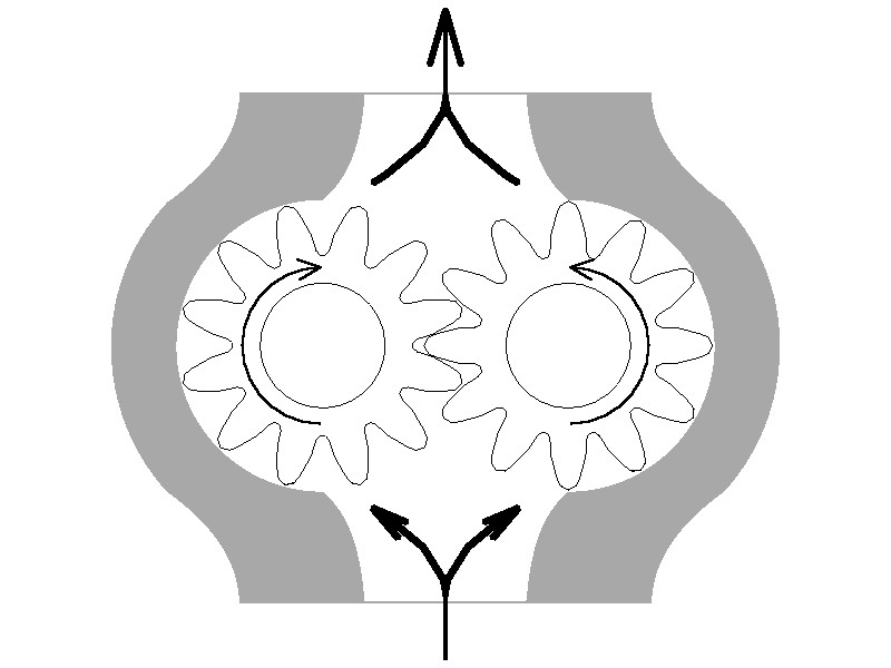
Simply put, gear pumps are positive displacement pumps and are the simplest type you can purchase. Positive displacement means that every time I rotate the shaft there is a fixed amount of oil coming out. In the diagram shown here, oil comes in the bottom and is pressurized by the gears and then moves out the top. The blue gear will spin clockwise. These pumps are small, inexpensive and will handle dirty oil well. As a result, they are the most common pump type on the market.
A piston pump is a variable displacement pump and will produce full flow to no flow depending on a variety of conditions. There is no direct link between shaft rotation and flow output. In the diagram below, there are eight pistons (mini cylinders) arranged in a circle. The movable end is attached to a swashplate which pushes and pulls the pistons in and out of the cylinder. The pistons are all attached to the rotating shaft while the swashplate stays fixed. Oil from the inlet flows into the cylinders as the swashplate is extending the pistons. When the swashplate starts to push the pistons back in, this oil is expelled to the outlet.
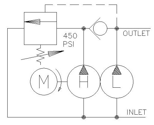
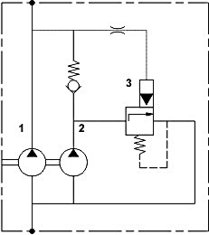
So, we don’t actually turn one of the pumps off. It is very difficult to mechanically disconnect the pump, but we do the next best thing. So earlier in the article I mentioned that pumps move oil they don’t create pressure. Keeping this in mind, we can simply recirculate the oil from the pressure side back to the tank side. Simple. So, let’s look at this as a schematic.
Luckily, turning off the pump is quite simple and only involves two components: a check valve and an unloader valve. The check valve is there to keep the higher-pressure oil from the low flow pump separate from the oil in the high flow pump. The higher-pressure oil from the low flow pump will shift the unloader valve by compressing the spring. This allows flow from the high flow pump to return to the suction line of the pump. Many pumps have this return line internal to the pump, so there is no additional plumbing needed. At this point, the high flow pump uses little to no power to perform this action. You will notice that the cylinder speed slows dramatically. As the log splits apart, the pressure may drop causing the unloader valve to close again. At this point, the flows will combine again. This process may repeat several times during a single split.
The graph above shows the overlay of a performance curve of a piston pump and two stage gear pumps. As you can see, the piston pump between 700 psi and 3000 psi will deliver the maximum HP that our engine can produce and as a result, it will have maximum speed. Unfortunately, it will also have maximum cost. If we are willing to sacrifice a little performance, the two-stage pump will work very well. Most of our work is done under 500 psi where the two pumps have identical performance. As pressure builds, the gear pump will be at a slight disadvantage, but with good performance. The amount of time we spend in this region of the curve is very little and it would be hard to calculate the time wasted.
After the pump on my log splitter died, I replaced it with a two-stage pump. While I was missing out on the full benefits of the piston pump, there was a tremendous increase in my output (logs/hr.). I noticed that instead of me waiting on the cylinder to be in the right position, I was now the hold up. I couldn’t get the logs in and positioned fast enough. What a difference!
As you go from a standard two-stage pump to your own custom design, you will find that you will need to add the check valve and unloader separately. However, there are many available cartridges manifold out there already that make this simple. Some even have relief valves built in!
Two stage pumps are wonderful creations! They allow for better utilization of pressure, flow and power by giving you two performance curve areas. They also show their versatility in conserving power which leads to energy savings while remaining inexpensive. A lot of these pumps come pre-made and preset, but you can make your own! See if your next project can get a boost from one of these wonderful devices.

This compact, two-stage, external gear pump is designed for use at elevated pressures and is ideal for press-type applications requiring fast approach/retract speeds and slower peak actuator work speeds due to horsepower limitations or safety constraints. Rotation is clockwise viewed from the Shaft end. The 1/2" shafts use 404 woodruff key. anmd the 5/8" Shafts use 3/16". 3600 RPM max. Maximum pressure 3,045 PSI.

The primary function of the hydraulic pump is to convert mechanical energy into fluid power energy. Hydraulic pumps can be grouped into two classes: fixed and variable displacement. We offer a wide selection of two-stage, PTO, manual hydraulic pumps and more. Shop the full selection below.
The cylinder is driven by hydraulic oil, under pressure, produced by a hydraulic pump. An engine, or electric motor, drives the pump shaft, and supplies the power for the system. The oil from the pump runs to a hydraulic valve, which provides control over the movement of the cylinder.
The oil source is a hydraulic reservoir (tank) which is connected directly to the inlet port of the pump. Most use AW32 viscosity (approx 10 wt.) hydraulic oil, which is of course an important part of any hydraulic system. There is a vented filler cap on the reservoir which allows air to “breathe” in and out. A simple air filter in it keeps dirt out.
A hydraulic relief valve controls the maximum pressure which can be created by the pump, and is a safety valve. It is usually located within the housing of the directional control valve. It is rarely in the pump. Without a relief, most hydraulic pumps will build pressure until something breaks, like a hose, or the cylinder, or the pump itself.
Most log splitters use a 2-stage gear pump which is a special type of hydraulic pump. They are rarely used in any other hydraulic systems. But they are widely available and relatively cheap because so many are sold for logsplitters.
Let’s start with the basics. Gear pumps are the most common, and least expensive type of hydraulic pump. They consist of 2 shafts, each with a gear which meshes with its twin to drive oil from the inlet port to the outlet or pressure port. Oil is trapped in the cavities between the gear teeth and carried around the outside of the gear toward the outlet port. The meshed gear teeth in the center keep oil from returning to the inlet side. One shaft sticks out of the housing and is driven by the engine. The other shaft is hidden within the pump housing. The one gear drives the other.
Two stage pumps give splitters great performance using small engines. A 2-stage pump consists of 2 gear pumps in a single housing, and a bypass valve. One gear set is about 3 times the size (length) of the second. When the valve is in neutral & system pressure is low, both gear sets are pumping oil into the system. With a “16 GPM” pump, they will pump 16 GPM when the pump shaft is rotated (by the engine) at 3400 RPM. That is, the combination of the outputs from both gear sets equals 16 GPM.
When the valve is shifted it moves the cylinder quite quickly. But when the log hits the wedge, the resistance increases, and pressure is backed up against the pump. Now the bypass valve comes into play. When the back pressure reaches 700 – 800 PSI, oil from the larger set of gears is allowed to pass back to the inlet side of the pump (at almost 0 PSI) rather than being forced out the pressure port. So the only oil being forced out is from the small gear set. This takes a lot less horsepower and allows the use of a reasonably small engine to develop the high pressure necessary to split wood, while giving the cylinder good speed when not under a heavy load (which is most of the time). The opening and closing of the bypass is automatic, activated by the oil pressure. It’s so smooth it’s usually difficult to notice it is happening. So 2-stage pumps give our log splitters the best of both: high pressure when we need it, and high speed the rest of the time.
We sometimes see home made log splitters with single stage pumps, often reused from another type of machine. They are usually quite slow unless a much bigger than normal engine is used.
The cylinder is the “actuator” of the system: it converts the hydraulic pressure and flow into force to split the wood, and speed to make it efficient. The larger the cylinder diameter the more force (tonnage) it puts out, but the slower it will go: it takes more oil to fill, and so takes longer.
The most common size for log splitters is “4 x 24″, 4″ bore by 24″ stroke. With 2500 PSI from the pump it can exert over 31,000 lbs of push force. To compare, a 5″ bore cylinder can produce 49,000 lbs force with the same pump, over 1 1/2 times as much. But the 5” cylinder will go 36% slower, which is why they are not common on ordinary splitters.
1. Pushed one way it shunts oil from the pump to the base port of the cylinder, causing it to extend. And it simultaneously allows oil from the rod-end port of the cylinder to flow into the return line.
2. When let go, the spool springs back to the neutral position; the oil from the pump is allowed straight through to the return port where it is recycled back to the tank, and the cylinder ports are blocked so the cylinder is stopped and held in position.
The relief valve consists of a heavy spring with a compression adjustment screw, and a ball or poppet against a seat. This is in a channel between the pressure inlet port and the return port, with the ball or poppet blocking the flow. If the oil pressure reaches the adjustment setting, perhaps 2500 PSI, it overcomes the spring pressure, the poppet backs off, and oil from the pump is allowed to bypass directly to the valve outlet, thus limiting the maximum oil pressure in the system. At normal working pressures, the relief remains closed and is not involved in the circuit.
The hydraulic oil for the system is stored in a tank, usually steel. Reservoirs serve two important functions: They allow the oil to settle any air bubbles and contamination particles; and they allow the oil to cool while it’s not circulating.
To provide sufficient cooling, the tank should be sized to hold at least one minute’s worth of oil. (16 gallons for a 16 GPM pump.) Oil which is too hot, 180F, will harden seals, and will be too thin to lubricate the spinning pump parts, causing early pump failure. We recommend 150F as the working maximum oil temperature.
The suction and return ports should be on the sides of the tank, a couple of inches above the bottom to avoid any sludge which may have settled there. The suction line should be low enough to never ingest any air, and the return should be low so as not to stir any air into the oil. Further, the 2 ports should be separated enough to avoid the hot returning oil from being immediately sucked back into the pump line.
Every good hydraulic system has a filter to remove fine contamination particles from the oil. The recommended rating is 10 microns, (10 microns equals 0.00039 inches; about 1/5 the diameter of a human hair). A filter this fine would plug the suction line, so it must be installed on the return, typically right at the tank return port.
Suction strainers in the tank are 100 micron or more, so can not catch the fine, damaging particles like the return filter. And if they get plugged they may starve the pump, greatly shortening its life. They are not recommended.
Hydraulic oil is blended with chemical additives beneficial for hydraulic systems. They help resist wear, shed contamination, maintain viscosity when cold, resist foaming, rust and oxidation, etc. Typical viscosity is around SAE 10, usually labelled AW32.
Hydraulic oil is not subjected to the burning temperatures of combustion engines, so it usually lasts a long time. The recommendation is to change oil if it is excessively dirty, or milky (water contamination) or smells bad or burned. If not, it’s better to just change the filter and save the cost of an oil change.
How to get more force? Either more pressure, or a larger cylinder. The pressure you probably can’t change much. Check the relief setting on your directional valve. It controls the maximum. We don’t suggest more than 2500 PSI, which is the practical maximum for most gear pumps. Yes they are sometimes rated at 3000 PSI or more. But that’s like driving your car 125 MPH. It may be able to do it, but all the time? Not such a good idea. Virtually all logsplitter pumps are rated for the same pressure. What’s the difference between pumps? Bigger gears, which produce more flow, which means more speed. And requires more horsepower to drive them. To get more force, you’ll need a larger bore cylinder. If you want the same speed as a smaller cylinder, you’ll need a larger pump, and probably a larger engine to drive it.
How to get more speed? Either more flow (GPM), or a smaller cylinder. The smaller cylinder won’t require more power, but will produce less force. More flow comes from a larger pump. So you’ll get the same force but will need to supply more horsepower to the new pump.

These 2 stage pumps are based on our Z-Class hydraulic pump platform - widely recognized as the market leader in industrial hydraulic pump technology. ZA Series air driven pumps are built to power medium to large-sized single-acting cylinders and other hydraulic tools.
A selection of valve and control options allow you to configure a pump for a wide range of demanding applications. Reservoir capacities of 1.2, 1.8, or 5.2 gallons are available, including a sight gauge for easy oil level monitoring.
Check that the pump shaft is rotating. Even though coupling guards and C-face mounts can make this difficult to confirm, it is important to establish if your pump shaft is rotating. If it isn’t, this could be an indication of a more severe issue, and this should be investigated immediately.
Check the oil level. This one tends to be the more obvious check, as it is often one of the only factors inspected before the pump is changed. The oil level should be three inches above the pump suction. Otherwise, a vortex can form in the reservoir, allowing air into the pump.
What does the pump sound like when it is operating normally? Vane pumps generally are quieter than piston and gear pumps. If the pump has a high-pitched whining sound, it most likely is cavitating. If it has a knocking sound, like marbles rattling around, then aeration is the likely cause.
Cavitation is the formation and collapse of air cavities in the liquid. When the pump cannot get the total volume of oil it needs, cavitation occurs. Hydraulic oil contains approximately nine percent dissolved air. When the pump does not receive adequate oil volume at its suction port, high vacuum pressure occurs.
This dissolved air is pulled out of the oil on the suction side and then collapses or implodes on the pressure side. The implosions produce a very steady, high-pitched sound. As the air bubbles collapse, the inside of the pump is damaged.
While cavitation is a devastating development, with proper preventative maintenance practices and a quality monitoring system, early detection and deterrence remain attainable goals. UE System’s UltraTrak 850S CD pump cavitation sensor is a Smart Analog Sensor designed and optimized to detect cavitation on pumps earlier by measuring the ultrasound produced as cavitation starts to develop early-onset bubbles in the pump. By continuously monitoring the impact caused by cavitation, the system provides a simple, single value to trend and alert when cavitation is occurring.
The oil viscosity is too high. Low oil temperature increases the oil viscosity, making it harder for the oil to reach the pump. Most hydraulic systems should not be started with the oil any colder than 40°F and should not be put under load until the oil is at least 70°F.
Many reservoirs do not have heaters, particularly in the South. Even when heaters are available, they are often disconnected. While the damage may not be immediate, if a pump is continually started up when the oil is too cold, the pump will fail prematurely.
The suction filter or strainer is contaminated. A strainer is typically 74 or 149 microns in size and is used to keep “large” particles out of the pump. The strainer may be located inside or outside the reservoir. Strainers located inside the reservoir are out of sight and out of mind. Many times, maintenance personnel are not even aware that there is a strainer in the reservoir.
The suction strainer should be removed from the line or reservoir and cleaned a minimum of once a year. Years ago, a plant sought out help to troubleshoot a system that had already had five pumps changed within a single week. Upon closer inspection, it was discovered that the breather cap was missing, allowing dirty air to flow directly into the reservoir.
A check of the hydraulic schematic showed a strainer in the suction line inside the tank. When the strainer was removed, a shop rag was found wrapped around the screen mesh. Apparently, someone had used the rag to plug the breather cap opening, and it had then fallen into the tank. Contamination can come from a variety of different sources, so it pays to be vigilant and responsible with our practices and reliability measures.
The electric motor is driving the hydraulic pump at a speed that is higher than the pump’s rating. All pumps have a recommended maximum drive speed. If the speed is too high, a higher volume of oil will be needed at the suction port.
Due to the size of the suction port, adequate oil cannot fill the suction cavity in the pump, resulting in cavitation. Although this rarely happens, some pumps are rated at a maximum drive speed of 1,200 revolutions per minute (RPM), while others have a maximum speed of 3,600 RPM. The drive speed should be checked any time a pump is replaced with a different brand or model.
Every one of these devastating causes of cavitation threatens to cause major, irreversible damage to your equipment. Therefore, it’s not only critical to have proper, proactive practices in place, but also a monitoring system that can continuously protect your valuable assets, such as UE System’s UltraTrak 850S CD pump cavitation senor. These sensors regularly monitor the health of your pumps and alert you immediately if cavitation symptoms are present, allowing you to take corrective action before it’s too late.
Aeration is sometimes known as pseudo cavitation because air is entering the pump suction cavity. However, the causes of aeration are entirely different than that of cavitation. While cavitation pulls air out of the oil, aeration is the result of outside air entering the pump’s suction line.
Several factors can cause aeration, including an air leak in the suction line. This could be in the form of a loose connection, a cracked line, or an improper fitting seal. One method of finding the leak is to squirt oil around the suction line fittings. The fluid will be momentarily drawn into the suction line, and the knocking sound inside the pump will stop for a short period of time once the airflow path is found.
A bad shaft seal can also cause aeration if the system is supplied by one or more fixed displacement pumps. Oil that bypasses inside a fixed displacement pump is ported back to the suction port. If the shaft seal is worn or damaged, air can flow through the seal and into the pump’s suction cavity.
As mentioned previously, if the oil level is too low, oil can enter the suction line and flow into the pump. Therefore, always check the oil level with all cylinders in the retracted position.
If a new pump is installed and pressure will not build, the shaft may be rotating in the wrong direction. Some gear pumps can be rotated in either direction, but most have an arrow on the housing indicating the direction of rotation, as depicted in Figure 2.
Pump rotation should always be viewed from the shaft end. If the pump is rotated in the wrong direction, adequate fluid will not fill the suction port due to the pump’s internal design.
A fixed displacement pump delivers a constant volume of oil for a given shaft speed. A relief valve must be included downstream of the pump to limit the maximum pressure in the system.
After the visual and sound checks are made, the next step is to determine whether you have a volume or pressure problem. If the pressure will not build to the desired level, isolate the pump and relief valve from the system. This can be done by closing a valve, plugging the line downstream, or blocking the relief valve. If the pressure builds when this is done, there is a component downstream of the isolation point that is bypassing. If the pressure does not build up, the pump or relief valve is bad.
If the system is operating at a slower speed, a volume problem exists. Pumps wear over time, which results in less oil being delivered. While a flow meter can be installed in the pump’s outlet line, this is not always practical, as the proper fittings and adapters may not be available. To determine if the pump is badly worn and bypassing, first check the current to the electric motor. If possible, this test should be made when the pump is new to establish a reference. Electric motor horsepower is relative to the hydraulic horsepower required by the system.
For example, if a 50-GPM pump is used and the maximum pressure is 1,500 psi, a 50-hp motor will be required. If the pump is delivering less oil than when it was new, the current to drive the pump will drop. A 230-volt, 50-hp motor has an average full load rating of 130 amps. If the amperage is considerably lower, the pump is most likely bypassing and should be changed.
Figure 4.To isolate a fixed displacement pump and relief valve from the system, close a valve or plug the line downstream (left). If pressure builds, a component downstream of the isolation point is bypassing (right).
The most common type of variable displacement pump is the pressure-compensating design. The compensator setting limits the maximum pressure at the pump’s outlet port. The pump should be isolated as described for the fixed displacement pump.
If pressure does not build up, the relief valve or pump compensator may be bad. Prior to checking either component, perform the necessary lockout procedures and verify that the pressure at the outlet port is zero psi. The relief valve and compensator can then be taken apart and checked for contamination, wear, and broken springs.
Install a flow meter in the case drain line and check the flow rate. Most variable displacement pumps bypass one to three percent of the maximum pump volume through the case drain line. If the flow rate reaches 10 percent, the pump should be changed. Permanently installing a flow meter in the case drain line is an excellent reliability and troubleshooting tool.
Ensure the compensator is 200 psi above the maximum load pressure. If set too low, the compensator spool will shift and start reducing the pump volume when the system is calling for maximum volume.
Performing these recommended tests should help you make good decisions about the condition of your pumps or the cause of pump failures. If you change a pump, have a reason for changing it. Don’t just do it because you have a spare one in stock.
Conduct a reliability assessment on each of your hydraulic systems so when an issue occurs, you will have current pressure and temperature readings to consult.
Al Smiley is the president of GPM Hydraulic Consulting Inc., located in Monroe, Georgia. Since 1994, GPM has provided hydraulic training, consulting and reliability assessments to companies in t...


 8613371530291