
typical hydraulic pump efficiency supplier

In a condition-based maintenance environment, the decision to change out a hydraulic pump or motor is usually based on remaining bearing life or deteriorating efficiency, whichever occurs first.
Despite recent advances in predictive maintenance technologies, the maintenance professional’s ability to determine the remaining bearing life of a pump or motor, with a high degree of accuracy, remains elusive.
Deteriorating efficiency on the other hand is easy to detect, because it typically shows itself through increased cycle times. In other words, the machine slows down. When this occurs, quantification of the efficiency loss isn’t always necessary. If the machine slows to the point where its cycle time is unacceptably slow, the pump or motor is replaced. End of story.
In certain situations, however, it can be helpful, even necessary, to quantify the pump or motor’s actual efficiency and compare it to the component’s native efficiency. For this, an understanding of hydraulic pump and motor efficiency ratings is essential.
There are three categories of efficiency used to describe hydraulic pumps (and motors): volumetric efficiency, mechanical/hydraulic efficiency and overall efficiency.
Volumetric efficiency is determined by dividing the actual flow delivered by a pump at a given pressure by its theoretical flow. Theoreticalflow is calculated by multiplying the pump’s displacement per revolution by its driven speed. So if the pump has a displacement of 100 cc/rev and is being driven at 1000 RPM, its theoretical flow is 100 liters/minute.
Actualflow has to be measured using a flow meter. If when tested, the above pump had an actual flow of 90 liters/minute at 207 bar (3000 PSI), we can say the pump has a volumetric efficiency of 90% at 207 bar (90 / 100 x 100 = 90%).
Its volumetric efficiency used most in the field to determine the condition of a hydraulic pump - based on its increase in internal leakage through wear or damage. But without reference to theoretical flow, the actual flow measured by the flow meter would be meaningless.
A pump’s mechanical/hydraulic efficiency is determined by dividing thetheoretical torque required to drive it by the actual torque required to drive it. A mechanical/hydraulic efficiency of 100 percent would mean if the pump was delivering flow at zero pressure, no force or torque would be required to drive it. Intuitively, we know this is not possible, due to mechanical and fluid friction.
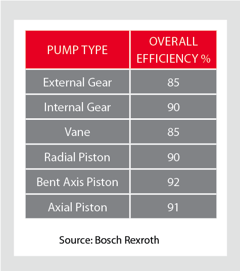
Table 1. The typical overall efficiencies of hydraulic pumps, as shown above, are simply the product of volumetric and mechanical/hydraulic efficiency.Source: Bosch Rexroth
Like theoretical flow, theoretical drive torque can be calculated. For the above pump, in SI units: 100 cc/rev x 207 bar / 20 x p = 329 Newton meters. But like actual flow, actual drive torque must be measured and this requires the use of a dynamometer. Not something we can - or need - to do in the field. For the purposes of this example though, assume the actual drive torque was 360 Nm. Mechanical efficiency would be 91% (329 / 360 x 100 = 91%).
Overall efficiency is simply the product of volumetric and mechanical/hydraulic efficiency. Continuing with the above example, the overall efficiency of the pump is 0.9 x 0.91 x 100 = 82%. Typical overall efficiencies for different types of hydraulic pumps are shown in the Table 1.
System designers use the pump manufacturers’ volumetric efficiency value to calculate the actual flow a pump of a given displacement, operating at a particular pressure, will deliver.
As already mentioned, volumetric efficiency is used in the field to assess the condition of a pump, based on the increase in internal leakage due to wear or damage.
When calculating volumetric efficiency based on actual flow testing, it’s important to be aware that the various leakage paths within the pump are usually constant. This means if pump flow is tested at less than full displacement (or maximum RPM) this will skew the calculated efficiency - unless leakage is treated as a constant and a necessary adjustment made.
For example, consider a variable displacement pump with a maximum flow rate of 100 liters/minute. If it was flow tested at full displacement and the measured flow rate was 90 liters/minute, the calculated volumetric efficiency would be 90 percent (90/100 x 100). But if the same pump was flow tested at the same pressure and oil temperature but at half displacement (50 L/min), the leakage losses would still be 10 liters/minute, and so the calculated volumetric efficiency would be 80 percent (40/50 x 100).
The second calculation is not actually wrong, but it requires qualification: this pump is 80 percent efficient at half displacement. Because the leakage losses of 10 liters/minute are nearly constant, the same pump tested under the same conditions will be 90 percent efficient at 100 percent displacement (100 L/min) - and 0 percent efficient at 10 percent displacement (10 L/min).
To help understand why pump leakage at a given pressure and temperature is virtually constant, think of the various leakage paths as fixed orifices. The rate of flow through an orifice is dependant on the diameter (and shape) of the orifice, the pressure drop across it and fluid viscosity. This means that if these variables remain constant, the rate of internal leakage remains constant, independent of the pump"s displacement or shaft speed.
Overall efficiency is used to calculate the drive power required by a pump at a given flow and pressure. For example, using the overall efficiencies from the table above, let us calculate the required drive power for an external gear pump and a bent axis piston pump at a flow of 90 liters/minute at 207 bar:
As you’d expect, the more efficient pump requires less drive power for the same output flow and pressure. With a little more math, we can quickly calculate the heat load of each pump:
No surprise that a system with gear pumps and motors requires a bigger heat exchanger than an equivalent (all other things equal) system comprising piston pumps and motors.

Gear pumps GP1K Group 1 is an Ideal solution for hydraulic power packs. Modern technologies and many years of experience of the HYDROSILA company allow us to create pumps with high ...
The radial piston pump type R consists of valve-controlled pump elements arranged in star form around an eccentric. For large flow rates, up to 42 pump elements can be ...
PGP 500 pumps offer superior performance, high efficiency and low noise operation at high operating pressures. They are produced in four frame sizes (PGP 502, PGP 505,PGP ...
... Series pump offers variable displacement axial piston pumps for open-circuit applications. Featuring a compact footprint and continuous operating pressure of up to 4,060 psi, PD piston ...

Hydraulic systems are in general members of the fluid power branch of power transmission. Hydraulic pumps are also members of the hydraulic power pack/hydraulic power unit family. Hydraulic units are encased mechanical systems that use liquids for hydraulics.
The hydraulic systems that hydraulic pumps support exist in a range of industries, among them agriculture, automotive manufacturing, defense contracting, excavation, and industrial manufacturing. Within these industries, machines and applications that rely on hydraulic pumps include airplane flaps, elevators, cranes, automotive lifts, shock absorbers, automotive brakes, garage jacks, off-highway equipment, log splitters, offshore equipment, hydraulic motors/hydraulic pump motors, and a wide range of other hydraulic equipment.
When designing hydraulic pumps, manufacturers have many options from which to choose in terms of material composition. Most commonly, they make the body of the pump–the gears, pistons, and hydraulic cylinders–from a durable metal material. This metal is one that that can hold up against the erosive and potentially corrosive properties of hydraulic fluids, as well as the wear that comes along with continual pumping. Metals like this include, among others, steel, stainless steel, and aluminum.
First, what are operating specifications of their customer? They must make sure that the pump they design matches customer requirements in terms of capabilities. These capabilities include maximum fluid flow, minimum and maximum operating pressure, horsepower, and operating speeds. Also, based on application specifications, some suppliers may choose to include discharge sensors or another means of monitoring the wellbeing of their hydraulic system.
Next, what is the nature of the space in which the pump will work? Based on the answer to this question, manufacturers will design the pump with a specific weight, rod extension capability, diameter, length, and power source.
Manufacturers must also find out what type of substance does the customer plan on running through the pumps. If the application calls for it, manufacturers can recommend operators add other substances to them in order to decrease the corrosive nature of certain hydraulic fluids. Examples of such fluids include esters, butanol, pump oils, glycols, water, or corrosive inhibitors. These substances differ in operating temperature, flash point, and viscosity, so they must be chosen with care.
All hydraulic pumps are composed in the same basic way. First, they have a reservoir, which is the section of the pump that houses stationary fluid. Next, they use hydraulic hoses or tubes to transfer this fluid into the hydraulic cylinder, which is the main body of the hydraulic system. Inside the cylinder, or cylinders, are two hydraulic valves and one or more pistons or gear systems. One valve is located at each end; they are called the intake check/inlet valve and the discharge check/outlet valve, respectively.
Hydraulic pumps operate under the principle of Pascal’s Law, which states the increase in pressure at one point of an enclosed liquid in equilibrium is equally transferred to all other points of said liquid.
To start, the check valve is closed, making it a normally closed (NC) valve. When the check is closed, fluid pressure builds. The piston forces the valves open and closes repeatedly at variable speeds, increasing pressure in the cylinder until it builds up enough to force the fluid through the discharge valve. In this way, the pump delivers sufficient force and energy to the attached equipment or machinery to move the target load.
When the fluid becomes pressurized enough, the piston withdraws long enough to allow the open check valve to create a vacuum that pulls in hydraulic fluid from the reservoir. From the reservoir, the pressurized fluid moves into the cylinder through the inlet. Inside the cylinder, the fluid picks up more force, which it carries over into the hydraulic system, where it is released through the outlet.
Piston pumps create positive displacement and build pressure using pistons. Piston pumps may be further divided into radial piston pumps and axial piston pumps.
Radial pumps are mostly used to power relatively small flows and very high-pressure applications. They use pistons arranged around a floating center shaft or ring, which can be moved by a control lever, causing eccentricity and the potential for both inward and outward movement.
Axial pumps, on the other hand, only allow linear motion. Despite this, they are very popular, being easier and less expensive to produce, as well as more compact in design.
Gear pumps, or hydraulic gear pumps, create pressure not with pistons but with the interlocking of gear teeth. When teeth are meshed together, fluid has to travel around the outside of the gears, where pressure builds.
External gear pumps facilitate flow by enlisting two identical gears that rotate against each other. As liquid flows in, it is trapped by the teeth and forced around them. It sits, stuck in the cavities between the teeth and the casing, until it is so pressurized by the meshing of the gears that it is forced to the outlet port.
Internal gear pumps, on the other hand, use bi-rotational gears. To begin the pressurizing process, gear pumps first pull in liquid via a suction port between the teeth of the exterior gear, called the rotor, and the teeth of the interior gear, called the idler. From here, liquid travels between the teeth, where they are divided within them. The teeth continue to rotate and mesh, both creating locked pockets of liquid and forming a seal between the suction port and the discharge port. Liquid is discharged and power is transported once the pump head is flooded. Internal gears are quite versatile, usable with a wide variety of fluids, not only including fuel oils and solvents, but also thick liquids like chocolate, asphalt, and adhesives.
Various other types of hydraulic pumps include rotary vane pumps, centrifugal pumps, electric hydraulic pumps, hydraulic clutch pumps, hydraulic plunger pumps, hydraulic water pumps, hydraulic ram pumps, portable 12V hydraulic pumps, hydraulic hand pumps, and air hydraulic pumps.
Rotary vane pumps are fairly high efficiency pumps, though they are not considered high pressure pumps. Vane pumps, which are a type of positive-displacement pump, apply constant but adjustable pressure.
Centrifugal pumps use hydrodynamic energy to move fluids. They feature a rotating axis, an impeller, and a casing or diffuser. Most often, operators use them for applications such as petroleum pumping, sewage, petrochemical pumping, and water turbine functioning.
Electric hydraulic pumps are hydraulic pumps powered by an electric motor. Usually, the hydraulic pump and motor work by turning mechanisms like impellers in order to create pressure differentials, which in turn generate fluid movement. Nearly any type of hydraulic pump can be run with electricity. Most often, operators use them with industrial machinery.
Hydraulic clutch pumps help users engage and disengage vehicle clutch systems. They do so by applying the right pressure for coupling or decoupling shafts in the clutch system. Coupled shafts allow drivers to accelerate, while decoupled shafts allow drivers to decelerate or shift gears.
Hydraulic ram pumps are a type of hydraulic pump designed to harness hydropower, or the power of water, to elevate it. Featuring only two moving hydraulic parts, hydraulic ram pumps require only the momentum of water to work. Operators use hydraulic ram pumps to move water in industries like manufacturing, waste management and sewage, engineering, plumbing, and agriculture. While hydraulic ram pumps return only about 10% of the water they receive, they are widely used in developing countries because they do not require fuel or electricity.
Hydraulic water pumps are any hydraulic pumps used to transfer water. Usually, hydraulic water pumps only require a little bit of energy in the beginning, as the movement and weight of water generate a large amount of usable pressure.
Air hydraulic pumps are hydraulic pumps powered by air compressors. In essence, these energy efficient pumps work by converting air pressure into hydraulic pressure.
Hydraulic pumps are useful for many reasons. First, they are simple. Simple machines are always an advantage because they are less likely to break and easier to repair if they do. Second, because fluid is easy to compress and so quick to create pressure force, hydraulic pumps are very efficient. Next, hydraulic pumps are compact, which means they are easy to fit into small and oddly shaped spaces. This is especially true in comparison to mechanical pumps and electrical pumps, which manufacturers cannot design so compactly. Speaking of design, another asset of hydraulic pumps is their customizability. Manufacturers can modify them easily. Likewise, hydraulic pumps are very versatile, not only because they are customizable, but also because they can work in places where other types of pump systems can’t, such as in the ocean. Furthermore, hydraulic pumps can produce far more power than similarly sized electrical pumps. Finally, these very durable hydraulic components are much less likely to explode than some other types of components.
To make sure that your hydraulic pumps stay useful for a long time, you need to treat them with care. Care includes checking them on a regular basis for problems like insufficient fluid pressure, leaks, and wear and tear. You can use diagnostic technology like discharge sensors to help you with detect failures and measure discharge pressure. Checking vibration signals alone is often not enough.
To keep yourself and your workers safe, you need to always take the proper precautions when operating or performing maintenance and repairs on your hydraulic pumps. For example, you should never make direct contact with hydraulic fluid. For one, the fluid made be corrosive and dangerous to your skin. For two, even if the pump isn’t active at that moment, the fluid can still be pressurized and may potentially harm you if something goes wrong. For more tips on hydraulic pump care and operation, talk to both your supplier and OSHA (Occupational Safety and Health Administration).
Pumps that meet operating standards are the foundation of safe and effective operations, no matter the application. Find out what operating standards your hydraulic pumps should meet by talking to your industry leaders.
The highest quality hydraulic pumps come from the highest quality hydraulic pump manufacturers. Finding the highest quality hydraulic pump manufacturers can be hard, which is why we have we listed out some of our favorites on this page. All of those whom we have listed come highly recommended with years of experience. Find their information nestled in between these information paragraphs.
Once you have put together you list, get to browsing. Pick out three or four hydraulic pump supply companies to which you’d like to speak, then reach out to each of them. After you’ve spoken with representatives from each company, decide which one will best serve you, and get started on your project.

Low- and high-speed tests show that pump and motor performance can vary widely, depending on the speed and pressure. That’s critically important in electro-hydraulic actuators and electric-motor drives.
Hydraulic component manufacturers generally publish pump and motor data that reflect optimal performance under ideal operating conditions. But experienced design engineers know that it is extremely difficult to obtain efficiency or performance data for less-than-perfect, real-world conditions. It even gets harder when looking at new concepts, such as electrohydraulic actuators, which run at very low as well as high speeds. There are almost no data for these applications.
To address this information void, Innas recently tested and benchmarked the performance of a number of different pumps and motors running over a range of pressures and flows. We specifically targeted the types of pumps being considered for electrohydraulic actuators designed for implement systems. Moog, for instance, is advocating their radial-piston pump, whereas Rexroth is focusing on axial-piston pumps. Others are looking at gear pumps, both internal and external.
Our published report shows that current pumps and motors are not made for electrohydraulic actuators. They are built for more or less constant-speed operation, driven by a diesel engine or an electric motor, generally running at 1,500 to 1,800 rpm.
Granted, many of the units tested are specified to not operate below a certain minimum speed simply because of significant wear or excessive internal leakage. Nonetheless, these limitations severely hinder their application in EHAs. Both dead-band and severe friction will inhibit the precise operation of hydraulic cylinders, especially because controllability will become much more important in the future. For this reason, we have tested these machines over a wide range of operating conditions.
Results indicate that there is a dire need for the development of new concepts. The Innas floating-cup principle represents one such advancement. Its mirrored design with 24 pistons, very short strokes, a small displacement angle and hydrostatic lubrication provides extremely high efficiency even at start-up. And it can precisely control significant loads at speeds of just 2 to 3 rpm with virtually no wear. But we strongly believe that more breakthroughs are required. We plan to continue to measure the performance of other pumps and motors, and publish updated results on our web site.
The report contains results for performance measurements on eight different hydrostatic devices: three piston pumps, three piston motors, and two gear pumps. Important specifications are shown in the accompanying table. The piston-type units have from 7 to 24 pistons. From a physical point of view, the number of pistons is similar to the number of teeth in a gear pump. Derived geometric displacement volumes range from 23.7 to 32.7 cc/rev.
Each pump and motor was measured using a unique test bench, developed by Innas engineers, which can operate a hydrostatic device at speeds ranging from 5,000 rpm to less than 0.01 rpm. More details are available in the sidebar, “Novel test rig is incredibly versatile.”
To analyze the different devices, we looked at the measurement results. The three most important quantities used to describe the performance of the test subjects are the overall efficiency ηt, torque loss Tloss, and leakage Q3. Efficiency and torque loss are derived from the measured data, while leakage is measured directly.
It is important to note that several definitions used here differ from the current standard for measuring the performance of hydrostatic machines as described in ISO 4409:2019 and ISO 4391 — in particular the compressibility correction factors a1 and a2. A large group of experts from around the world agree with the need for these new efficiency definitions.
In a pump, mechanical power converts into hydraulic power, while a motor works the other way around. Overall efficiency ηt is the ratio at which power is converted; for a pump:
The difference in sign is similar to the difference in sign for the efficiencies: torque drives a pump to generate pressure and flow, while pressure and flow drives a motor to generate torque. The theoretical torque will thus be lower than the measured torque for pumps, to overcome friction and pressure ripples, and the opposite for motors. The theoretical torque can be calculated using:
with Vmin the dead volume per cylinder, and ∆V the geometric displacement volume per piston. To compare the torque loss of pumps and motors of different sizes, torque loss can be normalized. The normalized torque loss TNloss is defined as 1 − Tth/T for a pump and 1 – T/Tth for a motor.
Overall efficiencies of the different pumps and motors were determined based on the above equations. The results for various shaft speeds at an operating pressure of 200 bar are shown in the Overall Efficiency graph. All of the tested subjects followed the same trend: Efficiency is low at low operating speeds; increases rapidly until maximum efficiency is reached somewhere between 1,000 and 2,000 rpm; and as shaft speed increases further, efficiency decreases, but at a much lower rate.
At this pressure, the highest peak efficiency of almost 0.96 was realized by the Innas pump at 1,000 rpm, while the Moog pump had the lowest peak efficiency of 0.87 at 1,500 rpm. One outlier is the KYB motor’s measurement point at 2,000 rpm. Here, efficiency decreases much faster than was expected. However, the unit was running near its maximum rated operating speed, which causes additional torque loss and leakage.
Overall, the torque loss shows a similar trend for motors and pumps. Below 1 rpm (see logarithmic plot) losses appear to be constant. At some point, the torque loss quickly decreases for increasing shaft speeds, until reaching a minimum. From this speed onwards, the torque loss increases again, but at a slower rate. This trend is very much in accordance with the Stribeck curve, and the three sections describe the transition from coulomb friction (boundary lubrication), to mixed friction, and viscous friction (hydrodynamic lubrication), respectively.
The five pumps show larger differences with respect to each other. Overall, the Innas pump has the lowest torque loss at this pressure, especially in the low speed range. This can be explained by the fact that this is a floating-cup type pump, which has almost no contact between the piston and bore, and thus very little coulomb friction. In the viscous-friction section, torque losses in the Rexroth, Eckerle, and Innas pumps increase at roughly the same rate. Torque loss for the Moog pump increases at a faster rate, while the torque loss of the Marzocchi seems relatively constant at higher operating speeds.
The graphs show that torque loss is more or less constant at operating speeds below 1 rpm, due to coulomb friction. During the low-speed measurements, each unit can be tested during both pump and motor operation. (Because the Eckerle pump is an internal gear pump, it cannot be tested as a motor.) For most piston machines the torque loss due to coulomb friction is larger when it is driven as a pump. The exception being the Brevini, which has more or less the same torque loss for both directions.
This can be explained by the direction in which the piston moves during the high pressure stroke. When operated as a pump, the piston pushes the barrel to the portplate during the high pressure stroke, increasing the friction between those two surfaces and, therefore, the torque loss. When operated as a motor, the piston pulls the barrel away from the portplate, decreasing friction.
The highest torque loss was found on the Rexroth pump, which loses up to 60% of torque at these operating speeds. It is worth noting that the two Rexroth units are, apart from silencing grooves in the portplates, the same product. This was confirmed by comparing the torque losses when they were driven in the same direction.
The normalized torque loss of the Innas pump during low speed motor operation becomes less than zero. In other words, more torque was delivered to the shaft than the theoretical maximum. At these low speeds, leakage will be larger than the amount of displaced oil. In this case, an additional pump provides the right pressure level. Unfortunately, the calculations no longer apply in this situation, making it impossible to derive the overall efficiency. This approach emulates the behavior of units as part of a larger hydraulic network, which is often the case. It is currently hypothesized that the pressure delivered by this supply pump affects torque on the test specimen’s shaft as well. Further research will be needed to determine why this is the case, and what it means for further analyses.
Results also show that at these low speeds there is a significant variation in torque loss at different angular shaft positions. In the case of pumps, this normalized torque is larger than 1, meaning that a certain amount of additional torque is needed to overcome the friction. Some of the tested specimens needed as much as 80% extra torque to operate at this speed. In the case of motors, the normalized torque is less than 1, meaning that less torque is provided by the supplied oil. One unit showed a torque loss as much as 30%.
The leakage flow rate from the rotary group to the pump or motor housing is measured directly in the test bench. (Note that the gear pumps do not have an external leakage port, so leakage cannot be measured.) Internal leakage affects the total output flow rate and, thus, the efficiency calculations. Measured leakage for each device at 200 bar showed that for most, leakage increases slightly for increasing shaft speeds. This makes sense, because increasing the shaft speed will linearly increase the amount of displaced oil. However, the relatively constant leakage flow rates at low operating speeds suggest that it does not only depend on shaft speed. A constant leak flow generally means that the gap through which oil leaks does not change much, indicating that this is probably caused by the precision with which the parts have been made and how accurately they fit together.
Similar to the low speed torque losses, the Low Speed Leakage Flow Rate graph shows average leakage conditions for measurements at speeds less than 1 rpm. Tests showed a sizeable variation in leakage between the different measurements. Main factors for these larger ranges seem to be the oil temperature (which is difficult to control during low speed measurements) and the case pressure (mainly for the Moog pump).
Even though there is a significant spread in the flow rate measurements at different low speeds, leakage is generally higher during motor operation for most machines. When operated as a pump, the piston pushes the barrel to the portplate during the high pressure stroke, decreasing the size of this leakage path. When operated as a motor, the piston pulls the barrel away from the portplate, which allows for more leakage. Exceptions are the Innas pump, which has more or less equal leakage in both directions; and the Brevini motor, which has more leakage when driven as a pump than as a motor.
The Innas test bench can operate hydrostatic pumps and motors over an extremely wide speed range — from 5,000 rpm to less than 0.01 rpm — thanks to two different types of actuators.
After high-speed performance tests, low-speed tests are performed by shifting the coupling and connecting the linear actuator. The integrated set-up ensures that the test object, all sensors and hydraulic lines remain on the test bench. Additionally, the oil and pump or motor remain at warm operating temperatures. During low-speed measurements, the linear actuator first makes a downward stroke followed by an upward stroke. Thus, the unit is tested both as a motor and as a pump.

Although many detractors sneer at the idea of hydraulic efficiency, right-sizingcomponents, proper system design and moderntechnology can go a long way to achieving system efficiency.
“Hydraulic efficiency”is a term alluding similar sentiments to “exact estimate” or “scientific belief.” It’s not that hydraulic efficiency is an oxymoron, per se, but these aren’t traditionally two words that make sense shoulder to shoulder. If efficiency was your top benefit on the list of machine requirements, fluid power wouldn’t have been on your short list of options, at least in the past half-century or longer.
Efficiency is a word now more commonly familiar to us, thanks to the escalation of green values—especially those defining the way we use natural resources. No longer can we take a limitless and inexpensive source of energy for granted, nor can we abuse the dirty sources of inexpensive energy at the expense of our precious environment. We must take full advantage of our energy resources to achieve the work required for maintaining our standard of living, while reducing associated waste along the way.
What is efficiency?I define efficiency as work-in minus work-out. Essentially, it’s the differential between the energy your process requires and the energy input required to achieve that process. Your process could be stamping, rolling, injecting, moving, pressing or any other mechanical function capable of being achieved in a rotational or linear motion. If you’re running a punch press, for example, the machine efficiency is defined as the current draw of the pump’s motor minus the combined force and velocity of the punch die.
Most machines are designed to convert energy from one form to another, which can sometimes occur multiple times. Because of the Laws of Thermodynamics, you cannot change energy from one form to another without creating waste energy, and this is a fact regardless of the energy transformation taking place. In the case of a hydraulic machine, you must convert electrical energy to mechanical energy within the electric motor, resulting in partial waste. Then you must convert mechanical energy into hydraulic energy within the pump, resulting in partial waste. Then you must convert hydraulic energy back into mechanical energy at your cylinder or hydraulic motor, resulting in partial waste.
The amount of energy wasted in the above example could be staggering, especially if you’re using an old machine with old components. Let’s say you have a 10-hp electric motor—and keep in mind electric motors are rated on power consumption, not power output. Your old motor might have an efficiency of 85%, meaning it will produce 8.5 hp at its shaft, the other 1.5 hp being wasted as pure heat.
In your old power unit, you have a worn and tired gear pump. When new, a gear pump is lucky to have 80% efficiency, so I’ll be generous to throw 75% at this example, since gear pumps become less efficient over their lifetimes. So this pump can convert only 6.4 of the motor’s 8.5-hp shaft output into usable hydraulic energy. The rest of the energy is, you guessed it, wasted as pure heat. We’ve now lost 36% of the electrical energy inputted, and we haven’t even done anything yet.
Just to be intentionally derisive, I’m going to choose a hydraulic motor as our actuator; a gerotor motor to be exact. These motors come at a modest price and perform at a modest level. They were a clever design back in the day, but have high leakage to lubricate the myriad components, and they leak even more if you operate them outside their optimum torque and speed curve. Leakage, I should note, is a designed element of most hydraulic components, based on gaps and clearances with internal moving parts, which is required to lubricate that component. More moving parts or higher clearances means more leakage, and I should further note, any fluid lost to leakage carries with it pure heat equal to the pressure and flow of the leakage.
Now that I’ve blasted gerotor motors, I’ll back it up by saying they’re often incapable of reaching 80% efficiency. There are some versions of these “orbital” motors, like the disc valve variant, which can be close to 90% efficient, but it would be only within a tiny window of flow and pressure. I’ll stick with 80% for this example, which is generous. With the 6.4 hydraulic horsepower we havein our system, we’re left with 5.1 hp at the hydraulicmotor’s shaft.
So with barely half of our input energy making its way to the output stage, it’s easy to see why I’m dubious of “hydraulic efficiency.” So why use hydraulics when we could have powered our machine straight from the electric motor and take advantage of 8.5 hp instead of 5.1? In that answer lies the reason hydraulics are awesome; with $300 worth of valving, you can infinitely vary torque and speed, and reverse direction. Our electric motor would require sophisticated electronic control to achieve the same features.
To be fair, I’m using one of the worst-case examples for hydraulic efficiency. Not only are there more efficient components available than gear pumps and orbital motors, there are ingenious approaches to using hydraulic components. Furthermore, recent advances in electronic control have not ignored the fluid power industry, and there are some tricks to further improve hydraulic efficiency.
Pressure compensated pumps are set to a particular standby pressure, and when this pressure is reached, the pump reduces flow until downstream pressure drops below that standby pressure. Image courtesy of CD Industrial Group
I can’t stress enough that a hydraulic machine is really just an energy conversion device, and when you can convert your input energy into usable force with as little heat waste as possible, you’re on the right track. A pump converts the mechanical energy of the prime mover into hydraulic energy in the form of pressure and flow. If I were to recommend one component you blow the bankroll on, it would be the pump.
A piston pump, especially a high-quality one, can be 95% efficient at converting input energy into hydraulic energy. Not only does this pump provide 27% more available hydraulic energy than our old gear pump, it creates 80% less waste heat than it, reducing or eliminating cooling requirements.
Not only does an efficient pump help, an efficient design works wonders. If you have a fixed displacement pump on a flow control, any unused fluid is wasted as heat. For example, take even our 95% efficient fixed piston pump, giving us 9.5 gpm out of a theoretical 10 gpm. If your downstream priority flow control valve is set to 5 gpm, 4.5 gpm is bypassed to tank. However, all of the 9.5 gpm is still being created at full system pressure, and what’s dumped to tank is lost as heat. So now our 95% efficient pump is helping create a 50% inefficient system.
A load-sensing pump will provide only the pressure and flow required of the circuit and actuator, with only a few hundred psi worth of pressure drop as the waste by-product. Image courtesy of CD Industrial Group
To get around this, pressure compensation was created. A pressure compensated pump is set to a particular standby pressure, and when this pressure is reached, the pump reduces flow until downstream pressure drops below that standby pressure. For example, if you have a 10 gpm pump set at 3,000 psi, and flow is restricted below 10 gpm, the pump will reduce its displacement to exactly match the downstream flow and pressure drop at 3,000 psi. Essentially, the pump only produces the flowbeing asked for, no more, but always at 3,000 psi.
But what if we only want 1,000 psi for a particular operation? Well, you could use a pressure-reducing valve, but the pump is still producing 3,000 psi, so you’re not saving any energy. To remedy this, the load-sensing pump was invented. A load sensing pump has an additional compensator that is plumbed downstream of the metering valve. This configuration allows it to measure load pressure and compare it to compensator pressure. The result is the pump will provide only the pressure and flow required of the circuit and actuator, with only a few hundred psi worth of pressure drop as the waste by-product.
The use of variable speed technology can dramatically increase hydraulic efficiency. Here, the new Green Hydraulic Power units use Siemen’s SINAMICS variable speed servo pump drive to increase efficiency by up to 70%.
Recent advancements in control technology have resulted in a similar concept of pressure and flow management, but using a combination of fixed displacement pumps, servo or VFD motors and pressure transducers. The pressure transducers measure pressure after the pump and after the metering valves, and PLC gives the signal to rotate the pump at a speed only fast enough to achieve the desired pressure and flow. It’s quite an advanced technology, and has progressed to the point a pump could hold a stationary load and rotate fractional speed just to compensate for leakage. Another advantage to this technology is that the motor doesn’t even turn when no energy is required, and then again only with the energy required by demand of the hydraulic system.
Aside from choosing efficient pump designs, using efficient hydraulic actuators is the next best place to continue. Not much can be said of hydraulic cylinders, because most are close to 100% efficient already, depending on sealing technology. But just like with your hydraulic pump, the hydraulic motor has many variations, each with their own contribution to overall efficiency.
So for the most part, hydraulics is not an efficient technology. But neither are gasoline-powered cars, and millions of those are sold every day, because there is no better option for their task. Regardless, efficiency in hydraulics is progressing, and advancements in materials and technologies will further that. As long as you are aware of what it takes to create “hydraulic efficiency,” the term won’t seem curious like “seriously funny” or “virtual reality.”
Editor"s Note: This is the first in a six-part series on centrifugal pump efficiency. For other articles in this series, clickCentrifugal Pump Efficiency series.
In this multi-part series, we will investigate several aspects of centrifugal pump efficiency. First, I will define efficiency and give some examples. Next, I will examine some of the design criteria that ultimately dictate the efficiency exhibited by a particular pump.
I will also try to make that somewhat nebulous quantity, known as specific speed, more meaningful. I will illustrate its effect on the shape of a pump’s performance curve and overall pump efficiency.
Next, I will explain the contributions of individual pump components to a pump’s overall efficiency and show why the combined efficiency of a pump and its driver is the product, not the average, of the two efficiencies.
How pump efficiency can be preserved by changing impeller speed rather than reducing it diameter will also be examined. Then I will compare the value of peak efficiency versus the breadth of efficiency over a range of flow. The discussion will end with the importance, or sometimes unimportance, of efficiency as it relates to a particular application or process.
When we speak of the efficiency of any machine, we are simply referring to how well it can convert one form of energy to another. If one unit of energy is supplied to a machine and its output, in the same units of measure, is one-half unit, its efficiency is 50 percent.
The efficiency of the typical automobile engine is around 20 percent. To put it another way, 80 percent of the heat energy in a gallon of gasoline does no useful work. Although gas mileage has increased somewhat over the years, that increase has as much to do with increased mechanical efficiency as increased engine efficiency itself.
In the pump industry, much of the work involves two extremely simple, yet efficient, machines—the centrifugal pump and the AC induction motor. The centrifugal pump converts mechanical energy into hydraulic energy (flow, velocity and pressure), and the AC motor converts electrical energy into mechanical energy.
Many medium and larger centrifugal pumps offer efficiencies of 75 to 93 percent and even the smaller ones usually fall into the 50 to 70 percent range. Large AC motors, on the other hand, approach an efficiency of 97 percent, and any motor—ten horsepower and above—can be designed to break the 90 percent barrier.
The overall efficiency of a centrifugal pump is simply the ratio of the water (output) power to the shaft (input) power and is illustrated by the equation below:
The constant (3,960) converts the product of flow and head (GPM-feet) into BHP. These equations predict that a pump that produces 100 GPM at 30 feet of head and requires 1 BHP will have an overall efficiency is 75.7 percent at that flow point. An extension of the second equation also allows the computation of the BHP required at any point on a pump’s performance curve if we know its hydraulic efficiency. I will show some examples of this later in this series.
The overall efficiency of a centrifugal pump is the product of three individual efficiencies—mechanical, volumetric and hydraulic. Mechanical efficiency includes losses in the bearing frame, stuffing box and mechanical seals. Volumetric efficiency includes losses due to leakage through the wear rings, balancing holes and vane clearances in the case of semi-open impellers. Hydraulic efficiency includes liquid friction and other losses in the volute and impeller.
Although mechanical and volumetric losses are important components, hydraulic efficiency is the largest factor. The centrifugal pump has a lot in common with the induction motor when it comes to the design phase. The commonality is that both have only two major components that can be modified by the designer. In the case of the motor, it is the rotor and the stator. For the centrifugal pump, it is the impeller and the volute (or diffuser). Let’s start our investigation of centrifugal pump efficiency with the impeller.
In the early days, that is exactly what pump designers did. Today, however, they can draw on years of experience and, at a minimum, find a suitable starting point for the design. That starting point is specific speed. Next month, we will investigate specific speed and how it can predict the performance of a particular impeller.
There are many great pump books available today, but one of the classics is now available as a free download at Google Books. Pumping Machinery was authored by Arthur M. Green, a professor of mechanical engineering at Rensselaer Polytechnic Institute and was published by John Wiley & Sons over 100 years ago. It begins with a comprehensive history of pumps and ends with a detailed review of centrifugal pumps and their advances over the previous twenty years. You will be impressed at the level of knowledge possessed by the author. The number of illustrations is amazing and accounts for a significant portion of its 725 pages. This one gets an A+ rating from me.

Studies reveal that efficiencies of industrial hydraulic systems range from <9% to 60% efficient, and average efficiency was 22%. So on average, the cost of wasted energy is $24.3 billion. Improving efficiency of industrial hydraulics by just an additional 10% would result in savings of approximately $3 billion per year.
Efficiency is the ratio of output power to input power. For example, if a hydraulic components and system can transmit 100 hp out for some work process, but because of inefficiencies in the system it requires 125 hp of input from a prime mover, then the hydraulic system is 80% efficient.
The good news is there are many opportunities to improve efficiency and garner substantial energy and cost savings. Start with an understanding of the system operation and by reviewing schematics. Ask yourself, what areas are inefficient in their use of energy during operation? The key is analyzing the design’s required output power versus input power.
Reservoirs. Beware of rules of thumb that result in sizing the reservoir too large. Standard practice is three times the pump flow. But the primary reason given is to remove heat, which is a myth. The reservoir is not an effective heat sink and requires an extremely large size to dissipate typical heat, unless duty cycle is low.
Prime movers. Review the current electric-motor design and decide if the return on investment for energy savings would justify replacing the current unit with a premium high-efficiency motor. And it may be better for overall operation of the system to retrofit with a variable-speed drive. Except for applications where the pump-motor combination runs continuously at a constant speed, a VFD can often quickly pay for itself with sizable energy savings.
The Energy Independence and Security Act of 2007 (EISA) raised to a premium level the mandatory minimum nominal full-load efficiency for general-purpose motors rated below 1,000 V and up to 200 hp. For example, the previous standard efficiency for a 10 hp motor was 86.7% and the new minimum efficiency level is 92.2%. Minimum efficiency for motors greater than 200 hp is 96%. However, keep in mind that a 1% increase in efficiency for a 100 hp motor will result in more cost savings than a 9% increase in efficiency of a 10 hp motor.
The flow source (pump).Depending on the design and operation, efficiency can vary significantly from one type of pump to another. Analyze the overall efficiency of the hydraulic pump and the control method used, and evaluate your ROI to determine if it is justified to change to a more-efficient system.
Analyze dwell times, if any exist, and determine how to minimize energy use during this time. Among the possibilities: add an accumulator, unload the pump, select a variable-speed drive, or upgrade the pump controls. Using RMS power calculations helps determine if the prime mover can be downsized, which will reduce overall energy consumption during dwell times. Also, analyze pump displacement and determine if it is properly sized for the energy demand.
Evaluate the fluid.Determine fluid requirements, for example the viscosity, based on the application and system components. Two areas that primarily impact pumps and motors are volumetric efficiency and hydromechanical efficiency. There is a viscosity range where fluid friction, mechanical friction and volumetric losses are minimized and optimal for hydraulic system performance. This is the viscosity range where the hydraulic system will operate most efficiently — the highest ratio of output power to input power.
A study published in Machinery Lubrication magazine showed that by using high Viscosity Index fluids, typical cost savings per vane pump in mobile hydraulic systems was approximately $400 per year. Mobil Corp. conducted a study on a typical ISO VG 46 fluid versus a high VI fluid at the same viscosity grade and showed efficiency improvements of 3 to 6% due to the fluid alone.
In-plant savings would be typically less as the temperature of fluids used in industrial systems is much more regulated and consistent, although during cold start-ups or high temperature operations, savings would be realized in industrial systems through high VI fluids.
Fluid conductor sizing.Pressure drop caused by frictional losses in fluid conductors is a significant source of wasted energy in a typical hydraulic system. Designers attempt to balance pressure drop against the cost of conductors and, in most cases, reduce the size of conductors to lower initial system cost without regard to total operating cost due to wasted energy.
So circuit designers should avoid extra fittings, sharp bends and undersized inner diameters of conductors — especially for pump inlets to avoid cavitation. In the pump inlet line, it is recommended that a straight length of at least 10 times the inner diameter of the fluid conductor be established directly prior to the pump inlet to allow for a transition back to laminar flow and minimize potential cavitation.
Undersized valves can also lead to increased energy loss due to throttling effects and friction (heat). Improperly sized pressure controls can have excessive pressure override which also results in energy waste and reduces efficiency.
Contamination control. To ensure a high-performing and reliable hydraulic system, engineers should determine the target cleanliness level, evaluate the contamination control system, and sample fluid regularly and look for evidence of oxidation.
Proper filtration and contamination control is essential for energy efficient systems. Improper contamination control leads to many consequences, none of them good. It results in increased component wear, with more internal leakage and wasted energy. It changes fluid viscosity which impacts efficiency as described previously.
Heat is also a contaminant, as it accelerates degradation (oxidation) of the fluid and impacts system efficiency. Lack of contamination control can result in valves partially opening and increasing throttling losses. Likewise, excessive air is another contaminant in the fluid, and it can affect heat transfer rates and damage pumps.
Actuator selection. Evaluate seal choice because internal friction results in energy loss. Different materials, types and designs can have a noticeable impact on dynamic seal performance and efficiency. Also evaluate the condition of internal seals, as damaged seals permit leakage which generates heat and wastes energy.
Look for the presence of a heat exchanger, and analyze its size compared to a typical unit based on size of the system. A cooler rated at higher than 30% of overall system horsepower could be indicator of energy inefficiencies that should be addressed.

Hydraulic pumps are mechanisms in hydraulic systems that move hydraulic fluid from point to point initiating the production of hydraulic power. Hydraulic pumps are sometimes incorrectly referred to as “hydrolic” pumps.
They are an important device overall in the hydraulics field, a special kind of power transmission which controls the energy which moving fluids transmit while under pressure and change into mechanical energy. Other kinds of pumps utilized to transmit hydraulic fluids could also be referred to as hydraulic pumps. There is a wide range of contexts in which hydraulic systems are applied, hence they are very important in many commercial, industrial, and consumer utilities.
“Power transmission” alludes to the complete procedure of technologically changing energy into a beneficial form for practical applications. Mechanical power, electrical power, and fluid power are the three major branches that make up the power transmission field. Fluid power covers the usage of moving gas and moving fluids for the transmission of power. Hydraulics are then considered as a sub category of fluid power that focuses on fluid use in opposition to gas use. The other fluid power field is known as pneumatics and it’s focused on the storage and release of energy with compressed gas.
"Pascal"s Law" applies to confined liquids. Thus, in order for liquids to act hydraulically, they must be contained within a system. A hydraulic power pack or hydraulic power unit is a confined mechanical system that utilizes liquid hydraulically. Despite the fact that specific operating systems vary, all hydraulic power units share the same basic components. A reservoir, valves, a piping/tubing system, a pump, and actuators are examples of these components. Similarly, despite their versatility and adaptability, these mechanisms work together in related operating processes at the heart of all hydraulic power packs.
The hydraulic reservoir"s function is to hold a volume of liquid, transfer heat from the system, permit solid pollutants to settle, and aid in releasing moisture and air from the liquid.
Mechanical energy is changed to hydraulic energy by the hydraulic pump. This is accomplished through the movement of liquid, which serves as the transmission medium. All hydraulic pumps operate on the same basic principle of dispensing fluid volume against a resistive load or pressure.
Hydraulic valves are utilized to start, stop, and direct liquid flow in a system. Hydraulic valves are made of spools or poppets and can be actuated hydraulically, pneumatically, manually, electrically, or mechanically.
The end result of Pascal"s law is hydraulic actuators. This is the point at which hydraulic energy is transformed back to mechanical energy. This can be accomplished by using a hydraulic cylinder to transform hydraulic energy into linear movement and work or a hydraulic motor to transform hydraulic energy into rotational motion and work. Hydraulic motors and hydraulic cylinders, like hydraulic pumps, have various subtypes, each meant for specific design use.
The essence of hydraulics can be found in a fundamental physical fact: fluids are incompressible. (As a result, fluids more closely resemble solids than compressible gasses) The incompressible essence of fluid allows it to transfer force and speed very efficiently. This fact is summed up by a variant of "Pascal"s Principle," which states that virtually all pressure enforced on any part of a fluid is transferred to every other part of the fluid. This scientific principle states, in other words, that pressure applied to a fluid transmits equally in all directions.
Furthermore, the force transferred through a fluid has the ability to multiply as it moves. In a slightly more abstract sense, because fluids are incompressible, pressurized fluids should keep a consistent pressure just as they move. Pressure is defined mathematically as a force acting per particular area unit (P = F/A). A simplified version of this equation shows that force is the product of area and pressure (F = P x A). Thus, by varying the size or area of various parts inside a hydraulic system, the force acting inside the pump can be adjusted accordingly (to either greater or lesser). The need for pressure to remain constant is what causes force and area to mirror each other (on the basis of either shrinking or growing). A hydraulic system with a piston five times larger than a second piston can demonstrate this force-area relationship. When a force (e.g., 50lbs) is exerted on the smaller piston, it is multiplied by five (e.g., 250 lbs) and transmitted to the larger piston via the hydraulic system.
Hydraulics is built on fluids’ chemical properties and the physical relationship between pressure, area, and force. Overall, hydraulic applications allow human operators to generate and exert immense mechanical force with little to no physical effort. Within hydraulic systems, both oil and water are used to transmit power. The use of oil, on the other hand, is far more common, owing in part to its extremely incompressible nature.
Pressure relief valves prevent excess pressure by regulating the actuators’ output and redirecting liquid back to the reservoir when necessary. Directional control valves are used to change the size and direction of hydraulic fluid flow.
While hydraulic power transmission is remarkably useful in a wide range of professional applications, relying solely on one type of power transmission is generally unwise. On the contrary, the most efficient strategy is to combine a wide range of power transmissions (pneumatic, hydraulic, mechanical, and electrical). As a result, hydraulic systems must be carefully embedded into an overall power transmission strategy for the specific commercial application. It is necessary to invest in locating trustworthy and skilled hydraulic manufacturers/suppliers who can aid in the development and implementation of an overall hydraulic strategy.
The intended use of a hydraulic pump must be considered when selecting a specific type. This is significant because some pumps may only perform one function, whereas others allow for greater flexibility.
The pump"s material composition must also be considered in the application context. The cylinders, pistons, and gears are frequently made of long-lasting materials like aluminum, stainless steel, or steel that can withstand the continuous wear of repeated pumping. The materials must be able to withstand not only the process but also the hydraulic fluids. Composite fluids frequently contain oils, polyalkylene glycols, esters, butanol, and corrosion inhibitors (though water is used in some instances). The operating temperature, flash point, and viscosity of these fluids differ.
In addition to material, manufacturers must compare hydraulic pump operating specifications to make sure that intended utilization does not exceed pump abilities. The many variables in hydraulic pump functionality include maximum operating pressure, continuous operating pressure, horsepower, operating speed, power source, pump weight, and maximum fluid flow. Standard measurements like length, rod extension, and diameter should be compared as well. Because hydraulic pumps are used in lifts, cranes, motors, and other heavy machinery, they must meet strict operating specifications.
It is critical to recall that the overall power generated by any hydraulic drive system is influenced by various inefficiencies that must be considered in order to get the most out of the system. The presence of air bubbles within a hydraulic drive, for example, is known for changing the direction of the energy flow inside the system (since energy is wasted on the way to the actuators on bubble compression). Using a hydraulic drive system requires identifying shortfalls and selecting the best parts to mitigate their effects. A hydraulic pump is the "generator" side of a hydraulic system that initiates the hydraulic procedure (as opposed to the "actuator" side that completes the hydraulic procedure). Regardless of disparities, all hydraulic pumps are responsible for displacing liquid volume and transporting it to the actuator(s) from the reservoir via the tubing system. Some form of internal combustion system typically powers pumps.
While the operation of hydraulic pumps is normally the same, these mechanisms can be split into basic categories. There are two types of hydraulic pumps to consider: gear pumps and piston pumps. Radial and axial piston pumps are types of piston pumps. Axial pumps produce linear motion, whereas radial pumps can produce rotary motion. The gear pump category is further subdivided into external gear pumps and internal gear pumps.
Each type of hydraulic pump, regardless of piston or gear, is either double-action or single-action. Single-action pumps can only pull, push, or lift in one direction, while double-action pumps can pull, push, or lift in multiple directions.
Vane pumps are positive displacement pumps that maintain a constant flow rate under varying pressures. It is a pump that self-primes. It is referred to as a "vane pump" because the effect of the vane pressurizes the liquid.
This pump has a variable number of vanes mounted onto a rotor that rotates within the cavity. These vanes may be variable in length and tensioned to maintain contact with the wall while the pump draws power. The pump also features a pressure relief valve, which prevents pressure rise inside the pump from damaging it.
Internal gear pumps and external gear pumps are the two main types of hydraulic gear pumps. Pumps with external gears have two spur gears, the spurs of which are all externally arranged. Internal gear pumps also feature two spur gears, and the spurs of both gears are internally arranged, with one gear spinning around inside the other.
Both types of gear pumps deliver a consistent amount of liquid with each spinning of the gears. Hydraulic gear pumps are popular due to their versatility, effectiveness, and fairly simple design. Furthermore, because they are obtainable in a variety of configurations, they can be used in a wide range of consumer, industrial, and commercial product contexts.
Hydraulic ram pumps are cyclic machines that use water power, also referred to as hydropower, to transport water to a higher level than its original source. This hydraulic pump type is powered solely by the momentum of moving or falling water.
Ram pumps are a common type of hydraulic pump, especially among other types of hydraulic water pumps. Hydraulic ram pumps are utilized to move the water in the waste management, agricultural, sewage, plumbing, manufacturing, and engineering industries, though only about ten percent of the water utilized to run the pump gets to the planned end point.
Despite this disadvantage, using hydropower instead of an exter


 8613371530291