
typical hydraulic pump efficiency in stock

In a condition-based maintenance environment, the decision to change out a hydraulic pump or motor is usually based on remaining bearing life or deteriorating efficiency, whichever occurs first.
Despite recent advances in predictive maintenance technologies, the maintenance professional’s ability to determine the remaining bearing life of a pump or motor, with a high degree of accuracy, remains elusive.
Deteriorating efficiency on the other hand is easy to detect, because it typically shows itself through increased cycle times. In other words, the machine slows down. When this occurs, quantification of the efficiency loss isn’t always necessary. If the machine slows to the point where its cycle time is unacceptably slow, the pump or motor is replaced. End of story.
In certain situations, however, it can be helpful, even necessary, to quantify the pump or motor’s actual efficiency and compare it to the component’s native efficiency. For this, an understanding of hydraulic pump and motor efficiency ratings is essential.
There are three categories of efficiency used to describe hydraulic pumps (and motors): volumetric efficiency, mechanical/hydraulic efficiency and overall efficiency.
Volumetric efficiency is determined by dividing the actual flow delivered by a pump at a given pressure by its theoretical flow. Theoreticalflow is calculated by multiplying the pump’s displacement per revolution by its driven speed. So if the pump has a displacement of 100 cc/rev and is being driven at 1000 RPM, its theoretical flow is 100 liters/minute.
Actualflow has to be measured using a flow meter. If when tested, the above pump had an actual flow of 90 liters/minute at 207 bar (3000 PSI), we can say the pump has a volumetric efficiency of 90% at 207 bar (90 / 100 x 100 = 90%).
Its volumetric efficiency used most in the field to determine the condition of a hydraulic pump - based on its increase in internal leakage through wear or damage. But without reference to theoretical flow, the actual flow measured by the flow meter would be meaningless.
A pump’s mechanical/hydraulic efficiency is determined by dividing thetheoretical torque required to drive it by the actual torque required to drive it. A mechanical/hydraulic efficiency of 100 percent would mean if the pump was delivering flow at zero pressure, no force or torque would be required to drive it. Intuitively, we know this is not possible, due to mechanical and fluid friction.
Table 1. The typical overall efficiencies of hydraulic pumps, as shown above, are simply the product of volumetric and mechanical/hydraulic efficiency.Source: Bosch Rexroth
Like theoretical flow, theoretical drive torque can be calculated. For the above pump, in SI units: 100 cc/rev x 207 bar / 20 x p = 329 Newton meters. But like actual flow, actual drive torque must be measured and this requires the use of a dynamometer. Not something we can - or need - to do in the field. For the purposes of this example though, assume the actual drive torque was 360 Nm. Mechanical efficiency would be 91% (329 / 360 x 100 = 91%).
Overall efficiency is simply the product of volumetric and mechanical/hydraulic efficiency. Continuing with the above example, the overall efficiency of the pump is 0.9 x 0.91 x 100 = 82%. Typical overall efficiencies for different types of hydraulic pumps are shown in the Table 1.
System designers use the pump manufacturers’ volumetric efficiency value to calculate the actual flow a pump of a given displacement, operating at a particular pressure, will deliver.
As already mentioned, volumetric efficiency is used in the field to assess the condition of a pump, based on the increase in internal leakage due to wear or damage.
When calculating volumetric efficiency based on actual flow testing, it’s important to be aware that the various leakage paths within the pump are usually constant. This means if pump flow is tested at less than full displacement (or maximum RPM) this will skew the calculated efficiency - unless leakage is treated as a constant and a necessary adjustment made.
For example, consider a variable displacement pump with a maximum flow rate of 100 liters/minute. If it was flow tested at full displacement and the measured flow rate was 90 liters/minute, the calculated volumetric efficiency would be 90 percent (90/100 x 100). But if the same pump was flow tested at the same pressure and oil temperature but at half displacement (50 L/min), the leakage losses would still be 10 liters/minute, and so the calculated volumetric efficiency would be 80 percent (40/50 x 100).
The second calculation is not actually wrong, but it requires qualification: this pump is 80 percent efficient at half displacement. Because the leakage losses of 10 liters/minute are nearly constant, the same pump tested under the same conditions will be 90 percent efficient at 100 percent displacement (100 L/min) - and 0 percent efficient at 10 percent displacement (10 L/min).
To help understand why pump leakage at a given pressure and temperature is virtually constant, think of the various leakage paths as fixed orifices. The rate of flow through an orifice is dependant on the diameter (and shape) of the orifice, the pressure drop across it and fluid viscosity. This means that if these variables remain constant, the rate of internal leakage remains constant, independent of the pump"s displacement or shaft speed.
Overall efficiency is used to calculate the drive power required by a pump at a given flow and pressure. For example, using the overall efficiencies from the table above, let us calculate the required drive power for an external gear pump and a bent axis piston pump at a flow of 90 liters/minute at 207 bar:
As you’d expect, the more efficient pump requires less drive power for the same output flow and pressure. With a little more math, we can quickly calculate the heat load of each pump:
No surprise that a system with gear pumps and motors requires a bigger heat exchanger than an equivalent (all other things equal) system comprising piston pumps and motors.

Even the best-performing hydraulic pumps from top hydraulic gear pump suppliers need to be replaced eventually. Because work and environmental conditions are different on every work site, it can be difficult to place an exact timeframe on how long a pump will last. In order to stay on top of the condition and remaining lifespan of hydraulic pumps, and hydraulic systems overall, it’s important to consider two things: 1) remaining seal life 2) how fast a pump’s efficiency is deteriorating.
Efficiency is the easier of these two criteria to keep track of. If a pump’s performance has been steadily deteriorating or has suddenly declined, then it is probably reaching the end of its lifespan and will need to be replaced to sustain a reliable hydraulic system. The easiest way to judge the deterioration in a pump’s performance is to monitor and compare cycle times (i.e., the speed at which the machine operates).
However, sometimes it is necessary to take exact measurements of a pump’s performance efficiency, which can be quantified by three different categories: volumetric efficiency, mechanical/hydraulic efficiency, and overall efficiency:
• Volumetric flow: Determined by dividing the actual flow delivered by a pump at a given pressure by its theoretical flow. Actual flow is measured using a flow meter. To calculate theoretical flow, multiply the pump’s displacement per revolution by its driven speed. The result will give you the volumetric efficiency at a particular pressure so it will be necessary to take these readings over a range of pressures as the pump may be very efficient at low pressure but very inefficient at higher pressures.
• Mechanical/hydraulic efficiency: Determined by dividing theoretical torque required to drive the pump by the actual torque required to drive the pump. Theoretical torque is measured in Newton meters. Measuring actual drive torque requires a dynamometer.
Volumetric efficiency helps assess the pump’s condition in the field. If there is wear or damage increasing internal leakage, this measurement can help identify whether pump maintenance is required. In addition to mechanical performance, overall efficiency helps determine if hydraulic pump replacement is necessary. To help calculate the drive power the pump requires at a given flow and pressure, you need to know its overall efficiency. If the drive power required increases or decreases, the pump is probably operating less efficiently.
A hydraulic pump system must be properly maintained to ensure it remains reliable, but there are other factors that impact reliability. These include temperature; a hydraulic pump is most stable in cooler temperatures. Overheated hydraulic oil will lose its lubricity and become oxidized, causing increased wear on metal parts and potentially hydraulic pump overheating. The ambient temperature of the operating environment needs to be considered as well and regulated using equipment such as forced-air coolers or a liquid-to-liquid cooler.
Any hydraulic pump installation requires a clean environment. Particle contamination is a common cause of equipment failure; high-pressure flow can impact particles in a way they ordinarily wouldn’t react. Therefore, specialized filtration systems are required, such as kidney-loop filtration systems that circulate oil through a filter to maintain a particulate-free flow. Water contamination is another threat; water intrusion and even the slightest amount of moisture and humidity can affect hydraulic fluid and components. Desiccant breathers, absorbent filters, and vacuum dehydrators may be used in a plant to control moisture levels.
For more information on maintaining hydraulic pumps and motors, or to order hydraulic pumps, and other hydraulic component supplies, contact White House Products Ltd. today at +44 (0) 1475-742500.

More companies today are looking to electrify the hydraulic elements of their mobile machines. This trend toward electrification of traditional hydraulic work drives the need to reconsider hydraulic system design to achieve efficiency improvements that maximize battery performance. These efficiency gains are the result of multiple innovations in motor and pump technology as well as controls and system architectures that enable optimal system performance.
Compared to diesel engine-powered machines, where energy storage (in the form of energy-dense diesel fuel) is abundant, battery electric machines store less energy in the same design envelope. This means that battery-powered motion systems need to be designed to maximize efficiency. Even a single percentage point of gained system efficiency can have a significant effect on the machine design and save hundreds of dollars in battery costs as well as reduce weight.
One key factor in achieving high overall system efficiency is the choice of a motor winding that operates most efficiently at the required hydraulic pump speed. Permanent-magnet motors have a large change in efficiency over their speed range. Parker’s GVM provides a wide variety of winding options that match the most common voltages and operating speeds.
The next step in energy conversion for an electrohydraulic machine is transitioning the mechanical energy of the electric motor to hydraulic energy from a pump. The ideal selection of the hydraulic pump adequately supplies the hydraulic requirements of the machine while simultaneously minimizing losses.
Selection of pump type, such as piston, vane, and gear pumps, influences efficiency but must be balanced with other design considerations, like initial cost, noise, and pressure and speed limits. Noise in particular takes on additional importance in the absence of a noisy internal combustion engine masking the noise of other system components. Parker’s low-noise gear and vane pumps are good options that balance these often-competing factors for numerous applications and industries. With operational noise levels far below standard gear pumps, high volumetric efficiency, and reasonable acquisition costs, it is an attractive choice for electrohydraulic machines.
The work system architecture also impacts system efficiency. One option for maximizing energy efficiency and increasing the opportunity for energy recovery is to change the system’s electrohydraulic pump from a centralized system to a decentralized alternative (also known as a distributed electrohydraulic actuation system.)
The graphic on the next page provides a visual explanation. The left side models a traditional hydraulic system in which a single pump supplies pressure and flow to a group of valves throughout a piece of equipment. The right side shows a fully decentralized, optimal efficiency solution in which each function is supplied by an individual motor, pump, and valve.
To achieve the highest efficiency, overproduction of flow or pressure must be minimized. The use of permanent-magnet electric motors offers the added benefit of precise speed and torque control. This control can perfectly match the system flow and pressure to levels required by the current machine operation. This combines with valve spool control to create a flow-on-demand model that achieves simultaneous control of the electric machine speed and the control valve spool position. Minimizing pressure drop across the valve spool minimizes losses in the system, effectively increasing system efficiency. Parker, for example, uses a proprietary control algorithm to help identify the right combination and provides a smooth transition of the operation modes for effectively managing pressure and flow.
An electrohydraulic pump dedicated to a single axis also allows the use of regeneration to recapture energy (shown in the green arrows in the graphic). In the typical hydraulic system on the left, this energy is dissipated as heat through the pressure drop in the valve spool. In the modern decentralized system, the valve can be used for fine metering control, while the pressure drop is kept as stable as possible across the pump. This pressure drop is resisted by torque in the motor, which can return the energy to the batteries through the inverter.
Even using a single motor-pump combination but switching to an electric variable speed motor offers advantages over pumps mechanically driven by traditional diesel engines. Because electric motor RPM and torque vary when compared to a diesel engine, hydraulic system production can be more accurately matched to the exact demands of the system. This also applies when compared to variable pumps that consume significant energy even when at zero stroke due to all the moving elements. The ability to vary the speed of the pump on demand offers a significant efficiency gain.
There are many tradeoffs to consider when designing an electrified hydraulic system to achieve the required performance at a high level of efficiency.
The development of an efficient all-electric or hybrid system is not simply about replacing an engine with an electric motor; rather, it’s about how all the components work together in sync. A hydraulic system must be designed to accomplish the benefits of an electric system while leveraging the inherent advantages of hydraulics. An efficient design configures the system architecture to meet the application requirements and minimize the overproduction of pressure and flow, extending battery range and increasing machine utilization.
Knowing how to right-size an electric motor for your hydraulic pump can help reduce energy consumption and increase operational efficiency. The key is to ensure the pump motor is operating at peak continuous load. But how can you know how much power is needed?
Before you can choose the correct electric motor, you must know how much horsepower (Hp) is required to drive the pump shaft. Generally, this is calculated by multiplying the flow capacity in gallons per minute (GPM) by the pressure in pounds per square inch (PSI). You then divide the resulting number by 1714 times the efficiency of the pump, for a formula that looks like this:
If you’re not sure how efficient your hydraulic pump is, it is advisable to use a common efficiency of about 85% (Multiplying 1714 x 0.85 = 1460 or 1500 if you round up). This work-around simplifies the formula to:
The above formula works in most applications with one notable exception: If the operating pressure of a pump is very low, the overall efficiency will be much lower than 85%. That’s because overall efficiency is equal to mechanical efficiency (internal mechanical friction) plus volumetric efficiency.
Internal friction is generally a fixed value, but volumetric efficiency changes depending on the pressure used. Low-pressure pumps have high volumetric efficiency because they are less susceptible to internal leakage. However, as the pressure goes up and internal fluids pass over work surfaces such as pistons, port plates, and lubrication points, the volumetric efficiency goes down and the amount of torque required to turn the pump for developing pressure goes up.
This variance makes it very important to know the efficiency of your pump if you’re using it at low pressure! Calculations that do not take low pressure into account will lead to a failed design.
If you calculate 20 GPM @ 300 PSI with an assumed overall efficiency of 89%, you would probably select a 5 Hp electric motor. However, if you calculate the same 20 GPM @ 300 PSI with the actual overall efficiency of 50%, you would know that you should be using a 7.5 Hp motor. In this example, making an assumption about the efficiency of your pump could result in installing a motor that is too large, driving up your overall operating cost.
There are many contributors to the overall efficiency of a hydraulic pump, and it pays to be as accurate as possible when choosing a motor. A best practice for proper sizing is to use published data from the pump vendor that shows actual input torque vs. pressure or overall efficiency vs pressure. Note that efficiency is also affected by RPM.
Identifying a right-sized motor for your hydraulic pump does not always ensure you are using the most efficient motor. Be sure to read Part 2 of this post to learn how RMS loading and Hp limiting can help you scale down the size of your electric motor to save money while maximizing efficiency.
The goal of a hydraulic pump is to move hydraulic fluid through a hydraulic system, acting much like the beating heart of the system. There are two things that all hydraulic pumps have in common: (1) they provide hydraulic flow to other components (e.g., rams, hydraulic motors, cylinder) within a hydraulic system, and (2) they produce flow which in turn generates pressure when there is a resistance to flow. In addition, most hydraulic pumps are motor-driven and include a pressure relief valve as a type of overpressure protection. The three most common types of hydraulic pumps currently in use are gear, piston, and vane pumps.
In a gear pump, hydraulic fluid is trapped between the body of the pump and the areas between the teeth of the pump’s two meshing gears. The driveshaft is used to power one gear while the other remains idle until it meshes with the driving gear. These pumps are what is known as fixed displacement or positive displacement because each rotation of the shaft displaces the same amount of hydraulic fluid at the same pressure. There are two basic types of gear pumps, external and internal, which will be discussed in a moment.
Gear pumps are compact, making them ideal for applications that involve limited space. They are also simple in design, making them easier to repair and maintain. Note that gear pumps usually exhibit the highest efficiency when running at their maximum speed. In general, external gear pumps can produce higher levels of pressure (up to 3,000 psi) and greater throughput than vane pumps.
External gear pumps are often found in close-coupled designs where the gear pump and the hydraulic motor share the same mounting and the same shaft. In an external gear pump, fluid flow occurs around the outside of a pair of meshed external spur gears. The hydraulic fluid moves between the housing of the pump and the gears to create the alternating suction and discharge needed for fluid flow.
External gear pumps can provide very high pressures (up to 3,000 psi), operate at high speeds (3,000 rpm), and run more quietly than internal gear pumps. When gear pumps are designed to handle even higher pressures and speeds, however, they will be very noisy and there may be special precautions that must be made.
External gear pumps are often used in powerlifting applications, as well as areas where electrical equipment would be either too bulky, inconvenient, or costly. External gear pumps can also be found on some agricultural and construction equipment to power their hydraulic systems.
In an internal gear pump, the meshing action of external and internal gears works with a crescent-shaped sector element to generate fluid flow. The outer gear has teeth pointing inwards and the inner gear has teeth pointing outward. As these gears rotate and come in and out of mesh, they create suction and discharge zones with the sector acting as a barrier between these zones. A gerotor is a special type of internal gear pump that eliminates the need for a sector element by using trochoidal gears to create suction and discharge zones.
Unlike external gear pumps, internal gear pumps are not meant for high-pressure applications; however, they do generate flow with very little pulsation present. They are not as widely used in hydraulics as external gear pumps; however, they are used with lube oils and fuel oils and work well for metering applications.
In a piston pump, reciprocating pistons are used to alternately generate suction and discharge. There are two different ways to categorize piston pumps: whether their piston is axially or radially mounted and whether their displacement is fixed or variable.
Piston pumps can handle higher pressures than gear or vane pumps even with comparable displacements, but they tend to be more expensive in terms of the initial cost. They are also more sensitive to contamination, but following strict hydraulic cleanliness guidelines and filtering any hydraulic fluid added to the system can address most contamination issues.
In an axial piston pump, sometimes called an inline axial pump, the pistons are aligned with the axis of the pump and arranged within a circular cylinder block. On one side of the cylinder block are the inlet and outlet ports, while an angled swashplate lies on the other side. As the cylinder block rotates, the pistons move in and out of the cylinder block, thus creating alternating suction and discharge of hydraulic fluid.
Axial piston pumps are ideal for high-pressure, high-volume applications and can often be found powering mission-critical hydraulic systems such as those of jet aircraft.
In a bent-axis piston pump (which many consider a subtype of the axial piston pump), the pump is made up of two sides that meet at an angle. On one side, the drive shaft turns the cylinder block that contains the pistons which match up to bores on the other side of the pump. As the cylinder block rotates, the distances between the pistons and the valving surface vary, thus achieving the necessary suction and discharge.
In a radial piston pump, the pistons lie perpendicular to the axis of the pump and are arranged radially like spokes on a wheel around an eccentrically placed cam. When the drive shaft rotates, the cam moves and pushes the spring-loaded pistons inward as it passes them. Each of these pistons has its own inlet and outlet ports that lead to a chamber. Within this chamber are valves that control the release and intake of hydraulic fluid.
In a fixed displacement pump, the amount of fluid discharged in each reciprocation is the same volume. However, in a variable displacement pump, a change to the angle of the adjustable swashplate can increase or reduce the volume of fluid discharged. This design allows you to vary system speed without having to change engine speed.
When the input shaft of a vane pump rotates, rigid vanes mounted on an eccentric rotor pick up hydraulic fluid and transport it to the outlet of the pump. The area between the vanes increases on the inlet side as hydraulic fluid is drawn inside the pump and decreases on the outlet side to expel the hydraulic fluid through the output port. Vane pumps can be either fixed or variable displacement, as discussed for piston pumps.
Vane pumps are used in utility vehicles (such as those with aerial ladders or buckets) but are not as common today, having been replaced by gear pumps. This does not mean, however, that they are not still in use. They are not designed to handle high pressures but they can generate a good vacuum and even run dry for short periods of time.
There are other key aspects to choosing the right hydraulic pump that goes beyond deciding what type is best adapted to your application. These pump characteristics include the following:
Selecting a pump can be very challenging, but a good place to start is looking at the type of pump that you need. Vane pumps have been largely replaced by compact, durable gear pumps, with external gear pumps working best for high pressure and operating speeds while internal gear pumps are able to generate flow with very little pulsation. However, vane pumps are still good for creating an effective vacuum and can run even when dry for short periods of time. Piston pumps in general are more powerful but, at the same time, more susceptible to contamination.
Whether the pump is needed for the rugged world of mining, the sterile world of food and beverage processing, or the mission-critical aerospace industry, MAC Hydraulics can assist you with selecting, installing, maintaining, and repairing the right pump to meet the needs of your hydraulic system. In the event of a breakdown, our highly skilled technicians can troubleshoot and repair your pump — no matter who the manufacturer happens to be. We also offer on-site services that include common repairs, preventative maintenance, lubrication, cleaning, pressure testing, and setting.

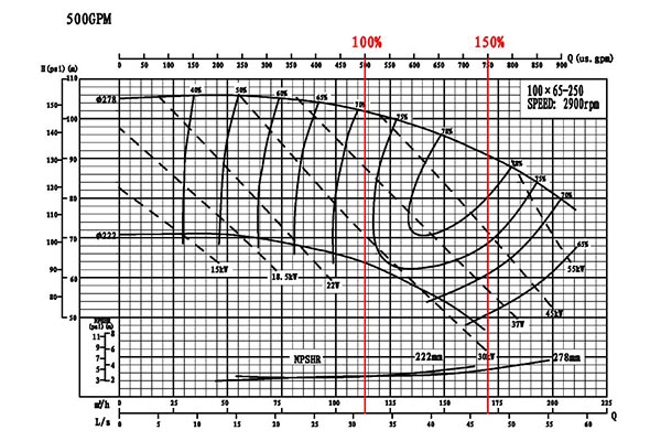
A pump performance curve is a graphical representation of the head generated by a specific pump model at rates of flow from zero to maximum at a given operating speed.
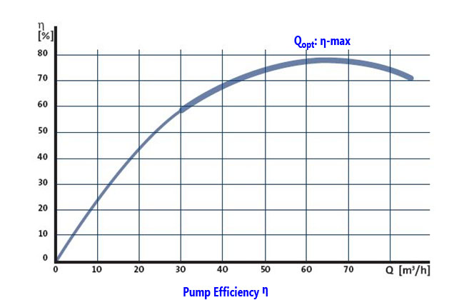
The efficiency curve shows pump efficiency at various flow rates. The flow rate where efficiency is at a maximum is called the pump’s best efficiency point (BEP). BEP is an important operating point that is further described later in this section.
The pump input power curve shows the amount of input power required for different flow rates. Pp can be determined by the following equation where Q is flow in
Pump input power can also be determined if the amount of power absorbed by the fluid and efficiency are known by rearranging the equation shown for the efficiency curve:
The final curve typically shown on a pump performance chart is the NPSHr for different flow rates. NPSHr is the minimum NPSH needed to achieve the specified performance at the specified flow rate, speed, and pumped liquid. NPSHr is further defined in Pump Principles.
A pump’s best efficiency point is defined as the flow rate and head at which the pump efficiency is the maximum at a given speed and impeller diameter. Typically, a pump is specified to have its duty point, or designed operating point, at BEP. At BEP, a pump will have low vibration and noise when compared to other operating points. Also, there is minimum recirculation within the impeller and shockless entry into the impeller. Shockless entry is when the flow entering the impeller matches the angle of the impeller vanes at entry.
The preferred operating region (POR) is a range of rates of flow to either side of the BEP within which the hydraulic efficiency and the operational reliability of the pump are not substantially degraded. Flow induced vibrations and internal hydraulic loading is low in this region. Depending on the specific speed of the pump, which is further defined in the pump principles section, the POR can be anywhere from 90-110% of BEP flow to 70-120% of BEP flow.
The AOR is the flow range at the rated speed with the impeller supplied in which the pump may be allowed to operate, as limited by cavitation, heating, vibration, noise, shaft deflection, fatigue, and other similar criteria. It is the flow range at which the pump can be run with acceptable service life. The pump manufacturer should be consulted to define this region. Typically, operating intermittently within this region does not cause issues over the life of the pump. The graph above shows the various operating regions and the types of issues that can occur when operating outside of the POR and AOR.
These points are important during manufacturer testing to fully define the shape of the pump curve. They are the furthest points to the left and right on the curve. Shut-off is the condition of zero flow rate where no liquid is flowing through the pump, but the pump is primed and running. Operating at this point for more than a few seconds can cause serious mechanical issues. Pump Runout is the point at which flow is at a maximum. Operating at this flow can cause cavitation, vibration and, in some pumps, overloading of the driver. These points are to be avoided when operating pumps.
Under the assumption that changing speed or impeller diameter of a pump maintains the same efficiencies, the Affinity Rules show the relationships between pump parameters (flow, pressure/head, power) and pump charactereistics (speed and impeller size) or a change in impeller size while maintaining a constant speed.
Part 1 of the affinity rules is ideal for instances where you have a Variable Frequency Drive attached to a pump motor. The VFD will reduce or increase the pump speed therefore allowing it to operate at a multitude of operating conditions. Part 2 is essential in calculating the new pump characteristics after impeller trimming which is the reduction of the impeller diameter.
Two or more pumps in a system can be placed either in parallel or in series. In parallel, a system consists of two or more pumps that are configured such that each draw from the same suction reservoir, wet well, or header, and each discharge to the same discharge reservoir or header. In series, a system consists of two or more pumps that are configured such that the discharge of one pump feeds the suction of a subsequent pump.
Pumps operating in parallel allow the pumping system to deliver greater flows than is possible with just one such pump. To determine the composite pump curve of two or more pumps operating in parallel, at each head value, the flowrate of each pump must be added together to obtain the composite flowrate.
The amount of increased flow that occurs within the system depends on both the shape of the system curve and shape of the pump curves. The composite pump curve intersects the system curve at different operating points yielding different flowrates. As more pumps are called to operate, the flow will increase accordingly:
It should be noted, however, that unless the system curve is completely flat (which means friction and other dynamic losses are negligible), bringing a second pump on-line does not double the flow rate. The increased flow will be something less than double. How much less depends on the steepness of the system curve.
While pumps placed in parallel provide greater flow capabilities at the same head as one pump operating individually, pumps placed in series provide greater head capabilities at the same flowrate.
A composite pump curve representing pumps in series can be generated by adding the individual head values of the pumps for a given flow. Plotting this sum at various flow values will yield a composite pump curve for the group of pumps. Figure 3 shows a composite pump curve for two and three identically sized pumps operating in series:
Pumps operating in series allow the pumping system to deliver greater heads than is possible with just one such pump. This allows a pump station to be designed to satisfy systems that require large discharge pressures that may not be practical with one pump. Where certain applications require, it may also allow a pump station to address a wide variation in system pressures by staging the number of operating pumps. Figure 4 shows how applying a configuration with pumps in series to a system with a steep system curve may allow the pumps to address different head requirements so long as inter-stage discharge piping is configured to permit so.
A booster pump is designed to operate at 1800 GPM and 135 ft., with a speed of 1740 RPM. Due to fluctuating flows the booster pump is equipped with a Variable Frequency Drive which reduces the pump speed by 10% during low flow conditions. Using the pump curve below and the affinity rules, generate the pump curve for low flow conditions and the new pumping conditions.

Hydraulic pumps are mechanisms in hydraulic systems that move hydraulic fluid from point to point initiating the production of hydraulic power. Hydraulic pumps are sometimes incorrectly referred to as “hydrolic” pumps.
They are an important device overall in the hydraulics field, a special kind of power transmission which controls the energy which moving fluids transmit while under pressure and change into mechanical energy. Other kinds of pumps utilized to transmit hydraulic fluids could also be referred to as hydraulic pumps. There is a wide range of contexts in which hydraulic systems are applied, hence they are very important in many commercial, industrial, and consumer utilities.
“Power transmission” alludes to the complete procedure of technologically changing energy into a beneficial form for practical applications. Mechanical power, electrical power, and fluid power are the three major branches that make up the power transmission field. Fluid power covers the usage of moving gas and moving fluids for the transmission of power. Hydraulics are then considered as a sub category of fluid power that focuses on fluid use in opposition to gas use. The other fluid power field is known as pneumatics and it’s focused on the storage and release of energy with compressed gas.
"Pascal"s Law" applies to confined liquids. Thus, in order for liquids to act hydraulically, they must be contained within a system. A hydraulic power pack or hydraulic power unit is a confined mechanical system that utilizes liquid hydraulically. Despite the fact that specific operating systems vary, all hydraulic power units share the same basic components. A reservoir, valves, a piping/tubing system, a pump, and actuators are examples of these components. Similarly, despite their versatility and adaptability, these mechanisms work together in related operating processes at the heart of all hydraulic power packs.
The hydraulic reservoir"s function is to hold a volume of liquid, transfer heat from the system, permit solid pollutants to settle, and aid in releasing moisture and air from the liquid.
Mechanical energy is changed to hydraulic energy by the hydraulic pump. This is accomplished through the movement of liquid, which serves as the transmission medium. All hydraulic pumps operate on the same basic principle of dispensing fluid volume against a resistive load or pressure.
Hydraulic valves are utilized to start, stop, and direct liquid flow in a system. Hydraulic valves are made of spools or poppets and can be actuated hydraulically, pneumatically, manually, electrically, or mechanically.
The end result of Pascal"s law is hydraulic actuators. This is the point at which hydraulic energy is transformed back to mechanical energy. This can be accomplished by using a hydraulic cylinder to transform hydraulic energy into linear movement and work or a hydraulic motor to transform hydraulic energy into rotational motion and work. Hydraulic motors and hydraulic cylinders, like hydraulic pumps, have various subtypes, each meant for specific design use.
The essence of hydraulics can be found in a fundamental physical fact: fluids are incompressible. (As a result, fluids more closely resemble solids than compressible gasses) The incompressible essence of fluid allows it to transfer force and speed very efficiently. This fact is summed up by a variant of "Pascal"s Principle," which states that virtually all pressure enforced on any part of a fluid is transferred to every other part of the fluid. This scientific principle states, in other words, that pressure applied to a fluid transmits equally in all directions.
Furthermore, the force transferred through a fluid has the ability to multiply as it moves. In a slightly more abstract sense, because fluids are incompressible, pressurized fluids should keep a consistent pressure just as they move. Pressure is defined mathematically as a force acting per particular area unit (P = F/A). A simplified version of this equation shows that force is the product of area and pressure (F = P x A). Thus, by varying the size or area of various parts inside a hydraulic system, the force acting inside the pump can be adjusted accordingly (to either greater or lesser). The need for pressure to remain constant is what causes force and area to mirror each other (on the basis of either shrinking or growing). A hydraulic system with a piston five times larger than a second piston can demonstrate this force-area relationship. When a force (e.g., 50lbs) is exerted on the smaller piston, it is multiplied by five (e.g., 250 lbs) and transmitted to the larger piston via the hydraulic system.
Hydraulics is built on fluids’ chemical properties and the physical relationship between pressure, area, and force. Overall, hydraulic applications allow human operators to generate and exert immense mechanical force with little to no physical effort. Within hydraulic systems, both oil and water are used to transmit power. The use of oil, on the other hand, is far more common, owing in part to its extremely incompressible nature.
Pressure relief valves prevent excess pressure by regulating the actuators’ output and redirecting liquid back to the reservoir when necessary. Directional control valves are used to change the size and direction of hydraulic fluid flow.
While hydraulic power transmission is remarkably useful in a wide range of professional applications, relying solely on one type of power transmission is generally unwise. On the contrary, the most efficient strategy is to combine a wide range of power transmissions (pneumatic, hydraulic, mechanical, and electrical). As a result, hydraulic systems must be carefully embedded into an overall power transmission strategy for the specific commercial application. It is necessary to invest in locating trustworthy and skilled hydraulic manufacturers/suppliers who can aid in the development and implementation of an overall hydraulic strategy.
The intended use of a hydraulic pump must be considered when selecting a specific type. This is significant because some pumps may only perform one function, whereas others allow for greater flexibility.
The pump"s material composition must also be considered in the application context. The cylinders, pistons, and gears are frequently made of long-lasting materials like aluminum, stainless steel, or steel that can withstand the continuous wear of repeated pumping. The materials must be able to withstand not only the process but also the hydraulic fluids. Composite fluids frequently contain oils, polyalkylene glycols, esters, butanol, and corrosion inhibitors (though water is used in some instances). The operating temperature, flash point, and viscosity of these fluids differ.
In addition to material, manufacturers must compare hydraulic pump operating specifications to make sure that intended utilization does not exceed pump abilities. The many variables in hydraulic pump functionality include maximum operating pressure, continuous operating pressure, horsepower, operating speed, power source, pump weight, and maximum fluid flow. Standard measurements like length, rod extension, and diameter should be compared as well. Because hydraulic pumps are used in lifts, cranes, motors, and other heavy machinery, they must meet strict operating specifications.
It is critical to recall that the overall power generated by any hydraulic drive system is influenced by various inefficiencies that must be considered in order to get the most out of the system. The presence of air bubbles within a hydraulic drive, for example, is known for changing the direction of the energy flow inside the system (since energy is wasted on the way to the actuators on bubble compression). Using a hydraulic drive system requires identifying shortfalls and selecting the best parts to mitigate their effects. A hydraulic pump is the "generator" side of a hydraulic system that initiates the hydraulic procedure (as opposed to the "actuator" side that completes the hydraulic procedure). Regardless of disparities, all hydraulic pumps are responsible for displacing liquid volume and transporting it to the actuator(s) from the reservoir via the tubing system. Some form of internal combustion system typically powers pumps.
While the operation of hydraulic pumps is normally the same, these mechanisms can be split into basic categories. There are two types of hydraulic pumps to consider: gear pumps and piston pumps. Radial and axial piston pumps are types of piston pumps. Axial pumps produce linear motion, whereas radial pumps can produce rotary motion. The gear pump category is further subdivided into external gear pumps and internal gear pumps.
Each type of hydraulic pump, regardless of piston or gear, is either double-action or single-action. Single-action pumps can only pull, push, or lift in one direction, while double-action pumps can pull, push, or lift in multiple directions.
Vane pumps are positive displacement pumps that maintain a constant flow rate under varying pressures. It is a pump that self-primes. It is referred to as a "vane pump" because the effect of the vane pressurizes the liquid.
This pump has a variable number of vanes mounted onto a rotor that rotates within the cavity. These vanes may be variable in length and tensioned to maintain contact with the wall while the pump draws power. The pump also features a pressure relief valve, which prevents pressure rise inside the pump from damaging it.
Internal gear pumps and external gear pumps are the two main types of hydraulic gear pumps. Pumps with external gears have two spur gears, the spurs of which are all externally arranged. Internal gear pumps also feature two spur gears, and the spurs of both gears are internally arranged, with one gear spinning around inside the other.
Both types of gear pumps deliver a consistent amount of liquid with each spinning of the gears. Hydraulic gear pumps are popular due to their versatility, effectiveness, and fairly simple design. Furthermore, because they are obtainable in a variety of configurations, they can be used in a wide range of consumer, industrial, and commercial product contexts.
Hydraulic ram pumps are cyclic machines that use water power, also referred to as hydropower, to transport water to a higher level than its original source. This hydraulic pump type is powered solely by the momentum of moving or falling water.
Ram pumps are a common type of hydraulic pump, especially among other types of hydraulic water pumps. Hydraulic ram pumps are utilized to move the water in the waste management, agricultural, sewage, plumbing, manufacturing, and engineering industries, though only about ten percent of the water utilized to run the pump gets to the planned end point.
Despite this disadvantage, using hydropower instead of an external energy source to power this kind of pump makes it a prominent choice in developing countries where the availability of the fuel and electricity required to energize motorized pumps is limited. The use of hydropower also reduces energy consumption for industrial factories and plants significantly. Having only two moving parts is another advantage of the hydraulic ram, making installation fairly simple in areas with free falling or flowing water. The water amount and the rate at which it falls have an important effect on the pump"s success. It is critical to keep this in mind when choosing a location for a pump and a water source. Length, size, diameter, minimum and maximum flow rates, and speed of operation are all important factors to consider.
Hydraulic water pumps are machines that move water from one location to another. Because water pumps are used in so many different applications, there are numerous hydraulic water pump variations.
Water pumps are useful in a variety of situations. Hydraulic pumps can be used to direct water where it is needed in industry, where water is often an ingredient in an industrial process or product. Water pumps are essential in supplying water to people in homes, particularly in rural residences that are not linked to a large sewage circuit. Water pumps are required in commercial settings to transport water to the upper floors of high rise buildings. Hydraulic water pumps in all of these situations could be powered by fuel, electricity, or even by hand, as is the situation with hydraulic hand pumps.
Water pumps in developed economies are typically automated and powered by electricity. Alternative pumping tools are frequently used in developing economies where dependable and cost effective sources of electricity and fuel are scarce. Hydraulic ram pumps, for example, can deliver water to remote locations without the use of electricity or fuel. These pumps rely solely on a moving stream of water’s force and a properly configured number of valves, tubes, and compression chambers.
Electric hydraulic pumps are hydraulic liquid transmission machines that use electricity to operate. They are frequently used to transfer hydraulic liquid from a reservoir to an actuator, like a hydraulic cylinder. These actuation mechanisms are an essential component of a wide range of hydraulic machinery.
There are several different types of hydraulic pumps, but the defining feature of each type is the use of pressurized fluids to accomplish a job. The natural characteristics of water, for example, are harnessed in the particular instance of hydraulic water pumps to transport water from one location to another. Hydraulic gear pumps and hydraulic piston pumps work in the same way to help actuate the motion of a piston in a mechanical system.
Despite the fact that there are numerous varieties of each of these pump mechanisms, all of them are powered by electricity. In such instances, an electric current flows through the motor, which turns impellers or other devices inside the pump system to create pressure differences; these differential pressure levels enable fluids to flow through the pump. Pump systems of this type can be utilized to direct hydraulic liquid to industrial machines such as commercial equipment like elevators or excavators.
Hydraulic hand pumps are fluid transmission machines that utilize the mechanical force generated by a manually operated actuator. A manually operated actuator could be a lever, a toggle, a handle, or any of a variety of other parts. Hydraulic hand pumps are utilized for hydraulic fluid distribution, water pumping, and various other applications.
Hydraulic hand pumps may be utilized for a variety of tasks, including hydraulic liquid direction to circuits in helicopters and other aircraft, instrument calibration, and piston actuation in hydraulic cylinders. Hydraulic hand pumps of this type use manual power to put hydraulic fluids under pressure. They can be utilized to test the pressure in a variety of devices such as hoses, pipes, valves, sprinklers, and heat exchangers systems. Hand pumps are extraordinarily simple to use.
Each hydraulic hand pump has a lever or other actuation handle linked to the pump that, when pulled and pushed, causes the hydraulic liquid in the pump"s system to be depressurized or pressurized. This action, in the instance of a hydraulic machine, provides power to the devices to which the pump is attached. The actuation of a water pump causes the liquid to be pulled from its source and transferred to another location. Hydraulic hand pumps will remain relevant as long as hydraulics are used in the commerce industry, owing to their simplicity and easy usage.
12V hydraulic pumps are hydraulic power devices that operate on 12 volts DC supplied by a battery or motor. These are specially designed processes that, like all hydraulic pumps, are applied in commercial, industrial, and consumer places to convert kinetic energy into beneficial mechanical energy through pressurized viscous liquids. This converted energy is put to use in a variety of industries.
Hydraulic pumps are commonly used to pull, push, and lift heavy loads in motorized and vehicle machines. Hydraulic water pumps may also be powered by 12V batteries and are used to move water out of or into the desired location. These electric hydraulic pumps are common since they run on small batteries, allowing for ease of portability. Such portability is sometimes required in waste removal systems and vehiclies. In addition to portable and compact models, options include variable amp hour productions, rechargeable battery pumps, and variable weights.
While non rechargeable alkaline 12V hydraulic pumps are used, rechargeable ones are much more common because they enable a continuous flow. More considerations include minimum discharge flow, maximum discharge pressure, discharge size, and inlet size. As 12V batteries are able to pump up to 150 feet from the ground, it is imperative to choose the right pump for a given use.
Air hydraulic pumps are hydraulic power devices that use compressed air to stimulate a pump mechanism, generating useful energy from a pressurized liquid. These devices are also known as pneumatic hydraulic pumps and are applied in a variety of industries to assist in the lifting of heavy loads and transportation of materials with minimal initial force.
Air pumps, like all hydraulic pumps, begin with the same components. The hydraulic liquids, which are typically oil or water-based composites, require the use of a reservoir. The fluid is moved from the storage tank to the hydraulic cylinder via hoses or tubes connected to this reservoir. The hydraulic cylinder houses a piston system and two valves. A hydraulic fluid intake valve allows hydraulic liquid to enter and then traps it by closing. The discharge valve is the point at which the high pressure fluid stream is released. Air hydraulic pumps have a linked air cylinder in addition to the hydraulic cylinder enclosing one end of the piston.
The protruding end of the piston is acted upon by a compressed air compressor or air in the cylinder. When the air cylinder is empty, a spring system in the hydraulic cylinder pushes the piston out. This makes a vacuum, which sucks fluid from the reservoir into the hydraulic cylinder. When the air compressor is under pressure, it engages the piston and pushes it deeper into the hydraulic cylinder and compresses the liquids. This pumping action is repeated until the hydraulic cylinder pressure is high enough to forcibly push fluid out through the discharge check valve. In some instances, this is connected to a nozzle and hoses, with the important part being the pressurized stream. Other uses apply the energy of this stream to pull, lift, and push heavy loads.
Hydraulic piston pumps transfer hydraulic liquids through a cylinder using plunger-like equipment to successfully raise the pressure for a machine, enabling it to pull, lift, and push heavy loads. This type of hydraulic pump is the power source for heavy-duty machines like excavators, backhoes, loaders, diggers, and cranes. Piston pumps are used in a variety of industries, including automotive, aeronautics, power generation, military, marine, and manufacturing, to mention a few.
Hydraulic piston pumps are common due to their capability to enhance energy usage productivity. A hydraulic hand pump energized by a hand or foot pedal can convert a force of 4.5 pounds into a load-moving force of 100 pounds. Electric hydraulic pumps can attain pressure reaching 4,000 PSI. Because capacities vary so much, the desired usage pump must be carefully considered. Several other factors must also be considered. Standard and custom configurations of operating speeds, task-specific power sources, pump weights, and maximum fluid flows are widely available. Measurements such as rod extension length, diameter, width, and height should also be considered, particularly when a hydraulic piston pump is to be installed in place of a current hydraulic piston pump.
Hydraulic clutch pumps are mechanisms that include a clutch assembly and a pump that enables the user to apply the necessary pressure to disengage or engage the clutch mechanism. Hydraulic clutches are crafted to either link two shafts and lock them together to rotate at the same speed or detach the shafts and allow them to rotate at different speeds as needed to decelerate or shift gears.
Hydraulic pumps change hydraulic energy to mechanical energy. Hydraulic pumps are particularly designed machines utilized in commercial, industrial, and residential areas to generate useful energy from different viscous liquids pressurization. Hydraulic pumps are exceptionally simple yet effective machines for moving fluids. "Hydraulic" is actually often misspelled as "Hydralic". Hydraulic pumps depend on the energy provided by hydraulic cylinders to power different machines and mechanisms.
There are several different types of hydraulic pumps, and all hydraulic pumps can be split into two primary categories. The first category includes hydraulic pumps that function without the assistance of auxiliary power sources such as electric motors and gas. These hydraulic pump types can use the kinetic energy of a fluid to transfer it from one location to another. These pumps are commonly called ram pumps. Hydraulic hand pumps are never regarded as ram pumps, despite the fact that their operating principles are similar.
The construction, excavation, automotive manufacturing, agriculture, manufacturing, and defense contracting industries are just a few examples of operations that apply hydraulics power in normal, daily procedures. Since hydraulics usage is so prevalent, hydraulic pumps are unsurprisingly used in a wide range of machines and industries. Pumps serve the same basic function in all contexts where hydraulic machinery is used: they transport hydraulic fluid from one location to another in order to generate hydraulic energy and pressure (together with the actuators).
Elevators, automotive brakes, automotive lifts, cranes, airplane flaps, shock absorbers, log splitters, motorboat steering systems, garage jacks and other products use hydraulic pumps. The most common application of hydraulic pumps in construction sites is in big hydraulic machines and different types of "off-highway" equipment such as excavators, dumpers, diggers, and so on. Hydraulic systems are used in other settings, such as offshore work areas and factories, to power heavy machinery, cut and bend material, move heavy equipment, and so on.
Fluid’s incompressible nature in hydraulic systems allows an operator to make and apply mechanical power in an effective and efficient way. Practically all force created in a hydraulic system is applied to the intended target.
Because of the relationship between area, pressure, and force (F = P x A), modifying the force of a hydraulic system is as simple as changing the size of its components.
Hydraulic systems can transfer energy on an equal level with many mechanical and electrical systems while being significantly simpler in general. A hydraulic system, for example, can easily generate linear motion. On the contrary, most electrical and mechanical power systems need an intermediate mechanical step to convert rotational motion to linear motion.
Hydraulic systems are typically smaller than their mechanical and electrical counterparts while producing equivalents amounts of power, providing the benefit of saving physical space.
Hydraulic systems can be used in a wide range of physical settings due to their basic design (a pump attached to actuators via some kind of piping system). Hydraulic systems could also be utilized in environments where electrical systems would be impractical (for example underwater).
By removing electrical safety hazards, using hydraulic systems instead of electrical power transmission improves relative safety (for example explosions, electric shock).
The amount of power that hydraulic pumps can generate is a significant, distinct advantage. In certain cases, a hydraulic pump could generate ten times the power of an electrical counterpart. Some hydraulic pumps (for example, piston pumps) cost more than the ordinary hydraulic component. These drawbacks, however, can be mitigated by the pump"s power and efficiency. Despite their relatively high cost, piston pumps are treasured for their strength and capability to transmit very viscous fluids.
Handling hydraulic liquids is messy, and repairing leaks in a hydraulic pump can be difficult. Hydraulic liquid that leaks in hot areas may catch fire. Hydraulic lines that burst may cause serious injuries. Hydraulic liquids are corrosive as well, though some are less so than others. Hydraulic systems need frequent and intense maintenance. Parts with a high factor of precision are frequently required in systems. If the power is very high and the pipeline cannot handle the power transferred by the liquid, the high pressure received by the liquid may also cause work accidents.
Even though hydraulic systems are less complex than electrical or mechanical systems, they are still complex systems that should be handled with caution. Avoiding physical contact with hydraulic systems is an essential safety precaution when engaging with them. Even when a hydraulic machine is not in use, active liquid pressure within the system can be a hazard.
Inadequate pumps can cause mechanical failure in the place of work that can have serious and costly consequences. Although pump failure has historically been unpredictable, new diagnostic technology continues to improve on detecting methods that previously relied solely on vibration signals. Measuring discharge pressures enables manufacturers to forecast pump wear more accurately. Discharge sensors are simple to integrate into existing systems, increasing the hydraulic pump"s safety and versatility.
Hydraulic pumps are devices in hydraulic systems that move hydraulic fluid from point to point, initiating hydraulic power production. They are an important device overall in the hydraulics field, a special kind of power transmission that controls the energy which moving fluids transmit while under pressure and change into mechanical energy. Hydraulic pumps are divided into two categories namely gear pumps and piston pumps. Radial and axial piston pumps are types of piston pumps. Axial pumps produce linear motion, whereas radial pumps can produce rotary motion. The construction, excavation, automotive manufacturing, agriculture, manufacturing, and defense contracting industries are just a few examples of operations that apply hydraulics power in normal, daily procedures.

Despite recent advances in predictive maintenance technologies, the maintenance professional’s ability to determine the remaining bearing life of a pump or motor, with a high degree of accuracy, remains elusive.
Deteriorating efficiency on the other hand is easy to detect. Because it typically shows itself through increased cycle times. In other words, the machine slows down. When this occurs, quantification of the efficiency loss is not always necessary. Reason being, if the machine slows to the point where its cycle time in unacceptably slow, the pump or motor is changed out. End of story.
In certain situations however, it can be helpful, even necessary, to quantify the pump or motor’s actual efficiency and compare it to the component’s native efficiency. And for this, an understanding of hydraulic pump and motor efficiency ratings is essential.
There are three categories of efficiency used to describe hydraulic pumps (and motors). Volumetric efficiency, mechanical/hydraulic efficiency and overall efficiency.
Volumetric efficiency is determined by dividing the actual flow delivered by a pump at a given pressure by its theoretical flow. Theoretical flow is calculated by multiplying the pump’s displacement per revolution by its driven speed. So if the pump has a displacement of 100 cc/rev and is being driven at 1000 RPM its theoretical flow is 100 liters/minute.
Actual flow has to be measured using a flow meter. If when tested, the above pump had an actual flow of 90 liters/minute at 207 bar (3000 PSI), we can say the pump has a volumetric efficiency of 90% at 207 bar (90 / 100 x 100 = 90%).
It’s volumetric efficiency we use most in the field to determine the condition of a hydraulic pump – based on its increase in internal leakage through wear or damage. But without reference to theoretical flow, the actual flow measured by the flow meter would be meaningless.
A pump’s mechanical/hydraulic efficiency is determined by dividing the theoretical torque required to drive it by the actual torque required to drive it. A mechanical/hydraulic efficiency of 100% would mean if the pump was delivering flow at zero pressure, no force or torque would be required to drive it. Intuitively, we know this is not possible – due to mechanical and fluid friction.
Like theoretical flow, theoretical drive torque can be calculated. For the above pump, in SI units: 100 cc/rev x 207 bar / 20 x pi = 329 Newton meters. But like actual flow, actual drive torque must be measured and this requires the use of a dynamometer. Not something we can-or need-to do in the field. For the purposes of this example though, let’s assume the actual drive torque was 360 Nm. Mechanical/hydraulic efficiency would be 91% (329 / 360 x 100 = 91%).
Overall efficiency is simply the product of volumetric and mechanical/hydraulic efficiency. So continuing with the above example, the overall efficiency of the pump is 0.9 x 0.91 x 100 = 82%. Typical overall efficiencies for different types of hydraulic pumps are shown in the table below (


 8613371530291