
typical hydraulic pump efficiency for sale
Gear pumps have very few moving parts. They consist of two intermeshing gears. These pumps have a constant flow rate. They operate at pressures generally between 50 and 210 bar. Gear pumps operate at the highest speeds of any pumps at up to 3000-6000 rpm.
In an external-gear pump, only one of the gear wheels, the drive gear, is connected to the drive. The other gear wheel, the driven gear, rotates in the opposite direction, so that the teeth of the rotating gear wheels interlock.
There are also double external-gear pumps, which combine two gear pumps driven by the same coupling shaft. A double external-gear pump has the advantage of supplying two independent hydraulic circuits, and also provides more flow to one circuit.

The goal of a hydraulic pump is to move hydraulic fluid through a hydraulic system, acting much like the beating heart of the system. There are two things that all hydraulic pumps have in common: (1) they provide hydraulic flow to other components (e.g., rams, hydraulic motors, cylinder) within a hydraulic system, and (2) they produce flow which in turn generates pressure when there is a resistance to flow. In addition, most hydraulic pumps are motor-driven and include a pressure relief valve as a type of overpressure protection. The three most common types of hydraulic pumps currently in use are gear, piston, and vane pumps.
In a gear pump, hydraulic fluid is trapped between the body of the pump and the areas between the teeth of the pump’s two meshing gears. The driveshaft is used to power one gear while the other remains idle until it meshes with the driving gear. These pumps are what is known as fixed displacement or positive displacement because each rotation of the shaft displaces the same amount of hydraulic fluid at the same pressure. There are two basic types of gear pumps, external and internal, which will be discussed in a moment.
Gear pumps are compact, making them ideal for applications that involve limited space. They are also simple in design, making them easier to repair and maintain. Note that gear pumps usually exhibit the highest efficiency when running at their maximum speed. In general, external gear pumps can produce higher levels of pressure (up to 3,000 psi) and greater throughput than vane pumps.
External gear pumps are often found in close-coupled designs where the gear pump and the hydraulic motor share the same mounting and the same shaft. In an external gear pump, fluid flow occurs around the outside of a pair of meshed external spur gears. The hydraulic fluid moves between the housing of the pump and the gears to create the alternating suction and discharge needed for fluid flow.
External gear pumps can provide very high pressures (up to 3,000 psi), operate at high speeds (3,000 rpm), and run more quietly than internal gear pumps. When gear pumps are designed to handle even higher pressures and speeds, however, they will be very noisy and there may be special precautions that must be made.
External gear pumps are often used in powerlifting applications, as well as areas where electrical equipment would be either too bulky, inconvenient, or costly. External gear pumps can also be found on some agricultural and construction equipment to power their hydraulic systems.
In an internal gear pump, the meshing action of external and internal gears works with a crescent-shaped sector element to generate fluid flow. The outer gear has teeth pointing inwards and the inner gear has teeth pointing outward. As these gears rotate and come in and out of mesh, they create suction and discharge zones with the sector acting as a barrier between these zones. A gerotor is a special type of internal gear pump that eliminates the need for a sector element by using trochoidal gears to create suction and discharge zones.
Unlike external gear pumps, internal gear pumps are not meant for high-pressure applications; however, they do generate flow with very little pulsation present. They are not as widely used in hydraulics as external gear pumps; however, they are used with lube oils and fuel oils and work well for metering applications.
In a piston pump, reciprocating pistons are used to alternately generate suction and discharge. There are two different ways to categorize piston pumps: whether their piston is axially or radially mounted and whether their displacement is fixed or variable.
Piston pumps can handle higher pressures than gear or vane pumps even with comparable displacements, but they tend to be more expensive in terms of the initial cost. They are also more sensitive to contamination, but following strict hydraulic cleanliness guidelines and filtering any hydraulic fluid added to the system can address most contamination issues.
In an axial piston pump, sometimes called an inline axial pump, the pistons are aligned with the axis of the pump and arranged within a circular cylinder block. On one side of the cylinder block are the inlet and outlet ports, while an angled swashplate lies on the other side. As the cylinder block rotates, the pistons move in and out of the cylinder block, thus creating alternating suction and discharge of hydraulic fluid.
Axial piston pumps are ideal for high-pressure, high-volume applications and can often be found powering mission-critical hydraulic systems such as those of jet aircraft.
In a bent-axis piston pump (which many consider a subtype of the axial piston pump), the pump is made up of two sides that meet at an angle. On one side, the drive shaft turns the cylinder block that contains the pistons which match up to bores on the other side of the pump. As the cylinder block rotates, the distances between the pistons and the valving surface vary, thus achieving the necessary suction and discharge.
In a radial piston pump, the pistons lie perpendicular to the axis of the pump and are arranged radially like spokes on a wheel around an eccentrically placed cam. When the drive shaft rotates, the cam moves and pushes the spring-loaded pistons inward as it passes them. Each of these pistons has its own inlet and outlet ports that lead to a chamber. Within this chamber are valves that control the release and intake of hydraulic fluid.
In a fixed displacement pump, the amount of fluid discharged in each reciprocation is the same volume. However, in a variable displacement pump, a change to the angle of the adjustable swashplate can increase or reduce the volume of fluid discharged. This design allows you to vary system speed without having to change engine speed.
When the input shaft of a vane pump rotates, rigid vanes mounted on an eccentric rotor pick up hydraulic fluid and transport it to the outlet of the pump. The area between the vanes increases on the inlet side as hydraulic fluid is drawn inside the pump and decreases on the outlet side to expel the hydraulic fluid through the output port. Vane pumps can be either fixed or variable displacement, as discussed for piston pumps.
Vane pumps are used in utility vehicles (such as those with aerial ladders or buckets) but are not as common today, having been replaced by gear pumps. This does not mean, however, that they are not still in use. They are not designed to handle high pressures but they can generate a good vacuum and even run dry for short periods of time.
There are other key aspects to choosing the right hydraulic pump that goes beyond deciding what type is best adapted to your application. These pump characteristics include the following:
Selecting a pump can be very challenging, but a good place to start is looking at the type of pump that you need. Vane pumps have been largely replaced by compact, durable gear pumps, with external gear pumps working best for high pressure and operating speeds while internal gear pumps are able to generate flow with very little pulsation. However, vane pumps are still good for creating an effective vacuum and can run even when dry for short periods of time. Piston pumps in general are more powerful but, at the same time, more susceptible to contamination.
Whether the pump is needed for the rugged world of mining, the sterile world of food and beverage processing, or the mission-critical aerospace industry, MAC Hydraulics can assist you with selecting, installing, maintaining, and repairing the right pump to meet the needs of your hydraulic system. In the event of a breakdown, our highly skilled technicians can troubleshoot and repair your pump — no matter who the manufacturer happens to be. We also offer on-site services that include common repairs, preventative maintenance, lubrication, cleaning, pressure testing, and setting.

There are typically three types of hydraulic pump constructions found in mobile hydraulic applications. These include gear, piston, and vane; however, there are also clutch pumps, dump pumps, and pumps for refuse vehicles such as dry valve pumps and Muncie Power Products’ Live PakTM.
The hydraulic pump is the component of the hydraulic system that takes mechanical energy and converts it into fluid energy in the form of oil flow. This mechanical energy is taken from what is called the prime mover (a turning force) such as the power take-off or directly from the truck engine.
With each hydraulic pump, the pump will be of either a uni-rotational or bi-rotational design. As its name implies, a uni-rotational pump is designed to operate in one direction of shaft rotation. On the other hand, a bi-rotational pump has the ability to operate in either direction.
For truck-mounted hydraulic systems, the most common design in use is the gear pump. This design is characterized as having fewer moving parts, being easy to service, more tolerant of contamination than other designs and relatively inexpensive. Gear pumps are fixed displacement, also called positive displacement, pumps. This means the same volume of flow is produced with each rotation of the pump’s shaft. Gear pumps are rated in terms of the pump’s maximum pressure rating, cubic inch displacement and maximum input speed limitation.
Generally, gear pumps are used in open center hydraulic systems. Gear pumps trap oil in the areas between the teeth of the pump’s two gears and the body of the pump, transport it around the circumference of the gear cavity and then force it through the outlet port as the gears mesh. Behind the brass alloy thrust plates, or wear plates, a small amount of pressurized oil pushes the plates tightly against the gear ends to improve pump efficiency.
A cylinder block containing pistons that move in and out is housed within a piston pump. It’s the movement of these pistons that draw oil from the supply port and then force it through the outlet. The angle of the swash plate, which the slipper end of the piston rides against, determines the length of the piston’s stroke. While the swash plate remains stationary, the cylinder block, encompassing the pistons, rotates with the pump’s input shaft. The pump displacement is then determined by the total volume of the pump’s cylinders. Fixed and variable displacement designs are both available.
With a fixed displacement piston pump, the swash plate is nonadjustable. Its proportional output flow to input shaft speed is like that of a gear pump and like a gear pump, the fixed displacement piston pump is used within open center hydraulic systems.
As previously mentioned, piston pumps are also used within applications like snow and ice control where it may be desirable to vary system flow without varying engine speed. This is where the variable displacement piston pump comes into play – when the hydraulic flow requirements will vary based on operating conditions. Unlike the fixed displacement design, the swash plate is not fixed and its angle can be adjusted by a pressure signal from the directional valve via a compensator.
Vane pumps were, at one time, commonly used on utility vehicles such as aerial buckets and ladders. Today, the vane pump is not commonly found on these mobile (truck-mounted) hydraulic systems as gear pumps are more widely accepted and available.
Within a vane pump, as the input shaft rotates it causes oil to be picked up between the vanes of the pump which is then transported to the pump’s outlet side. This is similar to how gear pumps work, but there is one set of vanes – versus a pair of gears – on a rotating cartridge in the pump housing. As the area between the vanes decreases on the outlet side and increases on the inlet side of the pump, oil is drawn in through the supply port and expelled through the outlet as the vane cartridge rotates due to the change in area.
Input shaft rotates, causing oil to be picked up between the vanes of the pump which is then transported to pump outlet side as area between vanes decreases on outlet side and increases on inlet side to draw oil through supply port and expel though outlet as vane cartridge rotates
A clutch pump is a small displacement gear pump equipped with a belt-driven, electromagnetic clutch, much like that found on a car’s air conditioner compressor. It is engaged when the operator turns on a switch inside the truck cab. Clutch pumps are frequently used where a transmission power take-off aperture is not provided or is not easily accessible. Common applications include aerial bucket trucks, wreckers and hay spikes. As a general rule clutch pumps cannot be used where pump output flows are in excess of 15 GPM as the engine drive belt is subject to slipping under higher loads.
What separates this pump from the traditional gear pump is its built-in pressure relief assembly and an integral three-position, three-way directional control valve. The dump pump is unsuited for continuous-duty applications because of its narrow, internal paths and the subsequent likelihood of excessive heat generation.
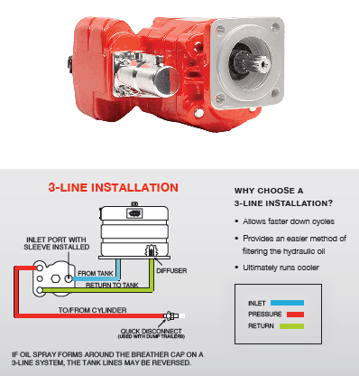
Dump pumps are often direct mounted to the power take-off; however, it is vital that the direct-coupled pumps be rigidly supported with an installer-supplied bracket to the transmission case with the pump’s weight at 70 lbs. With a dump pump, either a two- or three-line installation must be selected (two-line and three-line refer to the number of hoses used to plumb the pump); however, a dump pump can easily be converted from a two- to three-line installation. This is accomplished by inserting an inexpensive sleeve into the pump’s inlet port and uncapping the return port.
Many dump bodies can function adequately with a two-line installation if not left operating too long in neutral. When left operating in neutral for too long however, the most common dump pump failure occurs due to high temperatures. To prevent this failure, a three-line installation can be selected – which also provides additional benefits.
Pumps for refuse equipment include both dry valve and Live Pak pumps. Both conserve fuel while in the OFF mode, but have the ability to provide full flow when work is required. While both have designs based on that of standard gear pumps, the dry valve and Like Pak pumps incorporate additional, special valving.
Primarily used on refuse equipment, dry valve pumps are large displacement, front crankshaft-driven pumps. The dry valve pump encompasses a plunger-type valve in the pump inlet port. This special plunger-type valve restricts flow in the OFF mode and allows full flow in the ON mode. As a result, the horsepower draw is lowered, which saves fuel when the hydraulic system is not in use.
In the closed position, the dry valve allows just enough oil to pass through to maintain lubrication of the pump. This oil is then returned to the reservoir through a bleed valve and small return line. A bleed valve that is fully functioning is critical to the life of this type of pump, as pump failure induced by cavitation will result if the bleed valve becomes clogged by contaminates. Muncie Power Products also offer a butterfly-style dry valve, which eliminates the bleed valve requirement and allows for improved system efficiency.
It’s important to note that with the dry valve, wear plates and shaft seals differ from standard gear pumps. Trying to fit a standard gear pump to a dry valve likely will result in premature pump failure.
Encompasses plunger-type valve in the pump inlet port restricting flow in OFF mode, but allows full flow in ON mode lowering horsepower draw to save fuel when not in use
Wear plates and shaft seals differ from standard gear pumps – trying to fit standard gear pump to dry valve likely will result in premature pump failure
Live Pak pumps are also primarily used on refuse equipment and are engine crankshaft driven; however, the inlet on a Live Pak pump is not outfitted with a shut-off valve. With a Live Pak pump, the outlet incorporates a flow limiting valve. This is called a Live Pak valve. The valve acts as an unloading valve in OFF mode and a flow limiting valve in the ON mode. As a result, the hydraulic system speed is limited to keep within safe operating parameters.
Outlet incorporates flow limiting valve called Live Pak valve – acts as an unloading valve in OFF mode and flow limiting valve in ON mode restricting hydraulic system speed to keep within safe operating parameters

Editor"s Note: This is the first in a six-part series on centrifugal pump efficiency. For other articles in this series, clickCentrifugal Pump Efficiency series.
In this multi-part series, we will investigate several aspects of centrifugal pump efficiency. First, I will define efficiency and give some examples. Next, I will examine some of the design criteria that ultimately dictate the efficiency exhibited by a particular pump.
I will also try to make that somewhat nebulous quantity, known as specific speed, more meaningful. I will illustrate its effect on the shape of a pump’s performance curve and overall pump efficiency.
Next, I will explain the contributions of individual pump components to a pump’s overall efficiency and show why the combined efficiency of a pump and its driver is the product, not the average, of the two efficiencies.
How pump efficiency can be preserved by changing impeller speed rather than reducing it diameter will also be examined. Then I will compare the value of peak efficiency versus the breadth of efficiency over a range of flow. The discussion will end with the importance, or sometimes unimportance, of efficiency as it relates to a particular application or process.
When we speak of the efficiency of any machine, we are simply referring to how well it can convert one form of energy to another. If one unit of energy is supplied to a machine and its output, in the same units of measure, is one-half unit, its efficiency is 50 percent.
The efficiency of the typical automobile engine is around 20 percent. To put it another way, 80 percent of the heat energy in a gallon of gasoline does no useful work. Although gas mileage has increased somewhat over the years, that increase has as much to do with increased mechanical efficiency as increased engine efficiency itself.
In the pump industry, much of the work involves two extremely simple, yet efficient, machines—the centrifugal pump and the AC induction motor. The centrifugal pump converts mechanical energy into hydraulic energy (flow, velocity and pressure), and the AC motor converts electrical energy into mechanical energy.
Many medium and larger centrifugal pumps offer efficiencies of 75 to 93 percent and even the smaller ones usually fall into the 50 to 70 percent range. Large AC motors, on the other hand, approach an efficiency of 97 percent, and any motor—ten horsepower and above—can be designed to break the 90 percent barrier.
The overall efficiency of a centrifugal pump is simply the ratio of the water (output) power to the shaft (input) power and is illustrated by the equation below:
The constant (3,960) converts the product of flow and head (GPM-feet) into BHP. These equations predict that a pump that produces 100 GPM at 30 feet of head and requires 1 BHP will have an overall efficiency is 75.7 percent at that flow point. An extension of the second equation also allows the computation of the BHP required at any point on a pump’s performance curve if we know its hydraulic efficiency. I will show some examples of this later in this series.
The overall efficiency of a centrifugal pump is the product of three individual efficiencies—mechanical, volumetric and hydraulic. Mechanical efficiency includes losses in the bearing frame, stuffing box and mechanical seals. Volumetric efficiency includes losses due to leakage through the wear rings, balancing holes and vane clearances in the case of semi-open impellers. Hydraulic efficiency includes liquid friction and other losses in the volute and impeller.
Although mechanical and volumetric losses are important components, hydraulic efficiency is the largest factor. The centrifugal pump has a lot in common with the induction motor when it comes to the design phase. The commonality is that both have only two major components that can be modified by the designer. In the case of the motor, it is the rotor and the stator. For the centrifugal pump, it is the impeller and the volute (or diffuser). Let’s start our investigation of centrifugal pump efficiency with the impeller.
In the early days, that is exactly what pump designers did. Today, however, they can draw on years of experience and, at a minimum, find a suitable starting point for the design. That starting point is specific speed. Next month, we will investigate specific speed and how it can predict the performance of a particular impeller.
There are many great pump books available today, but one of the classics is now available as a free download at Google Books. Pumping Machinery was authored by Arthur M. Green, a professor of mechanical engineering at Rensselaer Polytechnic Institute and was published by John Wiley & Sons over 100 years ago. It begins with a comprehensive history of pumps and ends with a detailed review of centrifugal pumps and their advances over the previous twenty years. You will be impressed at the level of knowledge possessed by the author. The number of illustrations is amazing and accounts for a significant portion of its 725 pages. This one gets an A+ rating from me.
Studies reveal that efficiencies of industrial hydraulic systems range from <9% to 60% efficient, and average efficiency was 22%. So on average, the cost of wasted energy is $24.3 billion. Improving efficiency of industrial hydraulics by just an additional 10% would result in savings of approximately $3 billion per year.
Efficiency is the ratio of output power to input power. For example, if a hydraulic components and system can transmit 100 hp out for some work process, but because of inefficiencies in the system it requires 125 hp of input from a prime mover, then the hydraulic system is 80% efficient.
The good news is there are many opportunities to improve efficiency and garner substantial energy and cost savings. Start with an understanding of the system operation and by reviewing schematics. Ask yourself, what areas are inefficient in their use of energy during operation? The key is analyzing the design’s required output power versus input power.
Reservoirs. Beware of rules of thumb that result in sizing the reservoir too large. Standard practice is three times the pump flow. But the primary reason given is to remove heat, which is a myth. The reservoir is not an effective heat sink and requires an extremely large size to dissipate typical heat, unless duty cycle is low.
Prime movers. Review the current electric-motor design and decide if the return on investment for energy savings would justify replacing the current unit with a premium high-efficiency motor. And it may be better for overall operation of the system to retrofit with a variable-speed drive. Except for applications where the pump-motor combination runs continuously at a constant speed, a VFD can often quickly pay for itself with sizable energy savings.
The Energy Independence and Security Act of 2007 (EISA) raised to a premium level the mandatory minimum nominal full-load efficiency for general-purpose motors rated below 1,000 V and up to 200 hp. For example, the previous standard efficiency for a 10 hp motor was 86.7% and the new minimum efficiency level is 92.2%. Minimum efficiency for motors greater than 200 hp is 96%. However, keep in mind that a 1% increase in efficiency for a 100 hp motor will result in more cost savings than a 9% increase in efficiency of a 10 hp motor.
The flow source (pump).Depending on the design and operation, efficiency can vary significantly from one type of pump to another. Analyze the overall efficiency of the hydraulic pump and the control method used, and evaluate your ROI to determine if it is justified to change to a more-efficient system.
Analyze dwell times, if any exist, and determine how to minimize energy use during this time. Among the possibilities: add an accumulator, unload the pump, select a variable-speed drive, or upgrade the pump controls. Using RMS power calculations helps determine if the prime mover can be downsized, which will reduce overall energy consumption during dwell times. Also, analyze pump displacement and determine if it is properly sized for the energy demand.
Evaluate the fluid.Determine fluid requirements, for example the viscosity, based on the application and system components. Two areas that primarily impact pumps and motors are volumetric efficiency and hydromechanical efficiency. There is a viscosity range where fluid friction, mechanical friction and volumetric losses are minimized and optimal for hydraulic system performance. This is the viscosity range where the hydraulic system will operate most efficiently — the highest ratio of output power to input power.
A study published in Machinery Lubrication magazine showed that by using high Viscosity Index fluids, typical cost savings per vane pump in mobile hydraulic systems was approximately $400 per year. Mobil Corp. conducted a study on a typical ISO VG 46 fluid versus a high VI fluid at the same viscosity grade and showed efficiency improvements of 3 to 6% due to the fluid alone.
In-plant savings would be typically less as the temperature of fluids used in industrial systems is much more regulated and consistent, although during cold start-ups or high temperature operations, savings would be realized in industrial systems through high VI fluids.
Fluid conductor sizing.Pressure drop caused by frictional losses in fluid conductors is a significant source of wasted energy in a typical hydraulic system. Designers attempt to balance pressure drop against the cost of conductors and, in most cases, reduce the size of conductors to lower initial system cost without regard to total operating cost due to wasted energy.
So circuit designers should avoid extra fittings, sharp bends and undersized inner diameters of conductors — especially for pump inlets to avoid cavitation. In the pump inlet line, it is recommended that a straight length of at least 10 times the inner diameter of the fluid conductor be established directly prior to the pump inlet to allow for a transition back to laminar flow and minimize potential cavitation.
Undersized valves can also lead to increased energy loss due to throttling effects and friction (heat). Improperly sized pressure controls can have excessive pressure override which also results in energy waste and reduces efficiency.
Contamination control. To ensure a high-performing and reliable hydraulic system, engineers should determine the target cleanliness level, evaluate the contamination control system, and sample fluid regularly and look for evidence of oxidation.
Proper filtration and contamination control is essential for energy efficient systems. Improper contamination control leads to many consequences, none of them good. It results in increased component wear, with more internal leakage and wasted energy. It changes fluid viscosity which impacts efficiency as described previously.
Heat is also a contaminant, as it accelerates degradation (oxidation) of the fluid and impacts system efficiency. Lack of contamination control can result in valves partially opening and increasing throttling losses. Likewise, excessive air is another contaminant in the fluid, and it can affect heat transfer rates and damage pumps.
Actuator selection. Evaluate seal choice because internal friction results in energy loss. Different materials, types and designs can have a noticeable impact on dynamic seal performance and efficiency. Also evaluate the condition of internal seals, as damaged seals permit leakage which generates heat and wastes energy.
Look for the presence of a heat exchanger, and analyze its size compared to a typical unit based on size of the system. A cooler rated at higher than 30% of overall system horsepower could be indicator of energy inefficiencies that should be addressed.

Knowing how to right-size an electric motor for your hydraulic pump can help reduce energy consumption and increase operational efficiency. The key is to ensure the pump motor is operating at peak continuous load. But how can you know how much power is needed?
Before you can choose the correct electric motor, you must know how much horsepower (Hp) is required to drive the pump shaft. Generally, this is calculated by multiplying the flow capacity in gallons per minute (GPM) by the pressure in pounds per square inch (PSI). You then divide the resulting number by 1714 times the efficiency of the pump, for a formula that looks like this:
If you’re not sure how efficient your hydraulic pump is, it is advisable to use a common efficiency of about 85% (Multiplying 1714 x 0.85 = 1460 or 1500 if you round up). This work-around simplifies the formula to:
The above formula works in most applications with one notable exception: If the operating pressure of a pump is very low, the overall efficiency will be much lower than 85%. That’s because overall efficiency is equal to mechanical efficiency (internal mechanical friction) plus volumetric efficiency.
Internal friction is generally a fixed value, but volumetric efficiency changes depending on the pressure used. Low-pressure pumps have high volumetric efficiency because they are less susceptible to internal leakage. However, as the pressure goes up and internal fluids pass over work surfaces such as pistons, port plates, and lubrication points, the volumetric efficiency goes down and the amount of torque required to turn the pump for developing pressure goes up.
This variance makes it very important to know the efficiency of your pump if you’re using it at low pressure! Calculations that do not take low pressure into account will lead to a failed design.
If you calculate 20 GPM @ 300 PSI with an assumed overall efficiency of 89%, you would probably select a 5 Hp electric motor. However, if you calculate the same 20 GPM @ 300 PSI with the actual overall efficiency of 50%, you would know that you should be using a 7.5 Hp motor. In this example, making an assumption about the efficiency of your pump could result in installing a motor that is too large, driving up your overall operating cost.
There are many contributors to the overall efficiency of a hydraulic pump, and it pays to be as accurate as possible when choosing a motor. A best practice for proper sizing is to use published data from the pump vendor that shows actual input torque vs. pressure or overall efficiency vs pressure. Note that efficiency is also affected by RPM.
Identifying a right-sized motor for your hydraulic pump does not always ensure you are using the most efficient motor. Be sure to read Part 2 of this post to learn how RMS loading and Hp limiting can help you scale down the size of your electric motor to save money while maximizing efficiency.

Our submersible hydraulic water pump is more versatile and efficient than traditional electric pumps. These portable hydraulic water pumps utilize a highly efficient design to remove water quickly. Moreover, they can run dry and require no cooling while operating.
RGC offers Flow Dividers, allowing you to run RGC tools from an auxiliary power supply. We also offer additional supplies and accessories for our hydraulic water pumps, including hose whips, hydraulic hoses, and biodegradable hydraulic oil.
Questions about our hydraulic water pumps for sale? Reach out to us online by filling out our contact form, or call us at 800-831-5438. With over 75 years of experience in hydraulic tool manufacturing, we’re happy to help in any way we can. Our expert team will answer any questions and provide you with more information regarding our pump products and hydraulic tools.
The type of hydraulic pump you need depends on a variety of factors, including, but not limited to, the type of hydraulic fluid used in your machinery, operating pressure, application speed, and flow rate requirements.
Two of the most common pumps used in hydraulic equipment are piston pumps and gear pumps. This article will highlight everything you need to know about each pump, including its common uses and benefits.
A piston pump is a positive displacement pump that uses reciprocating motion to create rotation along an axis. Some piston pumps have variable displacement, while others have a fixed displacement design.
A hydraulic piston pump is capable of the highest pressure ratings and is commonly used to power heavy-duty lifts, presses, shovels, and other components.
The downside of piston pumps is that they are often more expensive (especially when compared to gear pumps). Still, their improved efficiency often makes them a better investment for long-term production.
Gear pumps use gears or cogs to transfer fluids. The cogs are tightly aligned to create suction as they draw liquid in and discharge it. The gears can be internal or external, depending on the application. Gear pumps are also positive displacement pumps, but they are always fixed displacement, so you would need separate pumps or valves to control the amount of displacement.
Gear pumps are known for being reliable and durable when they are well-maintained. Compared to piston pumps, they also don’t require as much maintenance and are typically more affordable. However, these pumps usually max out at 3000 PSI. While this is enough pressure to power some machinery, it may not have the power to operate large presses and other industrial equipment. A gear-style pump also lacks the ability to vary the displacement of your system.
Gear pumps are often used in low-pressure applications where dispensing high-viscosity liquids is required. They are typically used in the food and beverage, pulp and paper, and oil/chemical industries.
The primary difference between a gear pump and a piston pump is how they are designed. While both pumps need hydraulic fluid to generate mechanical power, a piston pump uses a piston to move liquid throughout the pump valves, while a gear pump uses cogs to move fluid throughout the pump.
Gear pumps are affordable for low-pressure applications (35 to 200 bar or 507 to 2900 PSI), while piston pumps are more efficient options for high-pressure applications. A piston pump is also a better option if you’re looking for a pump with a higher discharge rate. Lastly, a piston pump will provide the most efficiency if your application is high-speed.
Founded over 25 years ago. Panagon Systems specializes in remanufacturing cost-efficient obsolete or discontinued piston pumps, motors, and replacement components from brands like Vickers/Eaton, Caterpillar, and Rexroth. All pumps we manufacture are made in-house in the United States and are guaranteed to meet OEM specifications.
If you’re looking for cost-effective and timely pump replacement options, you’re looking for us.Contact us todayfor help in selecting the right pump for your application, or to request a product quote.

Hydraulic pumps come in different forms to accommodate a range of application requirements, from industrial die presses to heavy-duty off road equipment. One hydraulic system can vary greatly from another. For one system, a hydraulic piston pump may be the best solution, while a hydraulic gear pump may be better suited for a different one.
Powered by a hydraulic drive, a piston pump has a reciprocating positive displacement design to manage fluid flow. Pistons, or cylindrical elements within a cylinder block, create a vacuum, generated by a drive mechanism, that draws in fluid. The cylindrical chamber is pressurised by distributing energy into the fluid, compressing and forcing it towards the pump’s outlet.
Basic designs can generate about 4,000 psi, but pumps with up to 14,500 psi operating pressure are available. There are many different models that can displace a specific amount of fluid. Some allow you to adjust the displacement per revolution, which can make them more energy efficient. Piston pumps are relatively complex in design and expensive, but practical in energy-efficient applications that require high pressures and effective oil flow control.
A hydraulic gear pump is a lower-cost option, but it is quite durable, with many options available. The typical pressure rating is about 3,000 psi, but many displacement sizes and pressures can be found. Some gear pumps are rated as high as 4,500 psi, although additional valves will be needed in systems that require regular flow adjustments.
Gear pumps function by drawing fluid between their meshing gears. The adjacent gear teeth form chambers that are enclosed within the housing and pressure plates. A partial vacuum forms at the inlet where the gear teeth unmesh, allowing fluid to fill the space and be moved along the outer edge of the gears; as the gear teeth mesh again, fluid is forced out of the pump.
Both pumps use hydraulic fluid to transfer energy or generate mechanical force. Hydraulic piston pumps rely on reciprocating motion. Rotational forces are generated along an axis. Fixed and variable displacement pumps are available, as are different types, including axial, inline, bent-axis, plunger, and radial pumps, each with its own unique method of pushing fluid.
On the other hand, gear pumps move fluid via tightly aligned cogs that create suction to draw in and discharge fluid. Pumps with internal or external gears can be used, depending on the application requirements. Lobe, screw, and vane pumps are just some available types. A downside of using gear pumps is that additional devices are needed to control the desired amount of displacement, as they operate on fixed displacement only.
While gear pumps are available in a wide range of displacement sizes and pressures, and they suit various machinery applications, piston pumps offer the benefits of higher pressure ratings and are variable displacement and energy efficient. Rapid cooling means each pump is ready for the next operating cycle and can be serviced soon after shut-off.
Gear pumps typically don’t move more than 50 gallons per minute of fluid. On the other hand, some piston pumps can move hundreds of gallons per minute. Either one has advantages, depending on your hydraulic application.
Hydraulic pumps are available in different types, sizes, pressure ratings, and other specifications. It is important to choose the right pump for your hydraulic system. Gear pumps are suited for various types of machinery. Piston pumps are often found in oil field and agricultural applications, as well as in heavy-duty construction equipment. They are reliable and efficient, and they resist leakage at high speeds and pressures.
White House Products, Ltd. supplies, repairs, and maintains hydraulic gear pumps and hydraulic piston pumps from leading manufacturers. We can assist you in choosing a pump that meets your application requirements. Start browsing our catalog or register/login to view prices/availability and place an order. Contact us at +44 (0)1475 742500 for more information.

Even the best-performing hydraulic pumps from top hydraulic gear pump suppliers need to be replaced eventually. Because work and environmental conditions are different on every work site, it can be difficult to place an exact timeframe on how long a pump will last. In order to stay on top of the condition and remaining lifespan of hydraulic pumps, and hydraulic systems overall, it’s important to consider two things: 1) remaining seal life 2) how fast a pump’s efficiency is deteriorating.
Efficiency is the easier of these two criteria to keep track of. If a pump’s performance has been steadily deteriorating or has suddenly declined, then it is probably reaching the end of its lifespan and will need to be replaced to sustain a reliable hydraulic system. The easiest way to judge the deterioration in a pump’s performance is to monitor and compare cycle times (i.e., the speed at which the machine operates).
However, sometimes it is necessary to take exact measurements of a pump’s performance efficiency, which can be quantified by three different categories: volumetric efficiency, mechanical/hydraulic efficiency, and overall efficiency:
• Volumetric flow: Determined by dividing the actual flow delivered by a pump at a given pressure by its theoretical flow. Actual flow is measured using a flow meter. To calculate theoretical flow, multiply the pump’s displacement per revolution by its driven speed. The result will give you the volumetric efficiency at a particular pressure so it will be necessary to take these readings over a range of pressures as the pump may be very efficient at low pressure but very inefficient at higher pressures.
• Mechanical/hydraulic efficiency: Determined by dividing theoretical torque required to drive the pump by the actual torque required to drive the pump. Theoretical torque is measured in Newton meters. Measuring actual drive torque requires a dynamometer.
Volumetric efficiency helps assess the pump’s condition in the field. If there is wear or damage increasing internal leakage, this measurement can help identify whether pump maintenance is required. In addition to mechanical performance, overall efficiency helps determine if hydraulic pump replacement is necessary. To help calculate the drive power the pump requires at a given flow and pressure, you need to know its overall efficiency. If the drive power required increases or decreases, the pump is probably operating less efficiently.
A hydraulic pump system must be properly maintained to ensure it remains reliable, but there are other factors that impact reliability. These include temperature; a hydraulic pump is most stable in cooler temperatures. Overheated hydraulic oil will lose its lubricity and become oxidized, causing increased wear on metal parts and potentially hydraulic pump overheating. The ambient temperature of the operating environment needs to be considered as well and regulated using equipment such as forced-air coolers or a liquid-to-liquid cooler.
Any hydraulic pump installation requires a clean environment. Particle contamination is a common cause of equipment failure; high-pressure flow can impact particles in a way they ordinarily wouldn’t react. Therefore, specialized filtration systems are required, such as kidney-loop filtration systems that circulate oil through a filter to maintain a particulate-free flow. Water contamination is another threat; water intrusion and even the slightest amount of moisture and humidity can affect hydraulic fluid and components. Desiccant breathers, absorbent filters, and vacuum dehydrators may be used in a plant to control moisture levels.
For more information on maintaining hydraulic pumps and motors, or to order hydraulic pumps, and other hydraulic component supplies, contact White House Products Ltd. today at +44 (0) 1475-742500.

Calculation of preliminary cooler capacity: Heat dissipation from hydraulic oil tanks, valves, pipes and hydraulic components is less than a few percent in standard mobile equipment and the cooler capacity must include some margins. Minimum cooler capacity, Ecooler = 0.25Ediesel
At least 25% of the input power must be dissipated by the cooler when peak power is utilized for long periods. In normal case however, the peak power is used for only short periods, thus the actual cooler capacity required might be considerably less. The oil volume in the hydraulic tank is also acting as a heat accumulator when peak power is used.
The system efficiency is very much dependent on the type of hydraulic work tool equipment, the hydraulic pumps and motors used and power input to the hydraulics may vary considerably. Each circuit must be evaluated and the load cycle estimated. New or modified systems must always be tested in practical work, covering all possible load cycles.
How does a hydro gear pump work? A mechanical device known as a hydraulic pump transforms mechanical energy into hydraulic energy. It generates flow with enough force to counteract the load"s pressure. When activated, the hydraulic pump serves two purposes. The fluid is forced out of the tank by air pressure after which it is pumped through the pump inlet line thanks to the mechanical action of the pump, which first creates a vacuum at the pump inlet. Second, the fluid is moved by the pump"s mechanical action and pushed into the hydraulic system. Which hydraulic pumps come in the most popular varieties? Rotary pumps, gear pumps, and radial piston pumps are the three most popular types of hydraulic pumps. All are suitable for typical hydraulic applications, but piston designs for higher pressures are advised. Positive displacement pumps make up the majority of pumps used in hydraulic systems. This indicates that the same volume of fluid is displaced (delivered) throughout each revolution of the pumping element. Regardless of pressure variations, the supply volume every cycle remains roughly constant. Pumps with positive displacement can have fixed or variable displacement assemblies. A fixed displacement pump"s output stays consistent at a specific pump speed throughout each pumping cycle. The output of the variable volume pump is altered by altering the shape of the volume chamber Dosing pumps, also known as screw pumps, are perfect for usage in theatres and opera houses because of how quiet they are. Variable displacement pumps, on the other hand, are very helpful in circuits that use hydraulic actuators and need the ability for variable speed or return.
A positive displacement (PD) pump is what the hydro gear pump is. It moves fluid mechanically utilizing a cyclic pumping action and repeatedly enclosing a fixed volume with gears or interlocking gears. In relation to the gear speed, it produces a smooth, pulsating flow. How is a gear pump operated? Gear pumps transport fluids by using the motion of rotating gears. At the pump inlet, the revolving element induces suction by creating a liquid seal with the pump casing. The pump"s spinning gear chamber holds the liquid that is drawn into it and directs it to the discharge port. There are two fundamental types of gear pumps: exterior and internal. Auxiliary gear pumpTwo interlocking gears supported by independent shafts make up external gear pumps. Typically, a motor powers one gear, which powers another gear (idler). Both axes may occasionally be powered by electric motors. Bearings on either side of the framework support the shaft. The volume expands as a result of the gears separating from the pump"s input side. Fluid pours into the bore and is caught by the gear teeth as the gear continues to revolve in opposition to the pump housing. From the entry to the drain, the trapped fluid round the housing.The volume is reduced and the fluid is squeezed under pressure when the gear teeth on the pump"s discharge side mesh. There is no fluid transmission back through the centre between the gears since they are linked. The pump can provide suction at the intake and prevent fluid leakage from the discharge side thanks to the severe tolerances between the gears and casing (although low viscosity fluids are more prone to leakage). Designs for external gear pumps may employ spur, helical, or spur gears.
Inside-gear pumpThe two interlocking gears in internal gear pumps operate on the same principle, but because of differences in size, one gear spins inside the other. The largest gear (rotor), which has teeth that protrude from the inside, is an internal gear. It has an eccentrically positioned smaller external gear (the idler), which only drives the rotor. The gear teeth will mesh at one point because to how this is made to mesh with the rotor. The idler is held in place by a tiny gear and bushing that are fastened to the pump housing. The void left by the hysteresis unit"s off-center installation location is filled with a fixed spacer or semilunar spacer, which also serves as a seal between the inlet and exit ports. The volume expands as a result of the gears separating from the pump"s input side. Fluid pours into the bore and is caught by the gear teeth as the gear continues to revolve in opposition to the pump housing and diaphragm.From the entry to the drain, the trapped fluid round the housing. The volume is reduced and the fluid is squeezed under pressure when the gear teeth on the pump"s discharge side mesh.Designs for internal gear pumps exclusively employ spur gears.What are the key characteristics and benefits of gear pumps? Gear pumps are small, straightforward devices with few moving parts. They cannot equal the flow or pressure of a centrifugal pump, but they can provide more pressure and output than a vane or lobe pump. Oil and other high viscosity fluids are particularly well suited for gear pumps. Due to stiffer shaft supports and tighter tolerances, external gear pumps are better suited to manage higher pressures (up to 3000 psi) and flow rates than internal gear pumps. High viscosity fluids can be sucked up more effectively by internal gear pumps, albeit they only have a useful operating range of 1cP to over 1,000,000cP.
Gear pumps are frequently employed for metering and mixing operations since their output is related to rotational speed. Corrosive fluids can be handled with gear pumps. New alloys and compounds enable the pump to handle corrosive liquids including sulfuric acid, sodium hypochlorite, ferric chloride, and sodium hydroxide, despite the fact that they are normally built of cast iron or stainless steel. Additionally, external gear pumps are utilized in hydraulic power applications, which are frequently found in vehicles, hoisting equipment, and mobile plant machinery. uses oil pushed from another part of the system (often via a tandem pump in the engine) to operate the gear pump in reverse, creating a hydraulic drive. This is especially helpful for energy conservation while using bulky, pricey, or otherwise inconvenient electrical equipment. For instance, external gear pumps powered by a motor are used to power services in tractors. What are a gear pump"s limitations? Although they can be dry-lifted and are self-priming, gear pumps perform better when the gears are wet. The fluid being pushed needs to lubricate the gears, and they shouldn"t be allowed to dry out for too long. For instance, certain gear pump designs allow for 360-degree rotation, allowing the pump to be used for both container loading and unloading. These sorts of pumps are prone to wear because of the close tolerances between the gears and housing, especially when used with abrasive fluids or feeds that contain entrapped materials. However, some gear pump models, particularly internal variations, may handle solids. Four bearings in the pumped medium are present in external gear pumps, but these bearings are tighter and less suited to handle abrasive fluids. Due to the fact that only one bearing (occasionally two) is immersed in the fluid, internal gear pumps are more potent. To shield them from big, potentially dangerous solids, gear pumps should always have a filter on the suction side.
In general, it is advised to select a pump with a bigger capacity so that it can run at a lower speed to prevent wear if the pump is expected to handle abrasive solids. However, it is important to keep in mind that a gear pump"s volumetric efficiency declines at low speeds and flow rates. The gear pump"s operating speed shouldn"t deviate much from the suggested speed. It is crucial to confirm that the operating temperature range for high temperature applications is compliant with the pump"s specifications. Reduced clearances within the pump can result from thermal expansion of the casing and gears, which can cause increase wear and, in severe circumstances, result in pump failure. Even with the finest care, gear pumps frequently experience long-term gear, housing, and bearing wear. The pumped fluid leaks from the vacuum side to the suction side as the clearance increases, which also causes a steady drop in efficiency and an increase in flow slip. Wear generally has little impact until a critical point is reached where performance rapidly degrades because flow slip is proportional to the cube of the gap between the sprocket and the housing. When faced with a blockage downstream, gear pumps continue to pressurize the system against back pressure until the pump, piping, or other equipment fails. Despite the fact that the majority of gear pumps have relief valves installed for this purpose, it is always advised to install relief valves in other parts of the system to safeguard end equipment. Internal gear pumps are typically used for shear-sensitive liquids like food, paint, and soap since they run at low speeds. These applications are inappropriate for the external gear design due to its high speed and small surface area. Due to its mechanical simplicity and convenience of disassembly, cleaning, and reassembly, internal gear pumps are also favored when cleanliness is a concern.
One type of metering pump is the gear pump. How does it work? Positive displacement pumps can be divided into metering pumps and other similar types. Each vacuum or pump cycle has a predetermined volume. Back pressure has little effect on emissions. The precision of metering pumps and positive displacement pumps differs from one another. The metering pump"s average accuracy is 1.0%. Metering pumps come in a variety of classes, such as peristaltic, piston, gear, and diaphragm pumps, all of which feature constant-volume chambers that provide the same volume throughout each pumping cycle. Controlling bore volume and lowering leakage and dead volume is thus the key to every metering pump design. The subject of this blog is gear pumps. How gear pumps operate By trapping fluid between the teeth of two or three revolving gears, gear pumps function. Since they are frequently magnetically activated, they require less "wetting" substances and have higher chemical compatibility. Instead of driving a reciprocating cavity, gear pumps drive a rotating cavity. These pumps don"t pulse as frequently as diaphragm pumps since they move multiple tiny cavities per cycle. The main drawback of gear pumps is that they have a lower flow when the back pressure is increased. It functions best when continuously under back pressure. Gear pumps are better suited for applications where fluid shear or particle contamination due to gear wear are not a problem since they transfer fluid between the teeth of two or three rotating gears during operation.
These pumps work well in high system pressure applications and are frequently used in high viscosity fluids like non-compressible lubricants as well as hydraulic fluid power applications like tractors and garbage trucks. The gear pump offers a precise volume per revolution due to its genuine positive displacement. The flow rate is essentially pulse-free due to the small size of each fluid pocket and the high number of pockets that move through the chamber in a given amount of time. Gear pumps effectively give quick reaction, continuous flow, and accurate metering thanks to their metering, circulation, metering, and transfer characteristics. Gear pumps are used by analytical chemists for flash chromatography, fluid handling, melt testing, and sample dilution. These pumps handle liquids for a range of industrial applications, including applying optical bleach to paper, gauging tastes and scents, and pouring sprayed wax coatings to meals. They can be found in the manufacturing of paint and ink, labs, pharmaceuticals, and industrial facilities as well as in the processing of chemicals. Peripheral gear pumps Even though peristaltic pumps have many benefits, gear pumps can occasionally be preferable. In comparison to peristaltic pumps and just slightly broader than hose pumps, gear pumps have a larger flow capacity. There is little to no fluid absorption because the gear pump enables stronger tubing as the solution enters and exits the pump. On the other hand, peristaltic pumps work with looser tubes that permit some fluid absorption and fluctuation. Because the user must turn on the pump to clean the gears and pump head, gear pumps take more maintenance time than peristaltic pumps. Additionally, the chemical compatibility of gear pumps may be restricted, and the material used in gear pumps is frequently stainless steel, PTFE, or PEEK. Finally, the gear pump struggles to accept the filthy particles inside of it. A peristaltic pump might be the best option in this situation.
When a clean, consistent flow of granular fluids is required, gear pumps are frequently the best option. Gear pumps are the suggested option, for instance, in industrial applications like pumping inks and coatings or pipe injection. Shoe suction design versus cutout designA motor plus a pump head make up a gear pump. The following two alternative gear pump heads are combined with the most popular drives. High inlet pressures can be handled by the hole pattern. The tight seal between the gear teeth is maintained by ambient fluid pressure in a magnetic cup and two or more rotating gears that mesh together. Applications requiring a suction stroke, frequent rotation, or pressure intake are best suited for this pump head. Higher delivery pressure and better preparation performance are provided by suction cup design. The entrance of pressure loaded pump heads is encircled by a suction shoe. The gear and suction shoe are held firmly together by the high pressure in the magnetic cup against the inlet side. By guaranteeing complete fluid transfer without backflow or leakage between gear tips, even at high pressures, this design enhances volumetric accuracy. These pump heads function effectively in situations that need high starting differential pressure and precise flow because pump efficiency rises with discharge pressure.

Gear Pump components are generally considered to be 98-99+% efficient for most common extrusion applications and will process a broad range of melt viscosities and densities.


 8613371530291