
unidirectional hydraulic pump pricelist

98248 small hydraulic pump products are offered for sale by suppliers on Alibaba.comAbout 1% % of these are pumps, 1%% are hydraulic pumps, and 1%% are other hydraulic parts.
A wide variety of small hydraulic pump options are available to you, such as electric, hydraulic.You can also choose from high pressure, low pressure small hydraulic pump,as well as from 1 year, 6 months, and 3 years small hydraulic pump, and whether small hydraulic pump is indonesia, south africa, or morocco.
There are typically three types of hydraulic pump constructions found in mobile hydraulic applications. These include gear, piston, and vane; however, there are also clutch pumps, dump pumps, and pumps for refuse vehicles such as dry valve pumps and Muncie Power Products’ Live PakTM.
The hydraulic pump is the component of the hydraulic system that takes mechanical energy and converts it into fluid energy in the form of oil flow. This mechanical energy is taken from what is called the prime mover (a turning force) such as the power take-off or directly from the truck engine.
With each hydraulic pump, the pump will be of either a uni-rotational or bi-rotational design. As its name implies, a uni-rotational pump is designed to operate in one direction of shaft rotation. On the other hand, a bi-rotational pump has the ability to operate in either direction.
For truck-mounted hydraulic systems, the most common design in use is the gear pump. This design is characterized as having fewer moving parts, being easy to service, more tolerant of contamination than other designs and relatively inexpensive. Gear pumps are fixed displacement, also called positive displacement, pumps. This means the same volume of flow is produced with each rotation of the pump’s shaft. Gear pumps are rated in terms of the pump’s maximum pressure rating, cubic inch displacement and maximum input speed limitation.
Generally, gear pumps are used in open center hydraulic systems. Gear pumps trap oil in the areas between the teeth of the pump’s two gears and the body of the pump, transport it around the circumference of the gear cavity and then force it through the outlet port as the gears mesh. Behind the brass alloy thrust plates, or wear plates, a small amount of pressurized oil pushes the plates tightly against the gear ends to improve pump efficiency.
A cylinder block containing pistons that move in and out is housed within a piston pump. It’s the movement of these pistons that draw oil from the supply port and then force it through the outlet. The angle of the swash plate, which the slipper end of the piston rides against, determines the length of the piston’s stroke. While the swash plate remains stationary, the cylinder block, encompassing the pistons, rotates with the pump’s input shaft. The pump displacement is then determined by the total volume of the pump’s cylinders. Fixed and variable displacement designs are both available.
With a fixed displacement piston pump, the swash plate is nonadjustable. Its proportional output flow to input shaft speed is like that of a gear pump and like a gear pump, the fixed displacement piston pump is used within open center hydraulic systems.
As previously mentioned, piston pumps are also used within applications like snow and ice control where it may be desirable to vary system flow without varying engine speed. This is where the variable displacement piston pump comes into play – when the hydraulic flow requirements will vary based on operating conditions. Unlike the fixed displacement design, the swash plate is not fixed and its angle can be adjusted by a pressure signal from the directional valve via a compensator.
Vane pumps were, at one time, commonly used on utility vehicles such as aerial buckets and ladders. Today, the vane pump is not commonly found on these mobile (truck-mounted) hydraulic systems as gear pumps are more widely accepted and available.
Within a vane pump, as the input shaft rotates it causes oil to be picked up between the vanes of the pump which is then transported to the pump’s outlet side. This is similar to how gear pumps work, but there is one set of vanes – versus a pair of gears – on a rotating cartridge in the pump housing. As the area between the vanes decreases on the outlet side and increases on the inlet side of the pump, oil is drawn in through the supply port and expelled through the outlet as the vane cartridge rotates due to the change in area.
Input shaft rotates, causing oil to be picked up between the vanes of the pump which is then transported to pump outlet side as area between vanes decreases on outlet side and increases on inlet side to draw oil through supply port and expel though outlet as vane cartridge rotates
A clutch pump is a small displacement gear pump equipped with a belt-driven, electromagnetic clutch, much like that found on a car’s air conditioner compressor. It is engaged when the operator turns on a switch inside the truck cab. Clutch pumps are frequently used where a transmission power take-off aperture is not provided or is not easily accessible. Common applications include aerial bucket trucks, wreckers and hay spikes. As a general rule clutch pumps cannot be used where pump output flows are in excess of 15 GPM as the engine drive belt is subject to slipping under higher loads.
What separates this pump from the traditional gear pump is its built-in pressure relief assembly and an integral three-position, three-way directional control valve. The dump pump is unsuited for continuous-duty applications because of its narrow, internal paths and the subsequent likelihood of excessive heat generation.
Dump pumps are often direct mounted to the power take-off; however, it is vital that the direct-coupled pumps be rigidly supported with an installer-supplied bracket to the transmission case with the pump’s weight at 70 lbs. With a dump pump, either a two- or three-line installation must be selected (two-line and three-line refer to the number of hoses used to plumb the pump); however, a dump pump can easily be converted from a two- to three-line installation. This is accomplished by inserting an inexpensive sleeve into the pump’s inlet port and uncapping the return port.
Many dump bodies can function adequately with a two-line installation if not left operating too long in neutral. When left operating in neutral for too long however, the most common dump pump failure occurs due to high temperatures. To prevent this failure, a three-line installation can be selected – which also provides additional benefits.
Pumps for refuse equipment include both dry valve and Live Pak pumps. Both conserve fuel while in the OFF mode, but have the ability to provide full flow when work is required. While both have designs based on that of standard gear pumps, the dry valve and Like Pak pumps incorporate additional, special valving.
Primarily used on refuse equipment, dry valve pumps are large displacement, front crankshaft-driven pumps. The dry valve pump encompasses a plunger-type valve in the pump inlet port. This special plunger-type valve restricts flow in the OFF mode and allows full flow in the ON mode. As a result, the horsepower draw is lowered, which saves fuel when the hydraulic system is not in use.
In the closed position, the dry valve allows just enough oil to pass through to maintain lubrication of the pump. This oil is then returned to the reservoir through a bleed valve and small return line. A bleed valve that is fully functioning is critical to the life of this type of pump, as pump failure induced by cavitation will result if the bleed valve becomes clogged by contaminates. Muncie Power Products also offer a butterfly-style dry valve, which eliminates the bleed valve requirement and allows for improved system efficiency.
It’s important to note that with the dry valve, wear plates and shaft seals differ from standard gear pumps. Trying to fit a standard gear pump to a dry valve likely will result in premature pump failure.
Encompasses plunger-type valve in the pump inlet port restricting flow in OFF mode, but allows full flow in ON mode lowering horsepower draw to save fuel when not in use
Wear plates and shaft seals differ from standard gear pumps – trying to fit standard gear pump to dry valve likely will result in premature pump failure
Live Pak pumps are also primarily used on refuse equipment and are engine crankshaft driven; however, the inlet on a Live Pak pump is not outfitted with a shut-off valve. With a Live Pak pump, the outlet incorporates a flow limiting valve. This is called a Live Pak valve. The valve acts as an unloading valve in OFF mode and a flow limiting valve in the ON mode. As a result, the hydraulic system speed is limited to keep within safe operating parameters.
Outlet incorporates flow limiting valve called Live Pak valve – acts as an unloading valve in OFF mode and flow limiting valve in ON mode restricting hydraulic system speed to keep within safe operating parameters

The ideal in hydraulic system designis to match overall efficiencies to the application performance expectation. This requires the designer to first match the motor, then the pump to a specific system performance expectation. Whether the requirement is to do something within a specific time frame, or in handling a given amount of load, the design of the entire system will change depending on the motor selected.
A hydraulic motor is a hydraulic actuator that, when properly connected into a hydraulic system, will produce a rotary actuation. This can be unidirectional or bidirectional depending on the system design. Motors are similar in design to pumps only where a pump takes a rotary actuation to move hydraulic fluid out of the unit, whereas a motor will take flow into itself and put out a rotaryactuation.
The motor selection comes first in the process because application design best practices require that you start with the load requirement, then work back to the prime mover—the pump that will put the fluid power into the motor selected to deliver the performance goal.
Starting torqueis the torque the motor can generate to turn a load when starting from a stop. In general, starting toque is the lowest torque rating of a hydraulic motor due to inefficiencies.
The rotationalspeedof the motor shaft is measured in units of rotations per minute (rpm). Motor speed is a function of hydraulic input flow and motor displacement.
Pressure is generated by resistance to hydraulic flow. The more resistance, the higher the pressure. Common measurement units are pounds per square inch (psi), kilo Pascal’s (kPa) or bar.
Common motor classes and typesGenerally, hydraulic motors are placed into one of two classifications: high speed, low torque (HSLT) or low speed, high torque (LSHT).
Gear motorscome in two varieties—the gerotor/geroller or orbital and external spur gear designs. Orbital styles are classified as LSHT motors; however, some do exist with the HSLT classification. They consist of a matched gear set enclosed in a housing. When hydraulic fluid is moved into the motor, it causes the gears to rotate. One of the gears is connected to the motor output shaft, which produces the motor’s rotary motion. Key features include:
Applications include mobile hydraulics, agricultural machinery to drive conveyor belts, dispersion plates, screw conveyors or fans. Their biggest drawback is that they have a higher noise level.
Vane motorsare typically classified as HSLT units. However, larger displacements will fall into the LSHT range. Hydraulic fluid enters the motor and is applied to a rectangular vane, which slides into and out of the center rotor. This center rotor is connected to the main output shaft. The fluid being applied to the vane causes the output shaft to rotate.
Parker’s vane motors feature a balanced design where the inlet and outlet ports of the motor are applied to sections of the vane cartridge that are 180° apart from each other to ensure that the hydraulic forces are always in balance inside the motor. Key features include:
In-line piston motorsare classified as HSLT. Hydraulic fluid enters the motor and is applied to a series of pistons inside a cylinder barrel. The pistons are pressed against a swash plate, which is at an angle. The pistons push against this angle, which causes the rotation of the swash plate that is mechanically connected to the output shaft of the motor. The swash plate can be a fixed or variable angle. Variable angle motors can have their displacements adjusted between a maximum and minimum setting. The command signals to change the displacement can be electrical, hydraulic or a combination of both.
Bent-axis piston motorsare classified as HSLT. They are similar to inline motors except that the piston barrel is at an angle in relation to the swash plate. Hydraulic fluid enters the motor and is applied to the pistons, which are contained in a cylinder barrel. The pistons are at an angle to the drive shaft, which means that the piston will rotate the shaft as fluid enters the motor.
They can be both fixed and variable displacement. In a variable-displacement bent-axis motor, the cylinder barrel is rotated between maximum and minimum displacements. The command signals to change the displacement can be electrical, hydraulic or a combination of both.
They are best known for high performance, high pressures, high speeds and volumetric mechanical efficiencies in the 97 to 98% range. The also offer quick reaction and precise control. These motors are suitable for applications that require a significant amount of power. They are used to drive mobile and construction equipment, winches, ship-cranes and all kinds of heavy-duty hydraulic equipment for offshore and onshore operations.
Radial piston motorsare LSHT classified. These motors are designed with pistons arranged perpendicular to the output shaft. Typically, the pistons will ride against a cam, which is mechanically connected to the output shaft. The pistons will force the cam to rotate as hydraulic fluid enters the motor.
In general, these motors are fixed displacement. However, some versions will allow for variable displacement. They accomplish this by limiting the number of pistons that can receive hydraulic fluid. Other versions change the internal geometry of the cam the pistons areacting against.
Proper hydraulic motor selection starts with the expected performance required by the application, then works back to the prime mover—the pump. Then it is necessary to evaluate the cost of your motor options along with the degree of complexity you want for the overall system.
for hydraulic gear pumps and motors Anti-cavitation valves l Reduced overall dimensions Maximum pressure relief valves l Simplified plant design Priority valves l Wide choices of ports position "Load sensing" priority valves
BUILT-IN VALVES Anti-cavitation valves, maximum pressure relief valves, priority valves and “load sensing” priority valves built in the following series of gear pumps and motors: For general data, dimensions, drive shafts, mounting flanges and ports, refer to the technical catalogues of each specific series. Hydraulic (>ear Pumps and Motors
Anti-cavitation valves ANTI-CAVITATION VALVES - GENERAL DATA Anti-cavitation valves are housed directly in the rear cover of gear motors. These valves are designed so that the oil circulates through the motor in only one direction, thus protecting against any possible anti-cavitation that may occur each time the system stops. Anti-cavitation valve in unidirectional motors. ♦ In reversible motors, the anti-cavitation valve protects the motor only in one direction of rotation
Maximum pressure relief valves MAXIMUM PRESSURE RELIEF VALVES - GENERAL DATA The maximum pressure relief valves are housed directly in the rear cover of gear pumps and motors. They are available with fixed or adjustable setting with internal or external drain. These valves are designed to keep the setting pressure constant while protecting the pump or motor against any peaks of pressure. Ø Max. pressure relief valve fixed setting Ø Max. pressure relief valve adjustable setting Built-in anti-cavitation Internal drain. Internal drain. External drain to tank. External drain to tank. u =...
"A CASAPPA Maximum pressure relief valves "A CASAPPA Maximum pressure relief valves INTERNAL DRAIN FIXED SETTING VALVES - DIMENSIONS POLARIS 20, WHISPER 20 - Unidirectional pumps (S-D) V Bolts tightening torque Order example PLP20*4-S0-03 S1- L OC/OC- N-EL POLARIS 20, WHISPER 20 - Unidirectional motors (S-D) The valve is available for reversible motors with rear (R) and side (L) external drain port to protect the motor in one direction of rotation (CRS for left rotation, CRD for right rotation) Cast iron Order example PLM20*4-S0-03 S1- L OC/OC- N-EL
Maximum pressure relief valves EXTERNAL DRAIN FIXED SETTING VALVES - DIMENSIONS VPEF POLARIS 20, WHISPER 20 - Unidirectional pumps (S-D) T drain port dimensions on page 16 Order example POLARIS 20, WHISPER 20 - Unidirectional motors (S-D) T drain port dimensions on page 16 Order example
(3 CASAPPA Maximum pressure relief valves INTERNAL DRAIN ADJUSTABLE SETTING VALVES - DIMENSIONS POLARIS 20, WHISPER 20 - Unidirectional pumps (S-D) v s’ V Bolts tightening torque Order example PLP20*4-S0-03 S1- L OC/OC- N-EL POLARIS 20, WHISPER 20 - Unidirectional motors (S-D) Cast iron r +0 ~y(i Order example PLM20*4-S0-03 S1- L OC/OC- N-EL
Maximum pressure relief valves INTERNAL DRAIN ADJUSTABLE SETTING VALVES - DIMENSIONS POLARIS 20, WHISPER 20 - Unidirectional pumps (S-D) Left rotation Bolts tightened on Aluminum Cast iron Order example
(3 CASAPPA Maximum pressure relief valves (3 CASAPPA Maximum pressure relief valves EXTERNAL DRAIN ADJUSTABLE SETTING VALVES - DIMENSIONS POLARIS 20, WHISPER 20 - Unidirectional pumps (S-D) T drain port dimensions on page 16 Cast iron Order example
Priority valves PRIORITY VALVES - GENERAL DATA Casappa offers a wide range of priority valves. They are integrated in the rear cover of pumps to limit overall dimensions and to simplify the hydraulic system. The priority valves control the flow rate and guarantee constant flow (C) to the main circuit regardless of the pressure and pump operating speed. The constant flow rate value is regulated by an internal metering device while the exceeded flow, depending on the type of valve, can be recirculated to the inlet of the pump, to feed other circuits (R) or be sent to the tank (T). Other...
Priority valves PERFORMANCE CURVES Controlled flow vs. inlet flow Each curve has been obtained at: [1] Inlet flow = 6.6 US gpm (25 l/min) [2] Inlet flow = 13.2 US gpm (50 l/min) [3] Inlet flow = 19.8 US gpm (75 l/min) Controlled flow Qc= 2.6 US gpm (20 l/min) Hydraulic oil ISO VG 46 Temperature 122 °F (50 °C)
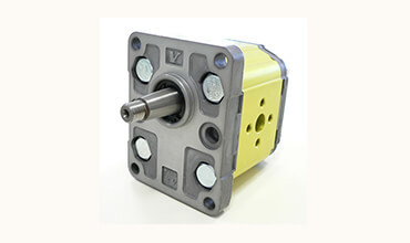
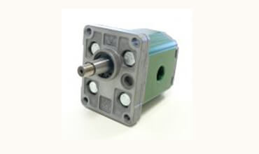
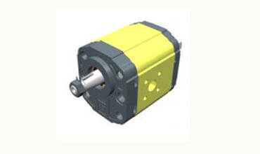
The rotation verse is clockwise or counterclockwise, and you can reverse it without adding any components, so you can optimize storage space and adapt the pump to your needs. In this catalogue from pages 18 to 29, you will find instructions for changing the rotation verse of our unidirectional pumps, divided by type.
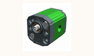
The rotation verse is clockwise or counterclockwise, and you can reverse it without adding any components, so you can optimize storage space and adapt the motor to your needs. In this catalogue from pages 18 to 29, you will find instructions for changing the rotation verse of our unidirectional motors, divided by type.
In my continuing series on a mechanic’s guide to a hydraulic system, we have already discussed the importance of the fluid’s viscosity, cleanliness, flow rate, cooling and reservoir level to ensure a positive head pressure (NPSHA) to the suction side of the pump. Now, it’s time to discuss the heart of the hydraulic system—the pump.
Proper selection and operation of the pump will have a major influence on the system’s overall performance, operational efficiency and operational cost.
In all pump classes, you will hear “Pumps don’t suck nor do they pump pressure.” Although pumps come in a variety of shapes and sizes with different operating mechanisms, they all do one thing—create flow by transferring mechanical energy to fluid velocity.
Because the pump has a maximum speed rating, most industrial hydraulic systems use either a motor with a nominal rating of 1,200 rpm (actual 1,140 rpm) or nominal rating of 1,800 rpm (actual 1,750 rpm). On mobile hydraulic systems that use internal combustion engines, a variable drive is used to regulate the output speed. It is important that the operators do not drop below the minimum or exceed the maximum speed limit of the pump.
Where a dynamic (centrifugal) pump’s capacity (gpm) will go down as head pressure increases, a positive displacement pump delivers a constant output flow (gpm) regardless of the head pressure.
Another method of representing the size of a positive displacement pump is the nominal flow at a specific drive speed. Hydraulic pump manufacturers simply refer to these pumps sizes as 8 gpm, 10 gpm, and so on.
In theory, a pump that displaces 25 in.3/rev will deliver 25 in.3 of fluid for each revolution. In actuality, the pump output will be reduced due to internal slippage (the fluid flows from the pump’s output to the pump’s input). For a given clearance, the higher the outlet pressure, the higher the slippage.
Multiple applications exist where fixed-displacement pumps do the job. Fixed-displacement pumps can be selected for use as long as the following conditions don’t need to be met:
It is imperative to select a pump of precise size. A fixed-displacement pump is a positive displacement type where the amount of displacement (gpm) cannot be varied, only by changing the drive speed to the pump. Since industrial hydraulic systems are usually driven by constant speed electric motors, applications of a fixed-displacement pump are limited. In the next article, I will discuss the different types of fixed-displacement pumps and their applications.

Wilson Company carries a deep inventory of pneumatic and hydraulic parts and supplies. We’re your one-stop source for motion control products, systems solutions. Whatever components or designs you need for your business or project, Wilson Company has all the answers you’re looking for.
Family owned and operated since 1965, Wilson Company has expanded to six locations in Dallas, Fort Worth, Houston, Texarkana, Austin, and San Antonio. In addition to designing and installing fluid power systems and components, we’ve also offered education programs about hydraulic and pneumatic principles and system design.
Pneumatic systems are ideal for situations that don’t require the same force that hydraulic pumps and systems typically generate. Since they don’t have a lot of complex moving parts or rely on electricity, pneumatic tools are safer and easier to maintain than electric sources of energy, and usually much less expensive.
When a project needs an energy source with more force or one that allows for better accuracy, many companies turn to hydraulic power. Hydraulics use pressurized liquids and fluids to generate and transfer energy, moving liquids through tubes, actuators, filters, and pressurizers to help move and activate automated components and mechanisms.
Hydraulic systems are frequently used in heavy construction applications. Hydraulic pumps are powered by large equipment like bulldozers, cranes, and diggers to pressurize incoming fluids, which in turn put arms, blades, and lifting devices in motion. Industrial companies also use hydraulic power to operate robotic arms, lathes, and presses.
Wilson Company’s services go beyond supplying and installing equipment. We offer hands-on training courses in hydraulic technology and pneumatic operations, in which classmates build, adjust, inspect and analyze energy circuits from schematic designs. Students with technical backgrounds or basic aptitude learn all about the maintenance and operation of heavy industrial equipment through textbooks and laboratory work.
Hydraulic and pneumatic power systems are suitable for a broad range of companies, industries, and businesses. With Wilson Company"s vast experience and technical know-how, we give our customers power solutions that are efficient and cost-effective, along with extensive product support and customer service.
Mining: Hydraulic mining systems including lifters, excavators, and rock movers, as well as pneumatic power for drills, wrenches, loaders, and mining equipment
Government defense & security: Hydraulic lifting of jets for construction, integrated systems for intrusion detection, power for unmanned vehicles, fluid purification, and more
Transportation: Moving natural resources, hydraulic systems for aircraft, spike drivers and ballast regulators for railroad companies, pneumatic couplers for rail cars and vehicles, and more
Knowledge. Our engineering specialists know all about traditional hydraulic and pneumatic equipment and are always on top of the latest trends and technologies that can help your business.
Convenience. With offices in Houston, Dallas, Fort Worth, Austin, San Antonio, and Texarkana, Wilson Company easily handles the hydraulic and pneumatic power needs for all of Eastern Texas.
To find out more about what Wilson Company does and how we can help you take advantage of hydraulic or pneumatic power solutions, contact us using our online form, or call us toll-free at 1-800-580-1212. Our certified experts will guide you through all your options, help you decide what solution is right for you, and get started ordering the supplies and installation for hydraulic or pneumatic power.

Hydraulic motors are generally one of the largest components of a hydraulic system, which makes ensuring you have the correct part vital to the efficient running of your hydraulic system. These motors convert hydraulic pressure and flow into torque and angular displacement. Hydraulic motors are mechanical rotary actuators that are designed to run hydraulic systems at different speeds and operate at different flow levels. They work in tandem with a hydraulic pump providing the force and supply the motion to move an external load.
The 3 types of hydraulic motor in common use today are gear, vane and piston motors; less commonly used motors include gerotor orbital motors. Additionally, piston motors can be categorised into axial piston motors and radial piston motors. Hydraulic motors can operate either bi-directionally or unidirectional and can be fixed-displacement or variable-displacement. Variable-displacement motors vary the flow rate by changing displacement. Whereas fixed-displacement motors provide a constant input flow driving a load at a constant speed and torque.
Knowing the maximum operating pressure, speed and torque the motor will need and knowing its displacement and flow requirements within a hydraulic system is just as vital. Does the motor need a bio-based, environmentally friendly or fire-resistant fluid? Can contamination be an issue? Understanding the hydraulic motor’s system’s requirements will help you to know the answer to these questions. Knowing the size and weight of the motor is important as this will affect the final size and weight of the hydraulic system.
We are leading suppliers of dependable and low-cost hydraulic motors. Due to our long-lasting relationships with the major hydraulics manufacturers, we are able to offer tier 1 pricing for many hydraulic components. So not only will you be safe in the knowledge your hydraulic system is made to the rigorous standards you would expect, but it will also be cost-effective.
Please don’t hesitate to contact us if you have any questions about our range of hydraulic motors or hydraulic systems in general. Our friendly and informative team is always on hand to help you find the right component for your job.


 8613371530291