
variable displacement hydraulic pump symbol price
Designed for power and speed, the Oilgear PVV open-loop axial-piston hydraulic pumps can handle large, heavy-duty systems. Manufactured with advanced engineering and computer-optimized, the PVV pump range delivers up to 450 Bar / 560 horespower which equates to four times the horsepower at less than half the cost of other manufacturers pumps.
With it"s compact design available in several displacements (200-540cc/rev), the PVV pumps offer a large selection of readily interchangeable controls. With improved response controls and reduced noise levels, its rugged cylinder design enhances performance.
The patented, pressure lubricated swashblock design offers high performance for high-cycling operations. It also contributes to the pump’s ability to run on low-viscosity fluids, including high water content, fire-resistant and other special fluids.
Zeus Hydratech fully supports the PVV pump product line and is the only valid source for OEM parts. All Oilgear repairs are machined and tested per our original factory specifications.

Designed for power and speed, the Oilgear PVV open-loop axial-piston hydraulic pumps can handle large, heavy-duty systems. Manufactured with advanced engineering and computer-optimized, the PVV pump range delivers up to 450 Bar / 560 horespower which equates to four times the horsepower at less than half the cost of other manufacturers pumps.
With it"s compact design available in several displacements, the PVV pumps offer a large selection of readily interchangeable controls. With improved response controls and reduced noise levels, its rugged cylinder design enhances performance.
The patented, pressure lubricated swashblock design offers high performance for high-cycling operations. It also contributes to the pump’s ability to run on low-viscosity fluids, including high water content, fire-resistant and other special fluids.
Zeus Hydratech fully supports the Oilgear PVV pump product line and is the only valid source for OEM parts. All Oilgear repairs are machined and tested per our original factory specifications.

With fast control response and superior performance, the PVG is a variable-displacement axial-piston pump designed to take on your most demanding applications. It offers high-pressure, superior performance in a compact design — while thriving on low-viscosity fluids.
With fast control response and superior performance, the PVG is a variable-displacement axial-piston pump designed to take on your most demanding applications. It offers high-pressure, superior performance in a compact design — while thriving on low-viscosity fluids.
With fast control response and superior performance, the PVG is a variable-displacement axial-piston pump designed to take on your most demanding applications. It offers high-pressure, superior performance in a compact design — while thriving on low-viscosity fluids.
With fast control response and superior performance, the PVG is a variable-displacement axial-piston pump designed to take on your most demanding applications. It offers high-pressure, superior performance in a compact design — while thriving on low-viscosity fluids.
With fast control response and superior performance, the PVG is a variable-displacement axial-piston pump designed to take on your most demanding applications. It offers high-pressure, superior performance in a compact design — while thriving on low-viscosity fluids.
With fast control response and superior performance, the PVG is a variable-displacement axial-piston pump designed to take on your most demanding applications. It offers high-pressure, superior performance in a compact design — while thriving on low-viscosity fluids.
With fast control response and superior performance, the PVG is a variable-displacement axial-piston pump designed to take on your most demanding applications. It offers high-pressure, superior performance in a compact design — while thriving on low-viscosity fluids.
When you need peak performance from a variable-displacement axial-piston pump, the Oilgear pump PVV line is ready. No matter what pressure and flow demands you face, these pumps rise to the challenge.
When you need peak performance from a variable-displacement axial-piston pump, the Oilgear pump PVV line is ready. No matter what pressure and flow demands you face, these pumps rise to the challenge.
When you need peak performance from a variable-displacement axial-piston pump, the Oilgear pump PVV line is ready. No matter what pressure and flow demands you face, these pumps rise to the challenge.
When you need peak performance from a variable-displacement axial-piston pump, the Oilgear pump PVV line is ready. No matter what pressure and flow demands you face, these pumps rise to the challenge.
Quiet operation, high efficiency and compact design — all available at a competitive price. That’s what Oilgear PVWC closed-loop, hydrostatic axial-piston hydraulic pumps bring to the table. All designed around our proven rotating group.
Quiet operation, high efficiency and compact design — all available at a competitive price. That’s what Oilgear PVWC closed-loop, hydrostatic axial-piston hydraulic pumps bring to the table. All designed around our proven rotating group.
Quiet operation, high efficiency and compact design — all available at a competitive price. That’s what Oilgear PVWC closed-loop, hydrostatic axial-piston hydraulic pumps bring to the table. All designed around our proven rotating group.
Designed to be cost-effective, stable and low-maintenance, PVWJ is a variable-displacement axial-piston pump with a medium control response. Like all Oilgear pumps, it thrives on low-viscosity fluids — and comes in a variety of frame sizes and available displacement rates.
Designed to be cost-effective, stable and low-maintenance, PVWJ is a variable-displacement axial-piston pump with a medium control response. Like all Oilgear pumps, it thrives on low-viscosity fluids — and comes in a variety of frame sizes and available displacement rates.
Designed to be cost-effective, stable and low-maintenance, PVWJ is a variable-displacement axial-piston pump with a medium control response. Like all Oilgear pumps, it thrives on low-viscosity fluids — and comes in a variety of frame sizes and available displacement rates.
Designed to be cost-effective, stable and low-maintenance, PVWJ is a variable-displacement axial-piston pump with a medium control response. Like all Oilgear pumps, it thrives on low-viscosity fluids — and comes in a variety of frame sizes and available displacement rates.
Designed to be cost-effective, stable and low-maintenance, PVWJ is a variable-displacement axial-piston pump with a medium control response. Like all Oilgear pumps, it thrives on low-viscosity fluids — and comes in a variety of frame sizes and available displacement rates.
Designed to be cost-effective, stable and low-maintenance, PVWJ is a variable-displacement axial-piston pump with a medium control response. Like all Oilgear pumps, it thrives on low-viscosity fluids — and comes in a variety of frame sizes and available displacement rates.
Designed to be cost-effective, stable and low-maintenance, PVWJ is a variable-displacement axial-piston pump with a medium control response. Like all Oilgear pumps, it thrives on low-viscosity fluids—and comes in a variety of frame sizes and available displacement rates.
Designed to be cost-effective, stable and low-maintenance, PVWJ is a variable-displacement axial-piston pump with a medium control response. Like all Oilgear pumps, it thrives on low-viscosity fluids — and comes in a variety of frame sizes and available displacement rates.
Designed to be cost-effective, stable and low-maintenance, PVWJ is a variable-displacement axial-piston pump with a medium control response. Like all Oilgear pumps, it thrives on low-viscosity fluids — and comes in a variety of frame sizes and available displacement rates.
Designed to be cost-effective, stable and low-maintenance, PVWJ is a variable-displacement axial-piston pump with a medium control response. Like all Oilgear pumps, it thrives on low-viscosity fluids — and comes in a variety of frame sizes and available displacement rates.
Extremely effective across numerous industrial applications that require quick response in extreme environments, the XD5 series of pumps offer lightning-fast control response on both low-viscosity fluids and standard hydraulic oil. Engineered to handle the most challenging environments, they have been designed to be a high-performance solution for demanding mobile applications.

When you need peak performance from a variable-displacement axial-piston pump, the Oilgear pump PVV line is ready. No matter what pressure and flow demands you face, these pumps rise to the challenge.
Designed for power and speed, PVV open-loop axial-piston hydraulic pumps by Oilgear can handle large, heavy-duty systems. Made with advanced engineering and computer-optimized, the PVV line delivers up to 560 horsepower. That’s four times the horsepower at less than half the cost of other models.
A compact design available in several displacements, PVV pumps offer a large selection of readily interchangeable controls. With improved response controls and reduced noise levels, its rugged cylinder design enhances performance.
The patented pressure lubricated swashblock design offers high performance for high-cycling operations. It also contributes to the pump’s ability to run on low-viscosity — including high water content, fire-resistant and other special fluids. That fluid compatibility continues to set Oilgear apart.
Oilgear fully supports the PVV pump product line and is the only valid source for OEM parts. All Oilgear repairs are machined and tested per our original factory specifications.
Oilgear makes some of the longest-lasting, most reliable pumps in the world. Learn more about the proprietary design of the Oilgear variable-displacement, axial-piston pump line.

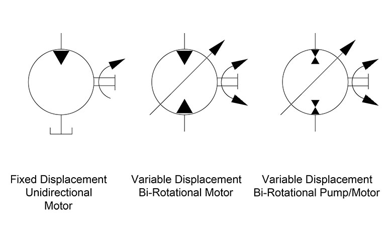
The base symbol for the hydraulic pump (Figure 1) is actually quite simple. It starts with the standard circle and a directional arrow pointing out one end from within that circle. The solid-filled triangle makes this a hydraulic pump while pneumatic pumps (and most pneumatic symbols) are outlines only. There exist no other options for this particular pump symbol, which can be accurately described as a fixed displacement, unidirectional hydraulic pump.
It’s rare to see a pump in any orientation but North when reading schematics, and they are often paired below to a line terminating into the reservoir symbol, which I show just once. If multiple components such as filters, ball valves, accessories or even other pumps are used, the tank line can be widened as needed. Other designers prefer to show every tank line terminate into the same small symbol, while others will place a tank symbol right at every component requiring it, just is done in electrics with the ground symbol.
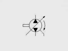
My favorite symbol to express the pressure compensated pump is the smaller of the two symbols in Figure 2. This is a slightly more detailed example of the symbol I depicted in Hydraulic Symbology 101, and I’ve added color to help with the explanation. Don’t worry about the scary looking object to the right, we’ll get to that shortly.
For this particular symbol of the pressure compensated pump, the shaft sticks out to the right, which can be attached to the square of a combustion engine prime mover symbol or the circular symbol of an electric motor. The semicircular arrow shows us the shaft rotates clockwise, or to the right since rotation direction is always observed from the vantage point of the shaft end.
The variable arrow bisects the pump symbol and of course tells us the pump is adjustable displacement. The method of displacement control is defined by the compound symbol attached to the pump’s left. Under the long rectangle is a spring with a variability arrow, which represents the pressure compensator spring, itself semienclosed and attached to the bottom of the pump’s variable arrow. Opposite the spring is a triangular input for pilot pressure, and this juxtaposition is intentional.
The orange pilot signal is taken directly from the red system pressure line exiting the pump, with the dashed orange line confirming it is indeed pilot energy. The spring setting fights with pilot pressure to infinitely and smoothly adjust the flow rate to match downstream pressure drop equal to the compensator setting. For example, if the setting is 3,000 psi, any downstream combination of load and flow-related pressure below 3,000 psi will see the spring maintain full displacement of the swashplate, producing full pump flow.
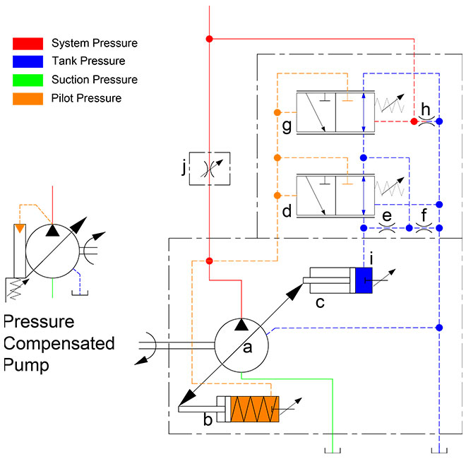
Moving along to the scary looking thing on the right, we have here the detailed breakdown of the variable displacement, pressure compensated, load-sensing, unidirectional hydraulic pump. You’ve likely seen this symbol before because the manufacturers prefer to show this level of detail, especially to differentiate advanced controls options like remoted compensation or horsepower control. This “load-sensing pump” will make sense to you shortly. I’ll warn that it will take some time and effort to understand this symbol as you methodically work through the rest of this article.
Starting with the pump (a), it has the diagonal variability arrow bisecting the circle and is attached to the rod ends of two cylinders. Cylinder (b) is the bias piston meant to force the pump to full displacement whenever possible, a task made easier by a spring pushing the piston forward. Some pumps make do with only a strong spring, but this example is balanced with pilot energy. Affixed on the right is a tiny object with a variable arrow, which can be adjusted to move left or right within the cylinder. Not all pumps have this additional component, which is the minimum volume stop, preventing the bias piston from retracting fully, which subsequently prevents fully standby of the pump.
If you’re familiar with cylinder symbols, you’ll see that (c) also looks like a single acting cylinder with a stroke adjustor at the cap side. This is the control piston, which will always be a larger bore diameter than the bias piston. The control piston’s stroke adjustment is called the maximum volume stop and is used to modify the maximum displacement of the pump, convenient when you need a displacement between the two sizes available for the chosen pump. The two “cylinders” are attached by their rods to each other, and as one extends the other must retract and vice versa, and I’ll explain shortly why and how their battle develops.
Because all load sensing pumps must be pressure compensated, I’ll start with (d), which is the pressure compensator. Although it looks different, it is essentially a relief valve governing the control piston (c). It’s shown in its neutral condition, where it bleeds the chamber of the control piston (c) through orifice (e), orifice (f), and also through the other compensator (g) where it can choose any flow path directly to tank. Regardless of its flow path, pilot energy inside the control piston (c) is zero, so it loses the battle with the bias piston (b) and the pump is on full displacement pump at its highest rate.
The load sense compensator (g) looks much the same as the pressure compensator (d) and is similar in function except where it takes pilot energy and what it does with it afterward. As with the pressure compensator symbol (d), it is a 3-way, 2-position valve that is spring-offset with adjustable pressure settings for both. Each is supplemented with the parallel lines above and below both positional envelopes, and these lines tell us the valve is infinitely variable between the two positions.
The variable orifice at (j) could be any flow control, lever valve or proportional valve used to adjust flow (which creates backpressure when reduced) in the red system pressure line starting at the pump. You can see the node just after the pump outlet that combines system pressure with pilot lines supplying the bias piston and both compensators. Let’s first take the load sense compensator (g) out of the picture and describe the pressure compensator (d) and what occurs during operation.
When the pump fires up, and assuming all downstream directional valves are closed, the spring inside the bias piston (b) fully strokes the pump to max displacement. This immediately creates pressure in the work and pilot lines as fluid fills the plumbing with no exit strategy, and this rise in pressure at the pilot line at (d) forces the pressure compensator to shift to the right. The second pilot line attached to the top of compensator (d) allows pilot energy to enter through line (i) where it fills the control piston (c) rapidly. Because the control piston is larger bore than the bias piston, it wins the fight and moves the pump’s variable arrow to reduce displacement until the only flow is what is required to overcome leakage. The pump is on “standby.”
Now when a downstream directional valve is opened, a flow path is created that drops system pressure to below the setting of the (d) compensator, and it immediately succumbs to spring pressure and snaps back to near its neutral setting, opening the drain lines once again to tank. The orifices (e) and (f) dampen the motion of the compensator, preventing rapid oscillations, but the orifice also prevents pressure spikes into the pump’s case. They also ensure that pressure doesn’t decay from the control piston (c) when system pressure degrades rapidly for fractions of a second. Flow from the pump will be balanced by the opposing bias and control pistons to match downstream pressure drop at exactly the pressure compensator setting.
Finally, we look at the operation of the load sense compensator (g) shown on top. It also receives a pilot signal directly from the pump outlet, but you’ll see that it also gets a competing signal from the work line after the metering orifice. The pressure signal at (g) compares the combined effort of the spring value and the load-sense pilot signal just before (h). The setting of the pressure compensator (d) is much higher than the setting of the load sense compensator (g), which is set to create reasonable pressure drop across (j). If the (d) compensator is set to 3,000 psi, it’ll only see this pressure on standby or max load pressure, while the (g) compensator might be set to 300 psi, where it measures pressure drop across (j) valve.
Typically a load sense circuit will have multiple orifices in a load sense network all feeding back a pilot signal to the load sense compensator (g), where it picks the highest pressure signal and meters the pump’s flow to match that pressure differential and provides just enough flow to satisfy the desired flow rate at the desired work pressure plus the pressure of the load sense compensator’s spring value. For example, if load pressure is 1,000 psi, the pump will hold pressure at 1,300 psi, providing the extra 300 psi just to create flow across the metering valve (j).
This symbol shows you that no matter the initial feeling of complexity, breaking down any schematic thoughtfully reveals its purpose of design. I fell in love with hydraulics when I learned about the load sensing concept. That just using columns of fluid pressure to create an efficient supply and demand scenario to satisfy many downstream actuators with essentially the exact flow and pressure they need for the job, and little more, I found exhilarating.

Established in year2020, Shree Ganesh Hydraulicshas made a well-recognized name asAuthorized Wholesale Dealer and retailerof THM HUADE Axial Piston Pump, Vane Pump, Orbital Motor High Pressure Gear Pump etc.We have achieved expertise in catering to the requirements of our clients exactly as per their needs. We emphasize on stringent quality standards in order to ensure that the products provided to our clients is always optimum to its level.

The top symbol shows a fixed displacement hydraulic pump that rotates in an anticlockwise direction (shown by the arrow) when viewed onto the drive flange and drive-shaft. The black triangle shows it is a hydraulic pump and which direction the flow will go in.
The middle symbol has an arrow through it indicating a variable displacement pump. It also shows a case drain line coming from the side of the pump casing. Generally, it is only fixed displacement pumps that can work without a case drain line.

For novices in the fluid power industry, lack of understanding between the fixed flow and variable flow pumping concepts is quite common. A hydraulic pump has one mission, and that is to transform incoming mechanical energy at its shaft into hydraulic energy capable of transferring force to actuators somewhere downstream. This transfer of force is common to both fixed and variable pumps, but the method delivery is quite different.
The displacement of a pump is defined by the theoretical volume the gears, vanes or pistons will displace in one revolution. If a pump is 30 cc, it will theoretically push 30 ml of fluid in a single rotation, or about 1.8 in.3. With a fixed displacement pump, these 30 cm3 do not change, regardless of how the pump is controlled or what occurs downstream. In reality, actual flow varies based on efficiency, speed and pressure, but that’s a different story. If you need less flow than the pump is rated for, the excess flow must be diverted or relieved to tank.
A variable displacement pump has a method of increasing or reducing displacement either manually, hydraulically or electronically. The method of displacement change depends upon the pump’s structure, differing between piston and vane pumps, and between those two, iterations still.
An axial piston pump’s maximum displacement is determined by the quantity and bore area of the pistons multiplied by the stroke length. Although the stroke length can be fixed, such as with most radial and bent-axis piston motors, the stroke can also be varied. Variable displacement axial piston pumps use a swashplate to guide the pistons as they reciprocate while rotating about the shaft’s axis. The angle the swashplate sits at relative to the pistons dictates how long or short the piston stroke is, and with variable pumps, the swashplate is supported by bearings or bushings.
On opposing sides of the swashplate sits a bias piston (and spring) and a control piston. A variable displacement piston pump is designed to be “on stroke,” meaning it wants to pump with full displacement whenever possible. The control piston is operated by what is essentially a relief valve, and if downstream pressure rises above this pressure compensator setting, it will push the control piston out to reduce the angle of the swashplate. With the swashplate angle reduced, the pistons now travel a fraction of their stroke potential. Because displacement is dictated by the area, quantity and stroke of the pistons, pump volume is now reduced. If downstream pressure is still higher than the compensator setting, the stroke will be reduced until the swashplate angle is nearly zero, where it only pumps enough to maintain lubrication.
Swashplate angle can be changed mechanically, with a lever or wheel, but in advanced applications, electro-proportional valves operate the control piston to adjust pump flow as required. This is an advanced concept used in closed loop electronic control applications. A proportional pressure valve will adjust the control piston of the pump with guidance from the PLC, providing exact flow required by the machine under varying conditions.

The top symbol shows a fixed displacement hydraulic pump that rotates in an anticlockwise direction (shown by the arrow) when viewed onto the drive flange and drive-shaft. The black triangle shows it is a hydraulic pump and which direction the flow will go in.
The middle symbol has an arrow through it indicating a variable displacement pump. It also shows a case drain line coming from the side of the pump casing. Generally, it is only fixed displacement pumps that can work without a case drain line.

Hydraulic pumps are mechanisms in hydraulic systems that move hydraulic fluid from point to point initiating the production of hydraulic power. Hydraulic pumps are sometimes incorrectly referred to as “hydrolic” pumps.
They are an important device overall in the hydraulics field, a special kind of power transmission which controls the energy which moving fluids transmit while under pressure and change into mechanical energy. Other kinds of pumps utilized to transmit hydraulic fluids could also be referred to as hydraulic pumps. There is a wide range of contexts in which hydraulic systems are applied, hence they are very important in many commercial, industrial, and consumer utilities.
“Power transmission” alludes to the complete procedure of technologically changing energy into a beneficial form for practical applications. Mechanical power, electrical power, and fluid power are the three major branches that make up the power transmission field. Fluid power covers the usage of moving gas and moving fluids for the transmission of power. Hydraulics are then considered as a sub category of fluid power that focuses on fluid use in opposition to gas use. The other fluid power field is known as pneumatics and it’s focused on the storage and release of energy with compressed gas.
"Pascal"s Law" applies to confined liquids. Thus, in order for liquids to act hydraulically, they must be contained within a system. A hydraulic power pack or hydraulic power unit is a confined mechanical system that utilizes liquid hydraulically. Despite the fact that specific operating systems vary, all hydraulic power units share the same basic components. A reservoir, valves, a piping/tubing system, a pump, and actuators are examples of these components. Similarly, despite their versatility and adaptability, these mechanisms work together in related operating processes at the heart of all hydraulic power packs.
The hydraulic reservoir"s function is to hold a volume of liquid, transfer heat from the system, permit solid pollutants to settle, and aid in releasing moisture and air from the liquid.
Mechanical energy is changed to hydraulic energy by the hydraulic pump. This is accomplished through the movement of liquid, which serves as the transmission medium. All hydraulic pumps operate on the same basic principle of dispensing fluid volume against a resistive load or pressure.
Hydraulic valves are utilized to start, stop, and direct liquid flow in a system. Hydraulic valves are made of spools or poppets and can be actuated hydraulically, pneumatically, manually, electrically, or mechanically.
The end result of Pascal"s law is hydraulic actuators. This is the point at which hydraulic energy is transformed back to mechanical energy. This can be accomplished by using a hydraulic cylinder to transform hydraulic energy into linear movement and work or a hydraulic motor to transform hydraulic energy into rotational motion and work. Hydraulic motors and hydraulic cylinders, like hydraulic pumps, have various subtypes, each meant for specific design use.
The essence of hydraulics can be found in a fundamental physical fact: fluids are incompressible. (As a result, fluids more closely resemble solids than compressible gasses) The incompressible essence of fluid allows it to transfer force and speed very efficiently. This fact is summed up by a variant of "Pascal"s Principle," which states that virtually all pressure enforced on any part of a fluid is transferred to every other part of the fluid. This scientific principle states, in other words, that pressure applied to a fluid transmits equally in all directions.
Furthermore, the force transferred through a fluid has the ability to multiply as it moves. In a slightly more abstract sense, because fluids are incompressible, pressurized fluids should keep a consistent pressure just as they move. Pressure is defined mathematically as a force acting per particular area unit (P = F/A). A simplified version of this equation shows that force is the product of area and pressure (F = P x A). Thus, by varying the size or area of various parts inside a hydraulic system, the force acting inside the pump can be adjusted accordingly (to either greater or lesser). The need for pressure to remain constant is what causes force and area to mirror each other (on the basis of either shrinking or growing). A hydraulic system with a piston five times larger than a second piston can demonstrate this force-area relationship. When a force (e.g., 50lbs) is exerted on the smaller piston, it is multiplied by five (e.g., 250 lbs) and transmitted to the larger piston via the hydraulic system.
Hydraulics is built on fluids’ chemical properties and the physical relationship between pressure, area, and force. Overall, hydraulic applications allow human operators to generate and exert immense mechanical force with little to no physical effort. Within hydraulic systems, both oil and water are used to transmit power. The use of oil, on the other hand, is far more common, owing in part to its extremely incompressible nature.
Pressure relief valves prevent excess pressure by regulating the actuators’ output and redirecting liquid back to the reservoir when necessary. Directional control valves are used to change the size and direction of hydraulic fluid flow.
While hydraulic power transmission is remarkably useful in a wide range of professional applications, relying solely on one type of power transmission is generally unwise. On the contrary, the most efficient strategy is to combine a wide range of power transmissions (pneumatic, hydraulic, mechanical, and electrical). As a result, hydraulic systems must be carefully embedded into an overall power transmission strategy for the specific commercial application. It is necessary to invest in locating trustworthy and skilled hydraulic manufacturers/suppliers who can aid in the development and implementation of an overall hydraulic strategy.
The intended use of a hydraulic pump must be considered when selecting a specific type. This is significant because some pumps may only perform one function, whereas others allow for greater flexibility.
The pump"s material composition must also be considered in the application context. The cylinders, pistons, and gears are frequently made of long-lasting materials like aluminum, stainless steel, or steel that can withstand the continuous wear of repeated pumping. The materials must be able to withstand not only the process but also the hydraulic fluids. Composite fluids frequently contain oils, polyalkylene glycols, esters, butanol, and corrosion inhibitors (though water is used in some instances). The operating temperature, flash point, and viscosity of these fluids differ.
In addition to material, manufacturers must compare hydraulic pump operating specifications to make sure that intended utilization does not exceed pump abilities. The many variables in hydraulic pump functionality include maximum operating pressure, continuous operating pressure, horsepower, operating speed, power source, pump weight, and maximum fluid flow. Standard measurements like length, rod extension, and diameter should be compared as well. Because hydraulic pumps are used in lifts, cranes, motors, and other heavy machinery, they must meet strict operating specifications.
It is critical to recall that the overall power generated by any hydraulic drive system is influenced by various inefficiencies that must be considered in order to get the most out of the system. The presence of air bubbles within a hydraulic drive, for example, is known for changing the direction of the energy flow inside the system (since energy is wasted on the way to the actuators on bubble compression). Using a hydraulic drive system requires identifying shortfalls and selecting the best parts to mitigate their effects. A hydraulic pump is the "generator" side of a hydraulic system that initiates the hydraulic procedure (as opposed to the "actuator" side that completes the hydraulic procedure). Regardless of disparities, all hydraulic pumps are responsible for displacing liquid volume and transporting it to the actuator(s) from the reservoir via the tubing system. Some form of internal combustion system typically powers pumps.
While the operation of hydraulic pumps is normally the same, these mechanisms can be split into basic categories. There are two types of hydraulic pumps to consider: gear pumps and piston pumps. Radial and axial piston pumps are types of piston pumps. Axial pumps produce linear motion, whereas radial pumps can produce rotary motion. The gear pump category is further subdivided into external gear pumps and internal gear pumps.
Each type of hydraulic pump, regardless of piston or gear, is either double-action or single-action. Single-action pumps can only pull, push, or lift in one direction, while double-action pumps can pull, push, or lift in multiple directions.
Vane pumps are positive displacement pumps that maintain a constant flow rate under varying pressures. It is a pump that self-primes. It is referred to as a "vane pump" because the effect of the vane pressurizes the liquid.
This pump has a variable number of vanes mounted onto a rotor that rotates within the cavity. These vanes may be variable in length and tensioned to maintain contact with the wall while the pump draws power. The pump also features a pressure relief valve, which prevents pressure rise inside the pump from damaging it.
Internal gear pumps and external gear pumps are the two main types of hydraulic gear pumps. Pumps with external gears have two spur gears, the spurs of which are all externally arranged. Internal gear pumps also feature two spur gears, and the spurs of both gears are internally arranged, with one gear spinning around inside the other.
Both types of gear pumps deliver a consistent amount of liquid with each spinning of the gears. Hydraulic gear pumps are popular due to their versatility, effectiveness, and fairly simple design. Furthermore, because they are obtainable in a variety of configurations, they can be used in a wide range of consumer, industrial, and commercial product contexts.
Hydraulic ram pumps are cyclic machines that use water power, also referred to as hydropower, to transport water to a higher level than its original source. This hydraulic pump type is powered solely by the momentum of moving or falling water.
Ram pumps are a common type of hydraulic pump, especially among other types of hydraulic water pumps. Hydraulic ram pumps are utilized to move the water in the waste management, agricultural, sewage, plumbing, manufacturing, and engineering industries, though only about ten percent of the water utilized to run the pump gets to the planned end point.
Despite this disadvantage, using hydropower instead of an external energy source to power this kind of pump makes it a prominent choice in developing countries where the availability of the fuel and electricity required to energize motorized pumps is limited. The use of hydropower also reduces energy consumption for industrial factories and plants significantly. Having only two moving parts is another advantage of the hydraulic ram, making installation fairly simple in areas with free falling or flowing water. The water amount and the rate at which it falls have an important effect on the pump"s success. It is critical to keep this in mind when choosing a location for a pump and a water source. Length, size, diameter, minimum and maximum flow rates, and speed of operation are all important factors to consider.
Hydraulic water pumps are machines that move water from one location to another. Because water pumps are used in so many different applications, there are numerous hydraulic water pump variations.
Water pumps are useful in a variety of situations. Hydraulic pumps can be used to direct water where it is needed in industry, where water is often an ingredient in an industrial process or product. Water pumps are essential in supplying water to people in homes, particularly in rural residences that are not linked to a large sewage circuit. Water pumps are required in commercial settings to transport water to the upper floors of high rise buildings. Hydraulic water pumps in all of these situations could be powered by fuel, electricity, or even by hand, as is the situation with hydraulic hand pumps.
Water pumps in developed economies are typically automated and powered by electricity. Alternative pumping tools are frequently used in developing economies where dependable and cost effective sources of electricity and fuel are scarce. Hydraulic ram pumps, for example, can deliver water to remote locations without the use of electricity or fuel. These pumps rely solely on a moving stream of water’s force and a properly configured number of valves, tubes, and compression chambers.
Electric hydraulic pumps are hydraulic liquid transmission machines that use electricity to operate. They are frequently used to transfer hydraulic liquid from a reservoir to an actuator, like a hydraulic cylinder. These actuation mechanisms are an essential component of a wide range of hydraulic machinery.
There are several different types of hydraulic pumps, but the defining feature of each type is the use of pressurized fluids to accomplish a job. The natural characteristics of water, for example, are harnessed in the particular instance of hydraulic water pumps to transport water from one location to another. Hydraulic gear pumps and hydraulic piston pumps work in the same way to help actuate the motion of a piston in a mechanical system.
Despite the fact that there are numerous varieties of each of these pump mechanisms, all of them are powered by electricity. In such instances, an electric current flows through the motor, which turns impellers or other devices inside the pump system to create pressure differences; these differential pressure levels enable fluids to flow through the pump. Pump systems of this type can be utilized to direct hydraulic liquid to industrial machines such as commercial equipment like elevators or excavators.
Hydraulic hand pumps are fluid transmission machines that utilize the mechanical force generated by a manually operated actuator. A manually operated actuator could be a lever, a toggle, a handle, or any of a variety of other parts. Hydraulic hand pumps are utilized for hydraulic fluid distribution, water pumping, and various other applications.
Hydraulic hand pumps may be utilized for a variety of tasks, including hydraulic liquid direction to circuits in helicopters and other aircraft, instrument calibration, and piston actuation in hydraulic cylinders. Hydraulic hand pumps of this type use manual power to put hydraulic fluids under pressure. They can be utilized to test the pressure in a variety of devices such as hoses, pipes, valves, sprinklers, and heat exchangers systems. Hand pumps are extraordinarily simple to use.
Each hydraulic hand pump has a lever or other actuation handle linked to the pump that, when pulled and pushed, causes the hydraulic liquid in the pump"s system to be depressurized or pressurized. This action, in the instance of a hydraulic machine, provides power to the devices to which the pump is attached. The actuation of a water pump causes the liquid to be pulled from its source and transferred to another location. Hydraulic hand pumps will remain relevant as long as hydraulics are used in the commerce industry, owing to their simplicity and easy usage.
12V hydraulic pumps are hydraulic power devices that operate on 12 volts DC supplied by a battery or motor. These are specially designed processes that, like all hydraulic pumps, are applied in commercial, industrial, and consumer places to convert kinetic energy into beneficial mechanical energy through pressurized viscous liquids. This converted energy is put to use in a variety of industries.
Hydraulic pumps are commonly used to pull, push, and lift heavy loads in motorized and vehicle machines. Hydraulic water pumps may also be powered by 12V batteries and are used to move water out of or into the desired location. These electric hydraulic pumps are common since they run on small batteries, allowing for ease of portability. Such portability is sometimes required in waste removal systems and vehiclies. In addition to portable and compact models, options include variable amp hour productions, rechargeable battery pumps, and variable weights.
While non rechargeable alkaline 12V hydraulic pumps are used, rechargeable ones are much more common because they enable a continuous flow. More considerations include minimum discharge flow, maximum discharge pressure, discharge size, and inlet size. As 12V batteries are able to pump up to 150 feet from the ground, it is imperative to choose the right pump for a given use.
Air hydraulic pumps are hydraulic power devices that use compressed air to stimulate a pump mechanism, generating useful energy from a pressurized liquid. These devices are also known as pneumatic hydraulic pumps and are applied in a variety of industries to assist in the lifting of heavy loads and transportation of materials with minimal initial force.
Air pumps, like all hydraulic pumps, begin with the same components. The hydraulic liquids, which are typically oil or water-based composites, require the use of a reservoir. The fluid is moved from the storage tank to the hydraulic cylinder via hoses or tubes connected to this reservoir. The hydraulic cylinder houses a piston system and two valves. A hydraulic fluid intake valve allows hydraulic liquid to enter and then traps it by closing. The discharge valve is the point at which the high pressure fluid stream is released. Air hydraulic pumps have a linked air cylinder in addition to the hydraulic cylinder enclosing one end of the piston.
The protruding end of the piston is acted upon by a compressed air compressor or air in the cylinder. When the air cylinder is empty, a spring system in the hydraulic cylinder pushes the piston out. This makes a vacuum, which sucks fluid from the reservoir into the hydraulic cylinder. When the air compressor is under pressure, it engages the piston and pushes it deeper into the hydraulic cylinder and compresses the liquids. This pumping action is repeated until the hydraulic cylinder pressure is high enough to forcibly push fluid out through the discharge check valve. In some instances, this is connected to a nozzle and hoses, with the important part being the pressurized stream. Other uses apply the energy of this stream to pull, lift, and push heavy loads.
Hydraulic piston pumps transfer hydraulic liquids through a cylinder using plunger-like equipment to successfully raise the pressure for a machine, enabling it to pull, lift, and push heavy loads. This type of hydraulic pump is the power source for heavy-duty machines like excavators, backhoes, loaders, diggers, and cranes. Piston pumps are used in a variety of industries, including automotive, aeronautics, power generation, military, marine, and manufacturing, to mention a few.
Hydraulic piston pumps are common due to their capability to enhance energy usage productivity. A hydraulic hand pump energized by a hand or foot pedal can convert a force of 4.5 pounds into a load-moving force of 100 pounds. Electric hydraulic pumps can attain pressure reaching 4,000 PSI. Because capacities vary so much, the desired usage pump must be carefully considered. Several other factors must also be considered. Standard and custom configurations of operating speeds, task-specific power sources, pump weights, and maximum fluid flows are widely available. Measurements such as rod extension length, diameter, width, and height should also be considered, particularly when a hydraulic piston pump is to be installed in place of a current hydraulic piston pump.
Hydraulic clutch pumps are mechanisms that include a clutch assembly and a pump that enables the user to apply the necessary pressure to disengage or engage the clutch mechanism. Hydraulic clutches are crafted to either link two shafts and lock them together to rotate at the same speed or detach the shafts and allow them to rotate at different speeds as needed to decelerate or shift gears.
Hydraulic pumps change hydraulic energy to mechanical energy. Hydraulic pumps are particularly designed machines utilized in commercial, industrial, and residential areas to generate useful energy from different viscous liquids pressurization. Hydraulic pumps are exceptionally simple yet effective machines for moving fluids. "Hydraulic" is actually often misspelled as "Hydralic". Hydraulic pumps depend on the energy provided by hydraulic cylinders to power different machines and mechanisms.
There are several different types of hydraulic pumps, and all hydraulic pumps can be split into two primary categories. The first category includes hydraulic pumps that function without the assistance of auxiliary power sources such as electric motors and gas. These hydraulic pump types can use the kinetic energy of a fluid to transfer it from one location to another. These pumps are commonly called ram pumps. Hydraulic hand pumps are never regarded as ram pumps, despite the fact that their operating principles are similar.
The construction, excavation, automotive manufacturing, agriculture, manufacturing, and defense contracting industries are just a few examples of operations that apply hydraulics power in normal, daily procedures. Since hydraulics usage is so prevalent, hydraulic pumps are unsurprisingly used in a wide range of machines and industries. Pumps serve the same basic function in all contexts where hydraulic machinery is used: they transport hydraulic fluid from one location to another in order to generate hydraulic energy and pressure (together with the actuators).
Elevators, automotive brakes, automotive lifts, cranes, airplane flaps, shock absorbers, log splitters, motorboat steering systems, garage jacks and other products use hydraulic pumps. The most common application of hydraulic pumps in construction sites is in big hydraulic machines and different types of "off-highway" equipment such as excavators, dumpers, diggers, and so on. Hydraulic systems are used in other settings, such as offshore work areas and factories, to power heavy machinery, cut and bend material, move heavy equipment, and so on.
Fluid’s incompressible nature in hydraulic systems allows an operator to make and apply mechanical power in an effective and efficient way. Practically all force created in a hydraulic system is applied to the intended target.
Because of the relationship between area, pressure, and force (F = P x A), modifying the force of a hydraulic system is as simple as changing the size of its components.
Hydraulic systems can transfer energy on an equal level with many mechanical and electrical systems while being significantly simpler in general. A hydraulic system, for example, can easily generate linear motion. On the contrary, most electrical and mechanical power systems need an intermediate mechanical step to convert rotational motion to linear motion.
Hydraulic systems are typically smaller than their mechanical and electrical counterparts while producing equivalents amounts of power, providing the benefit of saving physical space.
Hydraulic systems can be used in a wide range of physical settings due to their basic design (a pump attached to actuators via some kind of piping system). Hydraulic systems could also be utilized in environments where electrical systems would be impractical (for example underwater).
By removing electrical safety hazards, using hydraulic systems instead of electrical power transmission improves relative safety (for example explosions, electric shock).
The amount of power that hydraulic pumps can generate is a significant, distinct advantage. In certain cases, a hydraulic pump could generate ten times the power of an electrical counterpart. Some hydraulic pumps (for example, piston pumps) cost more than the ordinary hydraulic component. These drawbacks, however, can be mitigated by the pump"s power and efficiency. Despite their relatively high cost, piston pumps are treasured for their strength and capability to transmit very viscous fluids.
Handling hydraulic liquids is messy, and repairing leaks in a hydraulic pump can be difficult. Hydraulic liquid that leaks in hot areas may catch fire. Hydraulic lines that burst may cause serious injuries. Hydraulic liquids are corrosive as well, though some are less so than others. Hydraulic systems need frequent and intense maintenance. Parts with a high factor of precision are frequently required in systems. If the power is very high and the pipeline cannot handle the power transferred by the liquid, the high pressure received by the liquid may also cause work accidents.
Even though hydraulic systems are less complex than electrical or mechanical systems, they are still complex systems that should be handled with caution. Avoiding physical contact with hydraulic systems is an essential safety precaution when engaging with them. Even when a hydraulic machine is not in use, active liquid pressure within the system can be a hazard.
Inadequate pumps can cause mechanical failure in the place of work that can have serious and costly consequences. Although pump failure has historically been unpredictable, new diagnostic technology continues to improve on detecting methods that previously relied solely on vibration signals. Measuring discharge pressures enables manufacturers to forecast pump wear more accurately. Discharge sensors are simple to integrate into existing systems, increasing the hydraulic pump"s safety and versatility.
Hydraulic pumps are devices in hydraulic systems that move hydraulic fluid from point to point, initiating hydraulic power production. They are an important device overall in the hydraulics field, a special kind of power transmission that controls the energy which moving fluids transmit while under pressure and change into mechanical energy. Hydraulic pumps are divided into two categories namely gear pumps and piston pumps. Radial and axial piston pumps are types of piston pumps. Axial pumps produce linear motion, whereas radial pumps can produce rotary motion. The construction, excavation, automotive manufacturing, agriculture, manufacturing, and defense contracting industries are just a few examples of operations that apply hydraulics power in normal, daily procedures.

The K3VLS series are axial piston, swash-plate type pumps, designed for open loop systems. They are suitable for mobile and industrial applications with medium duty pressure requirements. The K3VLS pumps are a compact, light-weight design with performance and reliability to suit many medium duty applications. With many control options, mounting and thru drive configurations, the K3VLS pumps offer excellent flexibility for system design considerations.
Hydraulic Pumps are any of a class of positive displacement machines used in fluid power applications to provide hydraulic flow to fluid-powered devices such as cylinders, rams, motors, etc. A car’s power-steering pump is one example where an engine-driven rotary-vane pump is common. The engine’s gear-type oil pump is another everyday example. Hydraulic pumps can be motor-driven, too, or manually operated. Variable displacement pumps are especially useful because they can provide infinite adjustment over their speed range with a constant input rpm.
Pumps produce flow. Pressure is resistance to flow. Whereas centrifugal pumps can run against blocked discharges without building up excess pressure, positive-displacement pumps cannot. Hydraulic pumps, like any positive-displacement pump, thus require overpressure protection generally in the form of a pressure-relief valve. Over-pressure relief is often built into the pump itself.
Hydraulic systems are used where compact power is needed and where electrical, mechanical, or pneumatic systems would become too large, too dangerous, or otherwise not up to the task. For construction equipment, hydraulic power provides the means to move heavy booms and buckets. In manufacturing, hydraulic power is used for presses and other high-force applications. At the heart of the hydraulic system is the pump itself and the selection of a correct hydraulic pump hinges on just what the hydraulic system will be expected to do.
Axial piston pumps use axially mounted pistons that reciprocate within internal cylinders to create alternating suction and discharge flow. They can be designed as variable-rate devices making them useful for controlling the speeds of hydraulic motors and cylinders. In this design, a swashplate is used to vary the depth to which each piston extends into its cylinder as the pump rotates, affecting the volume of discharge. A pressure compensator piston is used in some designs to maintain a constant discharge pressure under varying loads.
Radial piston pumps arrange a series of pistons radially around a rotor hub. The rotor, mounted eccentrically in the pump housing, forces the pistons in and out of cylinders as it rotates, which cause hydraulic fluid to be sucked into the cylinder cavity and then be discharged from it. Inlets and outlets for the pump are located in a valve in a central hub. An alternative design places inlets and outlets around the perimeter of the pump housing. Radial piston pumps can be purchased as fixed- or variable-displacement models. In the variable-displacement version, the eccentricity of the rotor in the pump housing is altered to decrease or increase the stroke of the pistons.
Rotary vane pumps use a series of rigid vanes, mounted in an eccentric rotor, which sweep along the inside wall of a housing cavity to create smaller volumes, which forces the fluid out through the discharge port. In some designs, the volume of the fluid leaving the pump can be adjusted by changing the rotational axis of the rotor with respect to the pump housing. Zero flow occurs when the rotor and housing axes coincide.
External Gear pumps rely on the counter-rotating motion of meshed external spur gears to impart motion to a fluid. They are generally fixed-displacement designs, very simple and robust. They are commonly found as close-coupled designs where the motor and pump share a common shaft and mounting. Oil travels around the periphery of the pump housing between the teeth of the gears. On the outlet side, the meshing action of the teeth decreases the volume to discharge the oil. The small amount of oil that is trapped between the re-meshing gears discharges through the bearings and back to the pump’s suction side. External gear pumps are very popular in fixed-displacement hydraulic applications as they are capable of providing very high pressures.
The internal gear pump uses the meshing action of an internal and external gear combined with a crescent-shaped sector element to create fluid flow. The axis of the external gear is offset from that of the internal gear, and as the two gears rotate, their coming out of and into mesh create suction and discharge zones. The sector serves as a barrier between suction and discharge. Another internal gear pump, the gerotor, uses meshing trochoidal gears to achieve the same suction and discharge zones without needing a sector element.
This article presented a brief summary of some of the common types of hydraulic pumps. For more information on additional topics, consult our other guides or visit the Thomas Supplier Discovery Platform to locate potential sources of supply or view details on specific products.

This ability to control either the flow or pressure is possible through two different system designs – an open center or closed center systems. The terms open center and closed center are used to differentiate the two system designs as each describes the construction of the directional control valve as well as the type of hydraulic circuit being used within the system. With an open center system, flow is continuous and pressure is intermittent – which is contrary to a closed center system where the flow is intermittent and the pressure continuous.
Within an open center system, as the pump turns flow is generated and then directed back to the tank through a central passage within the directional control valve. When one of the directional control valve’s spools is stroked, the flow is focused toward a load and pressure is created. Once the pressure exceeds the load, the load moves and the hydraulic work is executed.
Flow within a closed center system is also created with the turning of the pump; however, only enough flow is being produced to keep the pump lubricated and to achieve a standby pressure at the directional control valve. In a closed center system, when a spool is stroked a passage is exposed for the flow to enter while a pressure signal is sent from the directional control valve to the pump. This pressure signal informs the pump to then produce the flow needed to complete the hydraulic work.
Traditionally, an open center system is less expensive due to the fixed displacement pump used, which costs less than the variable displacement pump often used for a closed center system. A closed center system, while more expensive perhaps, is usually more efficient as it is not continuously sending oil through the valve when it is not being used. Consequently, less energy and less fuel is used – which results in savings on fuel costs.
Open center systems can be converted to closed center systems and vice versa; although, often times the system is designed as open center or closed center from the get-go. A conversion is not usually done on a current system, specifically an open to close center, as converting an open center directional control valve to a closed center directional control valve requires additional items so that the pump can dump excess flow when not needed.
In order for the pump to dump excess flow, it will require a full-flow dump valve or something similar for when the sectional valve doesn’t need oil. Typically, an electric dump valve is used in conjunction with electrically operated work sections to allow the valve and pump to communicate when flow is not needed; otherwise, the pump will always be sending a larger volume of oil regardless of whether there is work that needs completed.
A fixed displacement pump can be used within a closed center system; however, those building the system will need to have the appropriate knowledge to set up the system correctly with the necessary items. Converting a closed center system to an open center system, on the other hand, requires making an adjustment to the outlet and opening up the internal passage ways within the valve allowing the oil to flow freely through the valve straight to tank. However, not all valves have the option built in to convert between open and closed centers via the outlet.
When specifying a hydraulic system, the type of system design should ultimately be determined based on the application or system requirements. But in order to fully understand whether an open or closed center system is needed – knowing the differences between designs, the hydraulic work requirements and the importance of cost versus efficiency will be the first step.
The PVS Piston Pump is a NACHI proprietary energy saving, low noise pump with a semi-circular barrel swash plate that receives pressure on its surface and ensures a stable discharge volume by eliminating excess discharge. The swash plate conserves energy, enables the effective use of power corresponding to the load cycle, and helps reduce hydraulic costs. Proprietary low noise mechanics are incorporated on the shoe, swash plate, valve plate, and other locations to ensure a quieter operation.


 8613371530291