
vermeer hydraulic pump free sample

The present disclosure relates to a hydraulic system with thermal shock protection, more particularly, to a hydraulic system that is configured to protect hydraulic motor components when the components are used in cold weather.
Hydraulic components can fail or prematurely wear as a result of thermal shock. In the context of a hydraulic system, thermal shock occurs when hot hydraulic fluids are directed to cold hydraulic components. The rapid localized heating of the cold components can cause individual subcomponents of the hydraulic system to expand at different rates and undesirably contact each other.
A known method of preventing machine failure due to thermal shock is to gradually warm the components of a hydraulic system by manually directing hydraulic fluid through the entire system even before activating the cold components. This method avoids hot fluid being delivered to cold moving components. The effectiveness of this method is limited by the machine operator"s ability to recognize the conditions that may cause thermal shock, and to remember to warm up the various hydraulic components before using them. There is a need in the art for improved, and more reliable, methods and systems for preventing machine failure due to thermal shock.
The present disclosure relates to a hydraulic system with thermal shock protection. The hydraulic system includes a controller that limits when hot hydraulic fluids may be directed to cold hydraulic components.
The present disclosure also relates to a trencher having thermal shock protection system. The trencher includes a control system that protects the hydraulic motor and other hydraulic components from failing as a result of uneven thermal expansion of the subcomponents (e.g., pistons and cylinders) within the hydraulic components (e.g., hydraulic motors).
The principles of the present disclosure are applicable to a wide variety of hydraulic systems. However, to provide an exemplary environment in which the various aspects of the present disclosure can be applied, the principles of the present disclosure are described herein with reference to a trencher. Wherever possible, the same reference numbers will be used throughout the drawings to refer to the same or like parts.
Referring generally to FIGS. 1 and 2, an exemplary trencher 10 illustrated. The trencher 10 is an example of a machine where at least some of the drive functions are not directly connected to the engine 20 via gears and shafts. The trencher 10 includes a hydraulic system for driving at least some of the drive functions. In particular, the trencher 10 includes an engine 20 that drives a number of hydraulic pumps 30, 34, 38, 42 (shown in FIG. 2) which in turn drive a number of hydraulic motors 32, 36, 40, 44 (shown in FIG. 2) that drive the trencher 10 outputs (e.g., tracks, boom, conveyer, etc.).
Referring to FIG. 2, a simplified hydraulic circuit for a trencher 10 is shown. In the depicted embodiment, the engine 20 drives pumps 30, 34, 38, and 42. Pump 30 provides hydraulic fluid to motor 32, which drives the left track 14 of the trencher 10. Pump 34 provides hydraulic fluid to motor 36, which drives the right track 16 of the trencher 10. Pump 38 provides hydraulic fluid to motor 40, which drives the conveyor 24. Pump 42 provides hydraulic fluid to motor 44, which drives the digger chain 26. In the depicted embodiment the hydraulic fluid in the system share the same reservoir or tank 46. It should be appreciated that the hydraulic configuration shown in FIG. 2 is for illustrative purposes only. An exemplary hydraulic circuit of a trencher 10 is shown in FIG. 6, which is described in detail below.
Since the hydraulic fluid from the various pumps and motor share the same reservoir 46, the depicted hydraulic circuit is configured such that hot hydraulic fluids could potentially be directed to cold hydraulic components. This can occurs when, for example, an operator starts the trencher 10 on a cold day and drives the trencher 10 a distance to the job site. Once reaching the job site, the operator activates the digger chain 26 and begins to trench. In the above scenario, the engine 20 runs pumps 30 and 34 and motors 32 and 36 during transport, but not motor 44. While in transport the temperature of the hydraulic fluid in the reservoir 46 and the hydraulic components that the hydraulic fluid flows through (i.e., pumps 30, 34 and motors 32, 36) gradually increases from the ambient temperature to a normal operating temperature. When the operator arrives at the job site and activates the digger chain 26, hydraulic fluid which is at the normal operating temperature flows into hydraulic components (i.e., pump 42 and motor 44) that are still at or near ambient temperature. Failure due to thermal shock is possible under these conditions since relatively hot hydraulic fluid is directed to flow into the relatively cold hydraulic components. In the depicted embodiment the motor 44 is particularly vulnerable to thermal shock as the clearances between moving parts within the motor 44 is small.
Referring to FIGS. 3-5, motor 44 is shown as a large, high efficiency radial piston motor. The major components of the motor 44 include cylinders 60, pistons 62, crankshaft drum 64, and output shaft 66. The force created by the area of the pistons 62 under fluid pressure creates a rotation of the output shaft 66 as the pistons 62 extend in their bore. Two or three pistons 62 are pressurized at the same time to ensure smooth rotational output. Though thermal shock can be an issue in a wide variety of hydraulic components, high efficiency, large hydraulic motors like to the one shown are particularly vulnerable to thermal shock. Since such motors are highly efficient, the clearance between the cylinders 60 and the pistons 62 are relatively small. This relatively small clearance is roughly the same in small and large motors. As compared to a smaller motor, the expansion and contraction of cylinder 60 and piston 62 in a large motor 44 (e.g., 16 liter displacement) is larger as compared to the clearances between the components. In the depicted embodiment the cylinder is approximately four inches in diameter. The combination of high tolerance (i.e., low clearances) and large internal components makes large, high efficiency hydraulic motors particularly susceptible to thermal shock. Since such motors are typically expensive and critical to the operation of the machines, it is desirable that thermal shock is avoided.
In one embodiment the controller 50 is configured to limit the functionality of the cold components and allow time for the cold components to warm up slowly. In one embodiment the controller 50 is configured to prevent the operator from operating the digger chain 26 if the temperature differential between the hydraulic fluid and the temperature of the motor 44 is greater than a predetermined value. In another embodiment, the controller 50 limits how intensely the operator can use the components to prevent thermal shock. In other words, as the components warm, the operator is allowed to drive the components harder. For example, until the temperature deferential is less than a predetermined valued, the controller 50 does not allow the motor 44 to be operated at speeds above a set RPM. The predetermined value can be in part based on the motor"s rating, which is typically provided by the motor manufacturer.
The controller 50 can also be configured to alert the operator when thermal shock conditions exist. In such embodiments, the operator can gradually warm up the cold components by circulating warm hydraulic fluid through components (e.g., digger chain motor 44). This can occur, for example, while the operator drives the trencher 10 to the job site. In other embodiments, the controller 50 is configured to automatically begin circulating hydraulic fluid through the cold components when thermal shock conditions are identified. In such embodiments the machine (e.g., the trencher 10) can be configured such that hydraulic fluid can circulate through the components (e.g., pump 42 and motor 44) without activating the corresponding accessories (e.g., digger chain 26). For example, in some configurations a clutch is provided between the accessories and the corresponding hydraulic components to enable fluid to flow through the components without activating the accessories. In other embodiments, the hydraulic motors are configured such that a certain amount of hydraulic fluid can flow through them while they are in a neutral position.
In some embodiments thermal shock conditions are identified based on measuring the hydraulic fluid temperature and the temperature of the hydraulic components (e.g., motors 32, 36, 40, 44 and pumps 30, 34, 38, 42), and in other embodiments the thermal shock conditions are determined by other means. In one embodiment where the temperature is measured, temperature sensors can be located in the tank 46 to measure the temperature of the hydraulic fluid, and temperature sensors can be located in, on, or near various other hydraulic components. For example, the temperature of the motor 44 can be approximated by measuring the temperature of the fluid at the outlet side of the motor case (i.e., the temperature of the fluid exiting the motor 44). The controller 50 can be configured to allow the operator to operate the digger chain 26 when the motor 44 is warmed enough such that the temperature differential between the hydraulic fluid exiting the motor 44 and the hydraulic fluid in the reservoir 46 is less than the predetermined value.
In an alternative embodiment temperature thermal shock conditions are determined based on measuring the ambient temperature and collecting data regarding the operational characteristics of the machine. For example, the controller 50 may be configured to recognize that thermal shock conditions are present in motor 44 when the ambient temperature is below a certain predetermined temperature (e.g., 0° F.) and when the tracks have been running for a predetermined time before activating the digger chain. The controller may be configured to recognize thermal shock conditions whenever the ambient temperature is below a certain predetermined temperature and certain components are not used (i.e., cold components) and certain other components are used (i.e., hot components). When such conditions occur there exists a likelihood that hydraulic fluid warmed by the hot components can shock the cold components. This alternative embodiment illustrates that the controller 50 can be configured to identify thermal shock conditions without measuring the temperature of the hydraulic fluid or the temperature of the hydraulic components. In the above-described embodiment, the operational characteristics are used in the identification of thermal shock conditions.
Referring to FIG. 6, a more detail hydraulic circuit is shown. The depicted embodiment includes a left track loop 70, a right track loop 72, an attachment loop 74, and a conveyor loop 76, which all share a common tank 78. Each of the depicted loops 70, 72, 74, and 76 includes a proportional pump 80-84, a charge pump 90-94, a charge relief 100-104, and a motor 110-113. As the motors 110-113 loses oil from the loop, the charge pumps 90-94 replaces the lost oil. It should be appreciated that, more than one motor or pump can be used in any one of the loops. For example, the attachment loop 74 includes two pumps 82 and 83 that together drive one motor 112. The depicted embodiment also includes a number of temperature sensors. For example, the depicted circuit includes a temperature sensor 120 for measuring loop temperature, a temperature sensor 122 for measuring the motor case temperature, and a temperature sensor 124 for measuring tank temperature. The sensors 120, 122, and 124 provide data to the control system to for the purpose of avoiding failures of the circuit due to thermal shock. The above specification, examples, and data provide a complete description of the manufacture and use of the composition of the invention. Many embodiments of the invention can be made without departing from the spirit and scope of the invention.

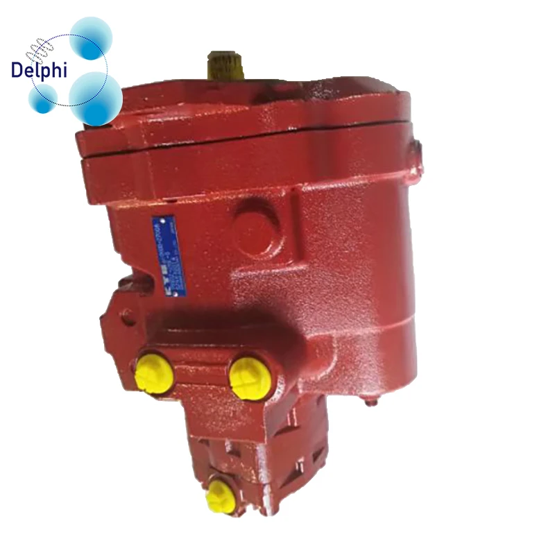
Brand new final drive directly from South Korean manufacturer by North American representative office. Price includes delivery within Canada and the continental USA Complete and fully assembled brand new hydraulic motor and new heavy-duty planetary gearbox, filled with oil, ready to bolt on and go Quality, built in our own factory in South Korea.
We offer the best performing drives for the major OEM brand machines and high-speed! 2-speed capability, works on either side of your machine and has the same location and size of hydraulic ports as your original for ease of making hose connections. If there is any difference in port location, we supply free hoses together with your final drive to make the conversion easy.

For example, Sell points out that the manual for an R-23 Vermeer Twin Rake calls for an 18-gal. reservoir minimum. "Not many tractors have that capacity until you get well over 100 hp," he notes.
"Newer hydraulically-powered rakes, particularly twin rakes, need a hydraulic flow of 20 gal. per minute or more," Sell says. "Some of the older tractors we"ve normally thought of as �rake tractors" just don"t have this kind of hydraulic capacity."
Sell"s neighbor, Don Rodel, Woodville, Wis., wanted to use a Deere 4010 on his Vermeer Twin rake. When he did, though, the hydraulic system got red hot. There wasn"t enough oil in the reservoir and therefore, not enough cooling capacity for the rake. They double-checked the tractor"s hydraulic system to make sure it was operating properly. Then they put Rodel"s 4430 on the rake and its hydraulic system overheated, too.
Sell solved the problem by equipping the tractor with a pto-powered hydraulic pump and mounting a 20-gal. reservoir and cooler directly on the rake hitch. The existing rake hydraulics plug into this system, just like they plugged into the tractor"s hydraulic outlets.
"The 4010 has plenty of horsepower to pull the rake and run the PTO. This protects the 4010"s hydraulic system while providing plenty of hydraulic power to the rake," Sells says.
Sell says the conversion was fairly inexpensive, especially when compared with the cost of having to split a tractor open to rebuild a hydraulic pump worn out because of the intense heat build-up.
In addition to farming, Sell operates B-W Machine, a metalworking and machinery repair shop on his farm. "This is the first conversion of this type I"ve made," he says. "If there"s interest, I could put together a kit, along with instructions for mounting it on the rake. There"s enough hydraulic capacity from this pump that we could also plumb it to handle the lift cylinder on the rake so there"d be no hoses to hook up to the tractor at all."
Rodel now uses a David Brown 995 on the rake. He says there was never a time during the first two cuttings this year that the pump or reservoir got warm enough that you couldn"t touch them.
Add-On Hydraulics Allow Small Tractor To Handle Big Twin Rake HAY & FORAGE HARVESTING Rakes (44) 24-5-41 It doesn"t take a lot of horsepower to power a big hay rake but Bob Sell, Woodville, Wisconsin, says it can take quite a bit of hydraulic capacity.For example, Sell points out that the manual for an R-23 Vermeer Twin Rake calls for an 18-gal. reservoir minimum. "Not many tractors have that capacity until you get well over 100 hp," he notes. "Newer hydraulically-powered rakes, particularly twin rakes, need a hydraulic flow of 20 gal. per minute or more," Sell says. "Some of the older tractors we"ve normally thought of as �rake tractors" just don"t have this kind of hydraulic capacity."Sell"s neighbor, Don Rodel, Woodville, Wis., wanted to use a Deere 4010 on his Vermeer Twin rake. When he did, though, the hydraulic system got red hot. There wasn"t enough oil in the reservoir and therefore, not enough cooling capacity for the rake. They double-checked the tractor"s hydraulic system to make sure it was operating properly. Then they put Rodel"s 4430 on the rake and its hydraulic system overheated, too.Sell solved the problem by equipping the tractor with a pto-powered hydraulic pump and mounting a 20-gal. reservoir and cooler directly on the rake hitch. The existing rake hydraulics plug into this system, just like they plugged into the tractor"s hydraulic outlets. "The 4010 has plenty of horsepower to pull the rake and run the PTO. This protects the 4010"s hydraulic system while providing plenty of hydraulic power to the rake," Sells says. Sell says the conversion was fairly inexpensive, especially when compared with the cost of having to split a tractor open to rebuild a hydraulic pump worn out because of the intense heat build-up. In addition to farming, Sell operates B-W Machine, a metalworking and machinery repair shop on his farm. "This is the first conversion of this type I"ve made," he says. "If there"s interest, I could put together a kit, along with instructions for mounting it on the rake. There"s enough hydraulic capacity from this pump that we could also plumb it to handle the lift cylinder on the rake so there"d be no hoses to hook up to the tractor at all."Rodel now uses a David Brown 995 on the rake. He says there was never a time during the first two cuttings this year that the pump or reservoir got warm enough that you couldn"t touch them. Contact: FARM SHOW Followup, Bob Sell, B-W Machine, 2439 County Road BB, Woodville, Wis. 54028 (ph 715 684-2286).
It"s vital that your skid steer keeps rolling, and your hydraulic motors are the key! In this Shop Talk blog post, we are going to talk about 5 signs that your skid steer hydraulic motors need service. We"ll also talk about what those signs could mean, and how to make sure that the problem is with your final drive hydraulic motor and not some other part of your skid steer.
If your final drive trouble with either the seals or the bearings. Failure of either of these parts can lead to a domino effect of disaster, resulting in a totaled hydraulic motor that needs to be replaced.
If your Worn out bearings can lead to serious damage inside your hydraulic motor. You can see in the picture below an example of the aftermath of a bearing failure. This type of damage really can"t be repaired -- you can"t fix chewed up metal.
If you or an operator notices excessive vibration and noise, it would probably be a good time to get your hydraulic motor serviced. You don"t want to wait until the damage reaches the point that the entire final drive motor has to be replaced.
A final drive that refuses to turn is a problem, but it doesn’t necessarily have to do with your hydraulic motor. If the drive motor isn’t turning, check that the
The same information applies to a skid steer that keeps steering to one side, except that means that it’s just one of the hydraulic motors lacking power. The motor with the problem will be on the same side that the skid steer is veering.
Your hydraulic motors are literally what keeps your skid steer rolling, so if you have any of these signs be sure to get it serviced before the problems develop into something that can’t be repaired. These signs mean there is
is your partner in providing new or remanufactured final drive hydraulic motors from a single mini-excavator to a fleet of heavy equipment. Call today so we can find the right final drive or hydraulic component for you, or check out our online store to.

The information on this page is presented as a courtesy for our web guests. HFI Fluid Power Products does not actively involve itself with hydraulic fluid technical advice. We primarily sell hydraulic adapters, tube and
hose assemblies, as well as components such as valves. Hydraulic fluid is offered to our local customers, but we shy away from sales of hydraulic fluid outside of our local area.
If the information you are looking for is not on this page, we suggest you contact the technical support of one of the US"s larger hydraulic fluid producers, such as Shell Global. Their technical support phone
Overheating ranks No. 2 in the list of most common problems with hydraulic equipment. Unlike leaks, which rank No. 1, the causes of overheating and its remedies are often not well understood by maintenance personnel
Heating of hydraulic fluid in operation is caused by inefficiencies. Inefficiencies result in losses of input power, which are converted to heat. A hydraulic system’s heat load is equal to the total power lost (PL) through inefficiencies and can be expressed as:
If the total input power lost to heat is greater than the heat dissipated, the hydraulic system will eventually overheat. Installed cooling capacity typically ranges between 25 and 40 percent of input power, depending on the type of hydraulic system.
How hot is too hot? Hydraulic fluid temperatures above 180°F (82°C) damage most seal compounds and accelerate degradation of the oil. While the operation of any hydraulic system at temperatures above 180°F should be avoided, fluid temperature is too high when viscosity falls below the optimum value for the hydraulic system’s components. This can occur well below 180°F, depending on the fluid’s viscosity grade.
To achieve stable fluid temperature, a hydraulic system’s capacity to dissipate heat must exceed its heat load. For example, a system with continuous input power of 100 kW and an efficiency of 80 percent needs to be capable of dissipating a heat load of at least 20 kW. Assuming this system has a designed cooling capacity of 25 kW, anything that increases heat load above 25 kW or reduces the cooling system’s capacity below 25 kW will cause the system to overheat.
Consider this example. I was recently asked to investigate and solve an overheating problem in a mobile application. The hydraulic system was comprised of a diesel-hydraulic power unit, which was being used to power a pipe-cutting saw. The saw was designed for sub-sea use and was connected to the hydraulic power unit on the surface via a 710-foot umbilical. The operating requirements for the saw were 24 GPM at 3,000 PSI.
The hydraulic power unit had a continuous power rating of 37 kW and was fitted with an air-blast heat exchanger. The exchanger was capable of dissipating 10 kW of heat under ambient conditions or 27 percent of available input power (10/37 x 100 = 27). The performance of all cooling circuit components were checked and found to be operating within design limits.
At this point it, was clear that the overheating problem was being caused by excessive heat load. Concerned about the length of the umbilical, I calculated its pressure drop. The theoretical pressure drop across 710 feet of ¾-inch pressure hose at 24 GPM is 800 PSI. The pressure drop across the same length of 1-inch return hose is 200 PSI. The theoretical heat load produced by the pressure drop across the umbilical of 1,000 PSI (800 + 200 = 1,000) was 10.35 kW. This meant that the heat load of the umbilical was 0.35 kW more than the heat dissipation capacity of the hydraulic system’s heat exchanger. This, when combined with the system’s normal heat load (inefficiencies) was causing the hydraulic system to overheat.
Hydraulic systems dissipate heat through the reservoir. Therefore, check the reservoir fluid level and if low, fill to the correct level. Check that there are no obstructions to airflow around the reservoir, such as a buildup of dirt or debris.
Inspect the heat exchanger and ensure that the core is not blocked. The ability of the heat exchanger to dissipate heat is dependent on the flow-rate and temperature of both the hydraulic fluid and the cooling air or water circulating through the exchanger. Check the performance of all cooling circuit components and replace as necessary.
An infrared thermometer can be used to check the performance of a heat exchanger, provided the design flow-rate of hydraulic fluid through the exchanger is known. To do this, measure the temperature of the oil entering and exiting the exchanger and substitute the values in the following formula:
A common cause of heat generation in closed center circuits is the setting of relief valves below, or too close to, the pressure setting of the variable-displacement pump’s pressure compensator. This prevents system pressure from reaching the setting of the pressure compensator. Instead of pump displacement reducing to zero, the pump continues to produce flow, which passes over the relief valve, generating heat. To prevent this problem in closed center circuits, the pressure setting of the relief valve(s) should be 250 PSI above the pressure setting of the pump’s pressure compensator (Figure 1).
Continuing to operate a hydraulic system when the fluid is over-temperature is similar to operating an internal combustion engine with high coolant temperature. Damage is guaranteed. Therefore, whenever a hydraulic system starts to overheat, shut it down, identify the cause and fix it.

Every hydraulic pump makes some noise. If all is well with a pump, then this noise stays more or less the same. However, if something goes wrong with the pump or its connected system parts, then you may start to hear sounds that you haven"t heard before.
The fluid that flows through your system needs to move at a smooth and even rate. The pump has to deliver the fluid at a specific flow for things to work.
If something prevents the fluid from achieving and maintaining its optimum flow, then your pump may start to make unusual noises. For example, you may hear a high-pitched whine coming from the pump. This can be a constant or intermittent sound.
If your pump whines constantly, then you may have a cavitation problem. Here, the pump can"t deliver its fluid at the right volume or rate. There isn"t enough fluid coming through the pump"s suction line.
In some cases, this is a sign that your pump"s motor is on the wrong setting. So, the pump itself is working at the wrong speed to create the right flow.
A hydraulic pump might get noisy if one of its parts or connections has a problem. A faulty or failing pressure control, bearing, valve, seal, or coupling can make a noise you haven"t heard before.
In some cases, you may hear vibrating clunks as your pump works if you have a problem with a connecting pipe. A loose seal or connector might allow the pipe to move. It then passes vibrations along to the pump itself.
While some noise problems are easy to fix, some are a sign that your pump is close to the end of its working life. Sometimes, this is due to natural wear, usage, and age. However, in some cases, minor problems cause more widespread damage if you don"t fix them quickly.
For example, if you"ve had cavitation problems for a while, then your system may not have been getting the lubrication it needs; it may have overheated regularly. Even if you fix the cavitation issue, you may be left with a damaged pump that needs a more significant repair, rebuild, or replacement.
So, while new sounds or an increase in operating noise don"t necessarily mean that you have a serious pump problem, you should investigate any unusual noise. Typically, this is a sign that something isn"t working right.
A minor problem in your system could go on to cause significant damage. For an expert diagnosis, contact Quad Fluid Dynamics, Inc. Ourhydraulic pump repair and rebuild servicewill get your pump running smoothly and efficiently again.

When a hydraulic system stops working as intended, whether it is due to a major leak or a failing pump, it can bring productivity to a grinding halt (both literally and figuratively). The process of tracking down the source of the problem involves troubleshooting, which takes considerable skill, experience, and common sense. However, there are some valid guidelines and good hints to help with the process.
The first step in effective troubleshooting is making sure you understand what the problem is — and this can involve asking quite a few questions. If someone says, for example, “The pump is vibrating really bad” then you need to delve a bit deeper with questions, such as:
There are certain problems commonly prevent hydraulic systems from working properly, such as an inoperative system or overheating hydraulic fluid. What follows are some troubleshooting tips for typical issues that arise in hydraulic systems.
If the hydraulic system is inoperative, there are several things that can be checked. Verify the hydraulic fluid levels and keep in mind that leaks can lead to significant loss of hydraulic fluid. Take a look at the hydraulic filters, because if they are dirty or clogged badly enough, it can seriously impact performance. Check for restrictions in the hydraulic lines; restrictions often take the form of a collapsed or clogged line.
Make sure there are no air leaks in the pump suction line. Also inspect the pump itself; if it is worn, dirty, or out of alignment, it will affect system performance. The pump drive can be a source of issues if it the belts or couplings are slipping or broken. It may be time to replace some components; as they begin to wear, it can lead to internal leakage. It is also a good idea to make sure that the unit is operating within its maximum load limits.
When a hydraulic system begins working more slowly than normal, one of the causes can be hydraulic fluid that is too thick, which may be due to cold temperatures or the use of an
If the system is operating in an erratic, unpredictable manner, the most common causes are air trapped in the system, hydraulic fluid that is too cold (which means the equipment needs an opportunity to warm up before use), and damaged internal components such as bearings and gears.
Another common issue with hydraulic systems is excessive/abnormal noise or vibration. If it is the pump that is noisy, then check that the oil level is sufficient, the correct type of fluid is being used, and that the oil is not foamy. If the oil is foamy, that points to air in the fluid which can lead to cavitation and expensive damage. It is also wise to verify that the inlet screen and suction line are not plugged. For both pumps and hydraulic motors, there can also be internal issues, namely worn or misaligned bearings. And do not forget to make sure that the couplings are secure and tight. Keep in mind that pipes and pipe clamps can vibrate if they are not secured properly.
Excessive heat is never a good sign in a hydraulic system and often leads to a system working at sub-optimal levels. One of the purposes of hydraulic fluid is to dissipate generated heat, but the system should not be generating enough heat to cause the fluid to reach high temperatures.
There can be a host of causes behind hot hydraulic fluid, starting with contaminated hydraulic fluid or fluid levels that are too low. There may be oil passing through the relief valve for too long at a time; in this case, the control valve should be set to neutral when it is not in use. Worn out components within the system can also lead to excessive temperatures due to internal leakage.
If there are restrictions in the line or dirty filters, hot hydraulic fluid will result. If hydraulic fluid viscosity is too low, it can lead to overheating as well. Finally, there may be a need to make sure that the oil cooler is functioning correctly and that the key components are clean enough for heat to radiate away from them.
We have discussed low viscosity as a symptom, but it also qualifies as its own problem. When trying to determine why the fluid is not as viscous as it should be, the three things that need to be checked are damage to the oil (often from extreme temperatures or aging), use of the wrong type of hydraulic oil, or the presence of water in the hydraulic fluid. In all three cases, the system will need to be flushed and the oil replaced.
Having no flow within the hydraulic system is a serious issue that can have several different sources. The first step is to determine exactly where the fluid flow stops, such as failure of the pump to receive fluid at the inlet (usually the result of a clogged line or dirty strainers) or a failure for fluid to exit the outlet, which could be due to a pump motor that needs replacing, a sheared coupling between the pump and drive, or a pump/drive failure. It would also be a good idea to make sure the pump rotation is set correctly and the directional valves are in the correct position. The most expensive problem would be a damaged pump that needs to be replaced or repaired.
The first step in troubleshooting is to gather as much information about the problem as possible and then pull the hydraulic schematics for the system. From there, you basically follow a process of elimination until the root of the problem is uncovered. Something else to keep in mind with regard to troubleshooting, however, is that once you have tracked down the source of a problem, it may lead you to yet another problem that will need some troubleshooting. Getting your hydraulic system back in working order can be a time consuming process.
For example, you may uncover that the cause of overheating hydraulic fluid is low viscosity — but why is the fluid insufficiently viscous? The troubleshooting process is not over until that issue is uncovered. Take, as another example, the case of a pump whose internal components have worn out and affected overall system performance — why did the components prematurely wear? It may be a cause of misalignment, insufficient lubrication, or contaminated fluid. A good hydraulics technician will not just track down and address the problem, but will keep troubleshooting to make sure that the problem does not happen again.
At MAC Hydraulics, we understand the importance of having a functional, efficient hydraulic system. We know that any downtime costs money and time that your company simply does not have to spare. That is why we offer comprehensive hydraulic services that include 24-hour emergency on-site troubleshooting and repair services. Our team of experienced hydraulics experts can work on motors, pumps, valves, cylinders, and systems. We serve a wide range of industries, including everything from paper and pulp processing to aerospace to construction equipment. When complex repairs are called for, we have a full machining center and certified welders. We also offer customized maintenance plans tailored to your needs and your equipment.


 8613371530291