
vfd hydraulic pump factory

A hydraulic power unit (HPU) is a common product that IFP supplies to its customers for all types of hydraulic applications. Most customers order their HPUs with standard electric motors and across-the-line motor starters. These electric motors spin at a constant RPM. Because the electric motor spins at a constant RPM, the hydraulic pump coupled to the motor is constantly flowing oil and is likely wasting energy in between system operations.
By allowing the VFD controlled HPU to match the system pressure and flow requirements by varying the pump speed, there are several other advantages to using these VFD controlled HPU systems. By reducing energy put into the system, less heat is generated that has to be dissipated by the system. There are typically noise reductions with VFD controlled HPUs. With reduced heat and reduced system shock, this typically leads to longer component life depending on the load cycle. Hi-lo systems can now be completed with just one fixed displacement hydraulic pump. By over-speeding the pump for extra volumes of fluid, the VFD controlled system does not need a low pressure/high flow pump along with the high pressure/low flow pump. Charging an accumulator can become more efficient as well. Once the accumulator is charged, the VFD controlled HPU can slow down the flow output of the hydraulic pump and maintain the system. Unloading the pump for accumulator charging is typically done with extra valves and consuming unnecessary energy. Overall costs of hydraulic systems can be reduced because smaller hydraulic pumps can be used, less valves are required, less or no cooling for heat dissipation, and smaller reservoirs can be used.
The applications are endless for VFD controlled HPU systems. These systems can be used on anything from a simple filter and lubrication system to extremely complex test stands and presses. With increased efficiency and control, VFD controlled HPU systems will become more common in industry.
For more information on how you can utilize Drives and VFD controlled HPUs, please contact us here to receive a personalized contact by an IFP Application Engineer:

By using variable speed drive technology, instant savings can be realized. By automatically adapting the pump’s speed to match changes in demand, variable speed drives are the perfect addition to many hydraulic systems.
An example of energy-saving tests run by Parker on a hydraulic press system clearly shows that substantial savings on energy are possible using a variable speed drive to reduce motor speed during parts of the machine cycle with low flow demand. Plus, by over-speeding a pump at times of low-pressure demand, a second pump could be eliminated.
Few competing companies can claim the expertise in both hydraulics and electronic drives that Parker brings to the table. With many sizes and styles of pumps and HPUs, and VFDs ranging from fractional to 2000 HP, few applications are out of Parker"s range. To save time and expense, multiple pre-configured VFD programs are available, covering applications like P (system pressure) control, Q (pump flow) control, and Hi/Lo control.

In the current economy everyone has been feeling the pinch. ASI Hydraulics has been taking notes and has noticed the need for a “green” solution to powering the machinery that is required to run an efficient process. The need for a hydraulic power source that can effectively cut costs and endure for the long haul has finally be brought to the table and will be here to stay.
A Variable Frequency Drive (VFD) is a versatile piece of machinery that can be used in a wide variety of applications. They can be used in pumps, motors, conveyors, air handlers, fans, and more. Anything that needs a varying speed or acceleration can be handled by a VFD.
Think of it like this: a VFD is similar to your foot on the gas pedal of your car. Your foot controls the acceleration and deceleration of your vehicle, which, in turn, varies the speed of the vehicle based on your needs. A VFD does that as well with whatever application it’s connected to. It will slow, stop, start, accelerate, and decelerate a system based on the needs of that system, function, or application.
While there are other ways to do this, a VFD is one of the most efficient ways to adjust speed and torque limit of a system. A VFD is able to better control the starting current of a system, which puts less wear on the motor. This can extend your motor’s life and reduce necessary maintenance (more on this later). The lower power demand that a VFD requires can also reduce your overall power usage.
VFD panels allow for overall increased control of acceleration and speed including easier/lower start speeds, programmable controllers, remote adjustment options, and improved stopping. Smoother VFD stopping mechanisms can reduce wear on mechanical components of the system and make processes safer for industrial and manufacturing applications.
Oftentimes businesses find that replacing or installing a VFD system as opposed to other systems can reduce the space the panel/drive takes up because they use fewer components. VFD drives don’t require a reverse starter, and many can eliminate the need for other equipment like hydraulic pumps and gearboxes.
Control valves in hydraulic pumps can also become sticky and/or suffer from control valve hysteresis. These downsides are eliminated with the use of a VFD panel. VFD drives are faster and more responsive than hydraulic pumps as well.
The reduced load that a VFD offers compared to a hydraulic pump system can also elongate the lifespan of your overall system as a result of less wear.
VFD panels can greatly increase your energy efficiency. They lower the necessary power demand on start, reduce overall power usage, and generally improve energy efficiency of your system.
However, it is worth noting that the scale of the energy efficiency a VFD panel or system will provide depends on your particular application, industry, uses, and more. You can ask us any question about how you can expect your energy efficiency to change with the use/installation of a VFD panel or system.
VFDs reduce energy waste by smoothly controlling speed and only using the energy it requires instead of energy/power overuse that can occur with other speed control systems.
Perhaps the most obvious would be connected to the energy efficiency of a VFD panel. Reduced power use and/or energy consumption can reduce your energy spending.
The lowered maintenance requirements and fewer components of a VFD system can also reduce expenses related to upkeep of the system. Longer motor life and less wear on components can also reduce costs associated with this system.
Various states also offer potential financial rebates for VFD installation, which can reduce your overall costs and give you the long term benefits of VFD panels.
VFD benefits range from energy efficiency to prolonged life to noise reduction. They’re also excellent for their versatility and their ability to be customized for each business and each application.

Hydraulic pumps are NOT the same as water pumps! they are Positive Displacement pumps, not centrifugal. They do indeed need high starting torque and in fact a centrifugal pump is exactly the opposite. DO NOT use the "Pump Control" macros in a VFD for a hydraulic pump, it will not work. But it can be done, just be sure to use a "vector" drive so that you can get full motor torque at start-up and use the "Constant Torque" output pattern.
But why are you thinking of putting a VFD on a Hydraulic pump anyway? Lowering the speed may not give you the performance you are thinking of. Don"t get me wrong, it"s done all the time because running the pump slower when you don"t need full flow does save a little energy compared to full speed and a recirc. / throttling valve, and it is also a lot quieter. But at really slow speeds you can run into HP problems and have to have the valve control there anyway. So if you are going to spend a lot of time running at very low flow rates, you might want to rethink the cost of adding the VFD.

Despite ominous predictions in the ‘80s and ‘90s, hydraulics being completely replaced by electrical drives did not occur, and fluid power still plays an important role in modern drive technology. Moreover, it is impossible to imagine many fields of industry working without hydraulic drives. The enormous power density makes hydraulic drives irreplaceable when large forces and high torques are required. Over the last 30 years, “traditional” hydraulics has evolved into electro-hydraulics, where the use of electronics and closed-loop controls has become an industrial standard. For years it was common to depict hydraulics as “strong, but stupid.” Today this reputation no longer exists; hydraulics is not only strong, but also “intelligent.” Modern fluid power drives are perfect examples of integrated mechatronic devices.
Ongoing competition with electrical drives and ever-increasing requirements of performance and energy efficiency have led the hydraulic drive industry to new and more advanced system solutions.
The power control of electro-hydraulic drives typically uses resistive or volumetric control. In resistive control, the system is controlled by a valve, usually a proportional device, to throttle oil flow delivered from a power-supply source. In volumetric control, flow is controlled by adjusting the displacement of a pump or by directly changing the drive speed of a fixed or variable displacement pump. Resistive control possesses excellent dynamic characteristics, however it exhibits poor energy efficiency. Significant power losses occur due to dissipation in the control valve. This is, in effect, hydraulic resistance.
Rising costs of energy and increased awareness of environment issues has resulted in new trends in drive systems. Over the last two decades, improving electro-hydraulic efficiency was a main goal of many companies and research institutes. Given advances in drive technology and closed-loop control, the resistive throttling method is being replaced more often by more efficient volumetric control using speed variable pump systems.
Using Variable Frequency Drives (VFDs) with hydraulic power units can also lower average noise emissions, as the pump speed is reduced during partial-load operations, such as pressure holding or idling. The average sound level can be lowered by as much as 10-20 dB(A), improving environmental working conditions.
The combination of advanced electric-drive technology and hydraulics opens a new chapter in electro-hydraulic drive systems. Machine builders can now benefit from the traditional hydraulic characteristics of robustness and power density, and additionally benefit from the well-known advantages of electrical drives: inherent drive “intelligence” and ease of integration with factory automation systems.
This changing landscape of hydraulic drives pushes fluid power specialists to quickly adapt to using variable speed pump drives. For many engineers, this may not be an easy step. Optimum utilization of variable speed pump drives requires, in many cases, additional system design considerations and modifications to a hydraulic system design. Fluid power engineers need to understand the distinctive features of VFDs and the requirements of the production process being driven. This will define the critical points for the electric and hydraulic elements. The goal of the system is to meet the requirements of dynamics and accuracy, but also keep the focus on overall energy efficiency. When applying a VFD-driven pump, using a conventional induction motor or a permanent magnet servomotor (PMM), the dynamic behavior will differ from a traditional system using a constant speed pump drive and throttling control valve.
Systems using variable speed pump drives can use a number of different design solutions. The selection of the design solution depends on a number of factors. The type of hydraulic circuit, the required response times and accuracy, the power required, and other factors all come into play when deciding the best drive and circuit design. Dynamic performance and power requirements determine the choice of the motor. For applications requiring the fastest response times and highest accuracies, a PMM may be the best selection. Today this technology is used extensively in plastic injection-molding machines. These drive systems offer extremely high performance and have high productivity rates. Due to their high power density and low drive inertia, PMMs have the highest acceleration capabilities. These high dynamics allow complex machine control tasks, such as direct force, speed, and cylinder position control, to be realized without proportional valves. The main limitation when using PMMs is maximum continuous output power, typically less than 60kW. Power units with higher output power, greater than 60kW, may require multiple PMM-pump groups.
Standard asynchronous induction motors driven with VFDs can be used in higher-power applications, where direct control of high dynamic axes is not required. Using standard induction motors with VFDs, operating in a sensorless vector control mode (no separate motor feedback device required) results in a cost-effective system. However, the system designer should be aware of the limitations of direct control using these drives. The system response times can be long as a result of the high inertia of the induction motor. Variable speed pump drives using standard induction motors with VFDs are used today in the woodworking industry, on press applications, in plastics machinery, heavy industry applications, and machining tool applications where the control task is typically regulating system pressure or flow.
The motor size and drive should be selected based on the pressure-flow-time cycle (p/Q profile) for the application machine. In practice, motors on standard HPUs are often sized on “corner power,” calculated from the maximum pump pressure and flow, and duty cycle is commonly not taken into account. This results in the installation of excess motor HP. If partial load comprises a significant portion of the machine cycle, the excess motor power can be significant. Sizing PMMs for variable speed pump drives should follow methods commonly used in electro-mechanical actuator drives: calculating the root mean square (RMS) value based on the load torque and average drive speed. Once a pump size is determined, the motor torque and speed are calculated from the required pump pressure and flow. Additionally, the dynamic torque requirements for accelerating and decelerating the motor’s rotor and pump inertia need to be added. These calculated values are used to select the proper size drive and motor. Drive sizing and system optimization can be done using specialized tools, such as Bosch Rexroth’s SytronixSize, which allows analyzing p/Q profiles and motor load factors. For a more complex analysis, a numerical simulation can be used to model the system. Dynamic simulations help by providing more insight to the system dynamics, such as pressurization dynamics, and to investigate interactions between the drive and the hydraulic system. Analysis of the performance of closed-loop controls can be done, as well. These dynamic simulations can be carried out using software that includes drive and hydraulics model libraries. Simulation tools, such as Bosch Rexroth’s Simster 3, ITI SimulationX, or MATLAB/Simulink Simscape can be used for these requirements.
Internal gear pumps are characterized by high efficiency, low flow ripple, low mechanical inertia, and high-pressure capability. Due to these characteristics, they are widely used with PMMs on injection-molding machines. The limitations are fixed displacement and limits on the minimum drive speed during pressure-holding operation. Axial piston pumps, either fixed or variable displacement design, have desired properties of high efficiency at low speed, making them ideal for pressure-holding operation. Using a variable displacement pump allows the possibility to lower the motor torque during pressure holding in the machine cycle. This can result in higher system efficiency, since the motor and pump can operate under more desirable operating conditions. Using a high-response variable displacement pump with closed-loop displacement control, such as Rexroth’s DFEn 5000, the pump’s performance can compensate for relatively low dynamics of the VFD drive and motor. The pump displacement control can react a magnitude or more faster than the motor speed control. This is of greater value when used with higher HP drive motors.
It is expected that speed variable pump drives will replace an increasing number of standard motors in hydraulic power units in the future. This change is already utilized by many plastic machinery OEMs and is quickly expanding in press applications. Understanding the principles of variable speed drives and the interaction between hydraulics and electric drives will be key to future fluid power engineering.
Advanced Fluid Systems is proud to offer hydraulic repair services for hydraulic pumps and motors, from gear pumps to vane pumps to the largest radial piston pumps, regardless of brand. Our inventory includes seals, parts and re-manufactured pumps available for immediate shipment.
100HP programmable variable frequency drive (VFD) test system for mineral oil and water glycol fluids that allows us to test pumps with electronic controls.
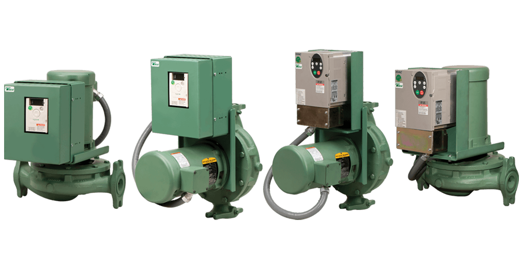
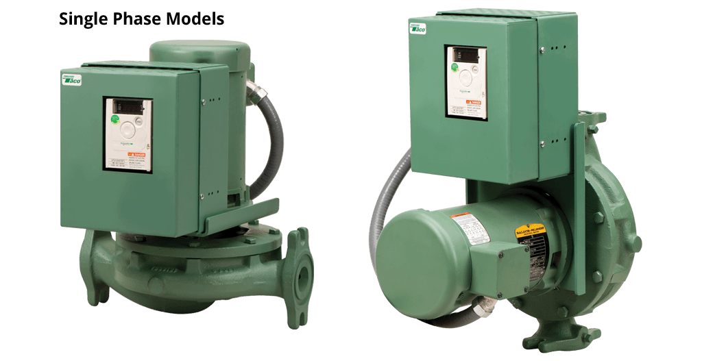
The 1900 VFD Series Close-Coupled In-Line Pumps meet the latest industry standards for hydraulic performance and reliability. The 1900 VFD Series Close-Coupled In-Line Pumps are compact, energy efficient and can be installed anywhere in the piping layout.
Let the variable frequency drive (VFD) on the 1900 VFD Series Close-Coupled In-Line Pump operate your buildings with greater efficiency; using them to control your pumps can significantly reduce energy costs. Most HVAC systems are designed to keep the building cool on the hottest days and warm on the coldest days. Therefore, the HVAC system only needs to work at full capacity on the 10 or so hottest days and the 10 or so coldest days of the year. On the other 345 days, the HVAC system may operate at a reduced capacity. This is where a system with variable frequency drives (VFDs) can be used to match system flow to actual heating and cooling demands. The VFD can reduce the motor speed when full flow is not required, thereby reducing the power required and the electrical energy used.
At NPE2018, both Jomar Corp., Egg Harbor Township, N.J., and Bosch Rexroth Corp., Bethlehem, Pa., introduced new products that provide an educational illustration of the differences between two types of energy-saving variable-speed drives for hydraulic pumps.
The term “servo-hydraulic” has gained currency to describe new generations of plastics machinery that utilize hydraulic pumps but with energy savings and noise reduction closely approaching those obtained with all-electric servo motors and drives. At the same time, popularity has also been growing for aftermarket retrofits of conventional hydraulics with variable-frequency drives (VFDs), another way of saving energy by varying pump speed—even to zero—according to the instantaneous load demand of the system.
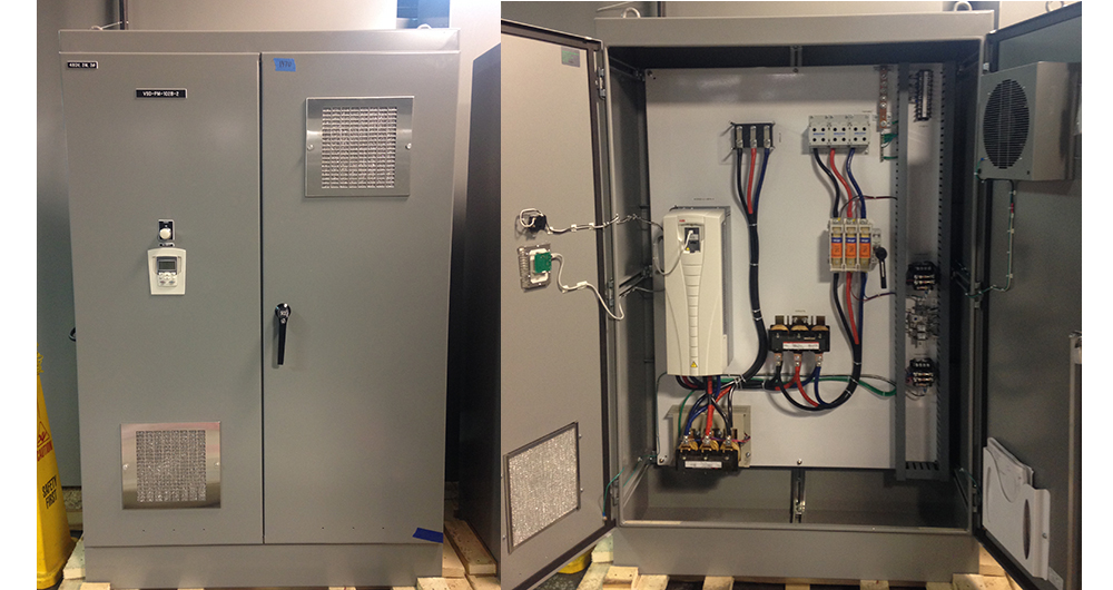
Bosch Rexroth introduced at the show its Sytronix DRn 5020 VFD, aimed specifically for converting variable-displacement hydraulic pumps driven by conventional fixed-speed (1800 rpm) motors to quieter, more energy-efficient variable-speed operation. It reportedly saves up to 75% in electrical energy for systems that have long dwell times; and the average noise reduction is 8 to 10 dBa vs. fixed-speed hydraulic drives. This “intelligent” drive senses the motor torque and pump pressure to calculate the pump displacement, or position of the swash plate, to keep it in the most efficient position for the real-time load requirement. This drive is Industry 4.0 compatible, as it adds operating data collection and digital communications to conventional electric motors and hydraulic pumps that normally do not have these capabilities.
Bosch Rexroth notes that VFDs are considerably less expensive than servo drives, but the firm also points out in a white paper that they provide less tight control over motor speed than servos and have lower dynamic performance—ability to respond and control pressure/velocity changes. VFD drives are thus more suited to steady or slowly changing loads. They also have low-speed limitations and are usable only to 400-500 rpm.
Bosch Rexroth points to an instructive use of both its MSK servo motor and the new Sytronix DRn 5020 on Jomar’s new IntelliDrive injection-blow molding machines. Jomar often refers to these machines as “servo-hydraulic,” but the servo drives only the hydraulic pump for the injection unit. The injection and blowing clamps use a pump with the new VFD. The Jomar IntelliDrive 85S at the show boasted 42% lower energy consumption than a standard model 85S and required a 40% smaller oil tank.

There are some applications where a pump must discharge into a closed system to meet continuously varying demands where a variable speed pump could pay for itself in a short time. But what about water and wastewater systems?
(First, a digression. There is no such thing as a variable speed pump. A pump is a pump. What constitutes variable-speed pumping is a variable-speed motor attached to a pump. A variable frequency drive (VFD) is the best technology these days to produce variable speed. So, I’ll call the pump, VFD and motor together as a variable speed pump.)
The selection of the pumping technology should be based on life cycle costs (plus some other considerations) and depends heavily on the nature of the pumped system. There are essentially two types of systems – those that have floating storage and those that don’t. This makes a big difference in the type of analysis required.
Systems with storage have a significant advantage in pumping in that it is possible to turn the pumps(s) OFF. This storage can refer to an elevated water storage tank or a sewage wet well. If you correctly select the right constant speed pump, you can run it at an efficient operating point to fill the storage tank or drain the wet well and turn it off. I’ve done a lot of calculations along these lines, and constant speed pumping almost always wins.
But as with everything else in life, there are exceptions to the rules. The first exception depends on the shape of the system head curve. Most water, and to a lesser extent, sewage pumping involves a fairly flat system head curve. Water is lifted from one pressure zone to the next higher one or lifted over a drainage divide. It is very difficult to turn down the speed without seriously hurting the efficiency. However, if you are pumping across flat ground, most of the energy is used to overcome friction, and the flow can be adjusted without having as much detrimental effect on efficiency. The friction-dominated case may favor a variable speed pump.
In systems without storage, it’s not possible to turn pumps off, so the pump station must meet the instantaneous demand. This means that during low demands, a constant speed pump would need to run far to the left on its curve and the pump would be pumping at a high head and low efficiency. A variable speed pump would be the clear winner—but not always.
The pump station must meet peak demand with the largest unit out of service. The typical configuration for a small to medium pump station is usually two pumps, with each sized to meet peak demands. But, in most situations, the peak demand rarely occurs, and the one running pump is running at low efficiency, especially during low flow periods.
Is there a better configuration than these two pump solutions? Enrico Creaco and I (Walski and Creaco, 2016) tested a wide range of configurations (see below) over a wide range of flow in a paper we wrote using WaterGEMS to calculate life-cycle energy costs.
As expected, the configuration with two constant speed pumps had the worst life-cycle cost. But surprisingly, the second-worst was the two variable pump setup that pretty much everyone uses. Configurations with three pumps (or for very small systems, two pumps, and a hydropneumatics tank) proved to be better than two variable speed pumps. All the three pump configurations were fairly close to one another in cost. The reason they were so good was that their best efficiency point could be matched fairly well with the most common demands with only one pump running. For those cases, where demands were high, simply turn on the second pump until the demand drops.
A lot depends on the actual flow distribution that the pump station will encounter. If the peak flow is 800 gpm and the average flow is 750 gpm, then any configuration will work well. However, if the peak flow is 800 gpm and the average flow is 200 gpm, then it will be virtually impossible to make the two-pump designers work efficiently.
In an earlier blog (Abusing Affinity, 4 March 2021), I mentioned how the calculations of head and efficiency for variable speed pumps are governed by the pump affinity laws, and sometimes those folks selling VFDs misrepresent the affinity laws to make their product look more beneficial than it really is.
Another issue is the fact that the VFDs themselves introduce a certain amount of inefficiency. They work by breaking up the smooth sine wave of alternating current into pieces and reassembling those pieces in a sine wave with a lower frequency, thus varying the pump speed. The problem is that this reformulated output wave is less than 100% efficient. This loss of efficiency is sometimes called the “parasitic energy demand of the VFD”. VFD salespeople don’t like to talk about this, and if you ask them for data about VFD efficiency, they will only provide data at 100% of full speed, which is not the case you’re looking for, or respond along the lines of.” Hey, do you think the Chiefs will win the Super Bowl next year?”
How do you decide on the best configuration for your pump station? I’ve been trying for years to come up with some rules-of-thumb to decide on the best configuration, and the best I could come up with are the paragraphs above.
What you need to do as a conscientious engineer is try many designs to arrive at the best pump selection. The most tedious step in a good evaluation is calculating the life-cycle energy cost because the pumps must work over a range of conditions. In my early days, I did these calculations manually, and you needed to make a lot of simplifications to make the effort feasible. Later, I graduated to spreadsheet calculations, but that still didn’t capture all the hydraulic and cost variability. Now, if you start with a well-calibrated model, WaterGEMS and WaterCAD can give you the results you need with a few mouse clicks.
Walski, T. and Creaco, E., 2016, “Selection of Pumping Configuration for Closed Water Distribution Systems”,Journal of Water Resources Planning and Management,142(6), DOI: 10.1061/(ASCE)WR.1943-5452.0000635.

Siemens’ Sinamics servopump is built on standard components such as the Sinamics S120 drive platform and distributed I/O, and offers users increased machine output and reduced energy costs by up to 50%.
With any fluid power system, efficiency is always top of the mind, so components and advanced technology that can improve energy consumption are increasingly necessary. To that end, the NFPA last year commissioned a survey to examine the current and potential use of variable speed drives (VSDs) with hydraulic pumps.
Not surprisingly, the overall results showed that respondents believe that the use of VSDs in hydraulic applications will increase over the next three years. They cited VSDs’ high-energy efficiency, improved reliability and low operating cost as key determining factors in the increase of their use. On the opposite end of the spectrum, when asked what discourages the use of VSDs, respondents pointed toward high acquisition or upfront costs, lack of maintenance and after-sales support for VSD technology, and lack of design expertise in their use.
The four main manufacturers of variable speed drives in the U.S. include Eaton, Parker Hannifin, Siemens and Bosch Rexroth. Here, we spoke with representatives from three of those companies—Lyle Meyer, global product manager, Industrial Drives, Eaton Hydraulics; Lou Lambruschi, marketing services and e-business manager, Parker’s Electromechanical and Drives Div.; and Craig Nelson, marketing manager, Drives, Siemens Industry U.S.—to learn how VSDs can change the way hydraulics function in an industrial setting.
Meyer: There are three advantages variable speed drives offer the market— low noise, longer life and higher efficiency. Depending on what a particular customer’s needs are, low-impact noise could be a primary reason to incorporate a VSD into a machine. Eaton’s pumps are capable of running down to zero rotations per minute, so reduced noise in the overall system—and better overall sound quality—are significant features.
Efficiency is a key driver that brought about Eaton’s variable speed drives solution, and there are several market influencers that have led to innovative hydraulic pump and system level technologies—government regulations and energy costs. Energy costs continue to increase over time, and government regulations are continuing to require fewer emissions, both of which have led machine builders to consider more efficient electric motor solutions. If hydraulic pumps cannot operate in the speed ranges needed to complement the wider speed ranges of VSD motors, they can be replaced by electro-mechanical options.
There’s another part about it, too, which is environmental … as well as being “green” on the cost is the environmental impact of being less likely to have hydraulic leaks around your plant. That’s something that everybody really has to keep a big check on because of its environmental impact.
Lambruschi: The biggest advantage tends to be energy savings. Other types of pumps will see increased controllability, quieter operation and potentially longer life. Drives equipped with fieldbus communications allow for local or remote monitoring of the pumping process, allowing access to parameters like pump loading, running time and energy consumption.
There is such an installed base of hydraulics out there. I think most of the new machine users are not even giving it a second thought of going with the new technology. What’s been slower is driving people to retrofit out their existing working system for something that’s better, more efficient, takes up less room, less oil, less noise, and all the other advantages that it provides.
Meyer: Generally, there are three things that are holding people back from adopting VSD technology—perception, cost and system design. Perception is now the main issue preventing customers from adopting VSD technology, whereas the number one issue in the past was overall cost. Machine builders initially thought a VSD solution for a hydraulic system was extremely expensive. Today, it is equally cost-effective to make a system hydraulic variable speed as it is to make it electric. Hydraulic components don’t change, and electrical components have experienced much lower costs in the past five years. Fixed-speed starters used to be the lower cost, but now variable speed drives are generally the same or lower cost as fixed speed.
Lambruschi: In many retrofit applications with known operating cycles, an estimated payback period can be calculated. In actual applications, this has been shown to be less than 12 months. Cost concerns can also be offset by the fact that many power utilities offer rebates or incentives for the purchase of variable speed drives for pumping applications. Also notable is the fact that cost savings are not just achieved by efficiency, but by less obvious factors such as reduced maintenance costs and enhanced pump life.
Meyer: Duty cycle is key to balancing cost with efficiency. Pumps are capable of multiple speeds, including zero speeds that allow operators to incorporate VFDs—the building block for smart machine architecture. Before you can start designing machine control, you need components that can handle that level of control. If there are cost increases with a VSD, then they must be paid back on the duty cycle.
Lambruschi: Within pumping applications, we see particularly good growth in the use of drives on hydraulic power units, replacing proportional valves and similar technologies with a more efficient approach. Growth is seen in multiple regions globally, with concentrations in areas where new production facilities are being built or older ones modernized.
Nelson: For us, it’s all about ease of use. We offer this solution with our standard sizes and software. We use the same components that we use for most of our typical servo systems, not just our servopumps, like our Sinamics S120 drives, 1FK7 motors and 1PH8 motors.
Lambruschi: Pre-programmed pump application macros and pump-specific parameters, as well as environmental features like conformal coated PC boards, make Parker drives more user-friendly and suited to the tough environments that pumping applications are often a part of. Larger drives used on higher power pumps are constructed with field replaceable power modules, allowing for quick and easy maintenance and minimal downtime in the event of failure. Parker is also uniquely positioned to be a complete system provider, being a manufacturer of pumps, hydraulics, and fluid handling components in addition to variable speed drives.
Meyer: Eaton’s biggest differentiator is low speed—our pump products have been tested down to zero speed. Eaton’s pump products are capable of operating at speeds that are as low as or lower than competitive offerings.
In the past, Eaton pumps or competitive offerings could simply be turned off; however, that function added some complexity to the circuitry. A pump capable of running at zero rpm takes a lot of complexity out of the circuit, in terms of holding pressure. Eaton’s zero-speed capability decreases system complexity and further enables the machine designer to flexibly design the system.


 8613371530291