
vickers hydraulic pump pressure adjustment made in china

The wide-range fixed and variable displacements of Eaton PVX & PFX Series piston pumps make them ideal for use with primary metal power units, test stands, mixer drives and more. They come in a robust housing enclosure and are available with displacements from 66 cc to 250 cc (4.03 to 15.26 cu in) at operating pressures up to 350 bar (5,075 psi) for broader application.
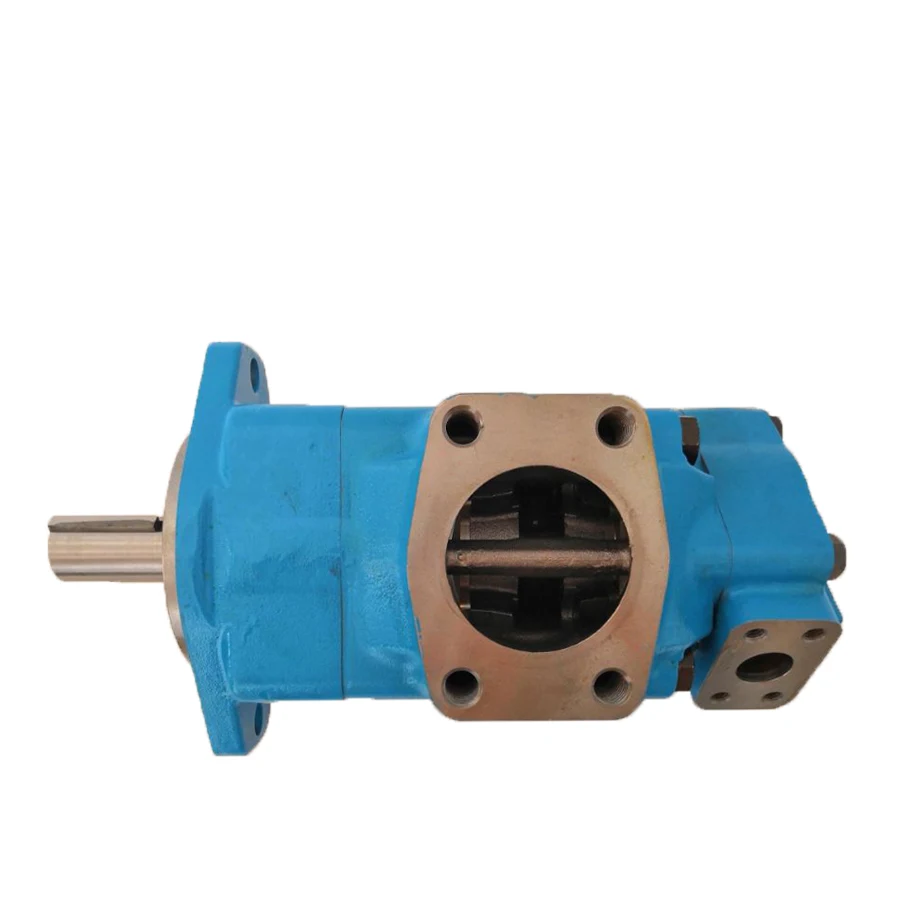
HEASH TECHNICAL B.V. specialised in the sale of Eaton pumps and motors across their entire range. We supply Eaton Vickers PVXS and PFXS all sizes, as PVXS066, PVXS090, PVXS130, PVXS180, PVXS250, PFXS066, PFXS090, PFXS130, PFXS180, PFXS250. for other Eaton Vicksers pumps as PVH, PVM, PVQ and valves as KBHDG, KDG4V, KFDG, KBDG, KSDG..., please don’t hesitate to contract with us if u have any interested in our sale.

Hydraulic pumps are used in many different industries, such as construction and agriculture. They’re used to push liquids, slurries and gases though a process where they change direction and speed. This is done by changing the pressure that a fluid exerts on a hydraulic pump or cylinder. Since hydraulic motors are used for working fluids with lots of inertia properties, their control is very critical. A hydraulic system does not operate properly if you force it to do too much work unless there is enough room for the pump output pressure to drop below its required value. By adjusting the output pressure in this way you can make sure that the system works at maximum efficiency therefore helping prevent breakdowns.
A hydraulic pump is a machine used to move fluid. The fluid is usually hydraulic oil or water, but it can also be other types of fluid. When the hydraulic pump is working, the pressure in the fluid inside the pump is higher than the atmospheric pressure. This means that the fluid inside the pump is under a lot of pressure and can push things around. If you want to use the pump to move something, you need to make sure that the pressure in the fluid is at the right level.
The pressure in a hydraulic system can be adjusted using a valve called a relief valve. Relief valves are usually found on the outlet of a hydraulic system. When you operate a relief valve, you are lowering the pressure in the system by releasing some of the pressure from the system. This reduces the amount of force that needs to be used to move something and makes it easier for you to operate the pump.
There are different ways to adjust pressure in a hydraulic system. One way is to use an adjusting screw on a relief valve. Another way is to use an accumulator tank (a container that holds hydraulic oil). You can open or close the accumulator tank using hand levers or an electrical controller.
A hydraulic pump is a mechanical device used to transfer fluid from one container to another. It is important to adjust the pressure of the hydraulic pump in order to maintain consistent flow rates and pressure levels.
One of the most common reasons for needing to adjust the output pressure of a hydraulic pump is when the fluid level in the reservoir falls below the pump’s operating level. In some cases, the pump may operate at a higher pressure than necessary, leading to wear and tear on components.
Adjust the output pressure of a hydraulic pump is an important step to take, especially when it comes to your lawnmower. Even if you know what type of motor you own, you have to make sure that your engine will be able to work with that pressure. The mechanical components and settings required for adjusting your engine may differ depending on the model you own but most models have similar things in common.
Adjusting the output pressure of a hydraulic pump can be a hassle, but it’s not too difficult. The pump pressure adjusting screw is usually located on the front or back of the pump. To adjust the output pressure, first locate the screw. Once you find the screw, turn it until you get the desired output pressure. You can find a chart to help you calculate the output pressure of your hydraulic pump by visiting our Equipment and Tools section.
Fill the tanks with hydraulic oil. Before you adjust anything, fill the tank with the appropriate hydraulic fluid based on your application’s specifications. If you’re unsure what type of fluid your application requires, contact an equipment dealer or refer to your vehicle’s owner’s manual for information.
When the hydraulic pump is used, the pressure in the system will increase. This pressure is necessary to operate the pump and can be dangerous if not released. To release the pressure, open the valve on the pump.
2: Remove the cap on the pump discharge line, turn the adjustment screw until the desired output pressure is reached, replace the cap and tighten the locknut.
When you are finished adjusting the output pressure, turn the adjusting screw one more time in the same direction to lock it in place. Be sure to read and follow the instructions that came with your hydraulic pump before making any adjustments.
Adjusting a hydraulic pump’s output pressure is an important task for ensuring proper performance of your machine. When you are finished adjusting the output pressure, turn the adjusting screw one more time in the same direction to lock it in place. Be sure to read and follow the instructions that came with your hydraulic pump before making any adjustments.
If the hydraulic pump is not providing the desired output pressure, it may be necessary to adjust the output pressure. This can be done by adjusting the compression or output valves.
To adjust the compression valve, remove the cap and turn the adjustment screw until the desired output pressure is reached. To adjust the output valve, turn it clockwise or counterclockwise to change the output pressure.
Adjusting a hydraulic pump output pressure can help optimize its performance and prolong the life of the pump. By properly adjusting the output pressure, operators can ensure that the hydraulic system is functioning at its best while minimizing wear and tear.

All of Hytec’s electric/hydraulic pumps are two-stage, continuous pressure (demand) pumps that contain all the necessary controls and circuitry for powering any single- or double-acting, continuous pressure workholding system. They contain a pressure switch and pressure regulator, and each is infinitely adjustable throughout the operating pressure range of 1,000 to 5,000 psi. An internal safety relief valve prevents possible damage from exceeding the maximum rated pressure.
The first stage provides high flow at low pressure to rapidly extend clamps and cylinders. The second stage piston pump builds and maintains pressure in the system at a preset level.
The pumps’ electrical controls include a RUN/JOG switch. When the pump is started in the RUN mode, it automatically starts and runs any time the pressure switch indicates the need for oil. When pressure builds to the switch setting, the pump stops until the next demand for oil lowers the pressure, causing the switch to start the pump again. The pump continues to cycle in this manner without operator intervention.
In the JOG mode, useful for set up and special applications, the pump will run only when the operator activates and holds the start switch. When released, the pump will stop immediately. If the pump builds pressure to the pressure switch setting, it will also stop. The pump cannot be forced to run after the pressure switch setting has been reached in either the RUN or the JOG mode.
Pumps having thermal overload protection have an integral “electrical shut-down” circuit which prevents the pump from restarting without manual intervention after either thermal overload or electrical service interruption. Motor electrical specifications are listed for each pump. For voltages and frequencies not listed, contact Hytec for more information.
√ Drive shaft-there are many forms to choose from as needed. There is a high-strength swash plate in the variable pump and variable motor, which can prevent deformation under large load.
√ There is a charge pump-cycloid fixed rotor pump in the main pump. There are several displacements to choose from to meet various requirements, all of which are made of cast iron.
√ Hydraulic servo control-can reduce the control pressure, the operation force is small, the large diameter servo cylinder piston can keep the position of the swash plate unchanged and play a buffering role.


 8613371530291