
vickers pvb15 hydraulic pump free sample

61 hydraulic pump parts for vickers pvb15 products are offered for sale by suppliers on Alibaba.comAbout 67% % of these are hydraulic pumps, 19%% are construction machinery parts, and 9%% are other hydraulic parts.
A wide variety of hydraulic pump parts for vickers pvb15 options are available to you, You can also choose from piston pump, gear pump and vane pump hydraulic pump parts for vickers pvb15,as well as from 1 year, 6 months, and 3 months hydraulic pump parts for vickers pvb15,And whether hydraulic pump parts for vickers pvb15 is fittings, {2}, or {3}.
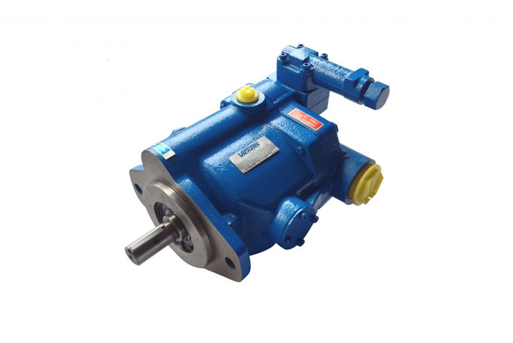
Both fixed and variable displacement models make up this range of axial piston pumps. Their high performance ratings and efficiency are achieved with a variety of hydraulic fluids. Fixed displacement models are noted for their volumetric and mechanical efficiency. Variable displacement models can closely match pressure and/or flow demand with a variety of control options as follows:
Replace your old Vickers PVB with the Continental HPV range of piston pumps. Output flow sizes are equal to the Vickers pumps including the 6, 10, 15, 20 and 29 gallons per minute @ 1750 RPM units. Contact us with your Vickers PVB part number for a direct Continental hydraulics replacement pump.
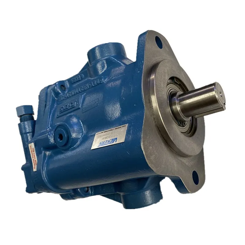
Pressure: High Pressure;Standard or Nonstandard: Standard;Power: Hydraulic;Structure: hydraulic part;Brand Name: Vickers;Model Number: PVB15, PVB20, PVB29;
Pressure: High Pressure;Standard or Nonstandard: Standard;Power: Hydraulic;Structure: hydraulic part;Brand Name: Vickers;Model Number: PVB5, PVB6, PVB10;
Product Brief: Product DescriptionVicker PVE21 Hydraulic pump spare partsVicker series A37 A40 A56 A70 A145 A3H100 PVE12 19 21 hydraulicPump parts all on saleKYBPSVD2, MSG,JMVLiebherr LPVD
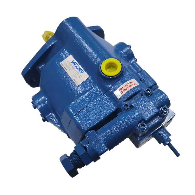
Product Brief: Vickers PVB5/6/10/15/20/29/45 Hydraulic Piston Pump Spare PartsApplication:Construction Machinery,Agricultural Machinery,Coal Mine Machinery.VICKERS PVB5/6/10/15/20/29/45 All models for hydraulic
Product Brief: 1.F3-Viton seals Omit if not required 2.Series designation 3.Flow -Shaft end pump Flow (Usgpm) at 1200rpm and 6.9 bar Series Usgpm Geometric displacement 25**V 10 12 14 15 17 19 21 32.5(1.98) 39(2.38
Product Brief: Polaris specialize in manufacturing OEM hydraulic pumps (gear pump,vane pump,plunger pump)and brand pump replacement parts, such as Parker,Eaton,Danfoss,vickers,Caterpillar,Rexroth Other replacement
Product Brief: Our group produce replacement hydraulic Hydraulic Eaton Vickers PVQ variable axial piston pump, PVQ10. PVQ13, PVQ20, PVQ32 model below: PVQ10-A2L-SS1S-20-C21-12, PVQ10-A2L-SS1S-20-C21-12,
Product Brief: Vickers PVE19/21 Hydraulic Piston Pump Spare Parts Model number:PVE19/21 Application:Main Pump of Cropper or Other Construction Machinery. VICHERS PVE19/21 We can also supply: Cylinder Blocks (Barrels
Product Brief: These cost effective pumps provide volumetric efficiencies of more than 90% and sound levels as low as 62 dB(A) with operating pressures to 207 bar(3000psi).
Product Brief: Low noise and long life Ease of repair and serviceability Wide range of applications Compact for limited spac VICKERS SPV Series: Item Spear parts Quantity 1 Valve Plate(L/R) 1 2 Snap Ping 1 3 Spacer
Product Brief: HKH is manufacturing full series of replacement Vickers piston pumps parts for that remanufacturing and repairing pumps in construction machinery and industry application. All spare parts of Vickers
Product Brief: We are excel at Vickers Vane pump, but our products are the replacements, V series, VQ series, SQP series vane pumps, In addition, Denison vane pump and Atos vane pumps, some of them we are design
Product Brief: Our V & VQ vane pump can be highly interchangeable to the original ones.Now we have 20V, 25V, 35V, 45V, 20VQ, 25VQ, 35VQ, 45VQ, 4535V, 3525V, 4520V, 3520V, 2520V, 4535VQ, 3525VQ, 4520VQ, 3520VQ,
Product Brief: Cartridge kits for DENISON T6C/T6D/T6E /T6CC/T6DC/ T6ED,T6DCC,ETC... REXROTH PVQ series single pumps and PVQ series, VICKERS 20V/25V/35V/ 45V/50V 2520V/3520V/3525V/4520V/4525V/4535V, YUKEN PV2R2-65,
Product Brief: our factory produce cartridge kits for vane pump, brand like Denison, Vickers, Tokimec, ATOS, CAT, ect. Models we are showing are 20V, 25V, 35V, 45V, 20VQ, 25VQ, 35VQ, 45VQ and double vane pumps
Product Brief: Vickers 20VQ/25VQ/35VQ/45VQ/20V/25V/35V/45V cartridge kits vane pumps Now you can get full series and different connecting size vickers v & vq series vane pumps from us. We also provide full series
Product Brief: Vickers Vane Pump 20V series Specification: Series Size Delivery Max Pressure(Mpa) Max Speed(rpm) Min Speed(rpm) 20V **20V 2 7.5(0.46) 14 1800 600 3 10(0.61) 4 13(0.79) 21 5 16.5(1.01) 6 19(1.16) 7 23
Product Brief: The Vane pump from our company are produced in accordance with Vickers original designs and can be interchangeable to OEM products. As we use advance manufacture toolings and the best materials,
Product Brief: Ningbo Oilmax can supply a large of the PVE19/TA1919 pump parts,such as : HOUSING TA1919, ROTATING GROUP TA1919 & MFE19,WAFER PLATE L/H, WAFER PLATE R/H, YOKE FOR TA1919SHAFT MAIN TA1919, MAIN CENTRE
Pressure: High Pressure;Standard or Nonstandard: Standard;Power: Hydraulic;Structure: hydraulic part;Brand Name: Vickers;Model Number: PVM018,PVM020,PVM045,PVM050;
Pressure: High Pressure;Standard or Nonstandard: Standard;Power: Hydraulic;Structure: hydraulic part;Brand Name: Vickers;Model Number: PVB38, PVB45, PVB90;
Established in 2010, developing fast in these years, now Shanghai Belle Hydraulic Co., Ltd has been expanding overseas markets to more than 30 countries including USA, Canada, England, Italy, Poland, Russia, Brazil, Peru, Argentina and Southeast Asian countries.
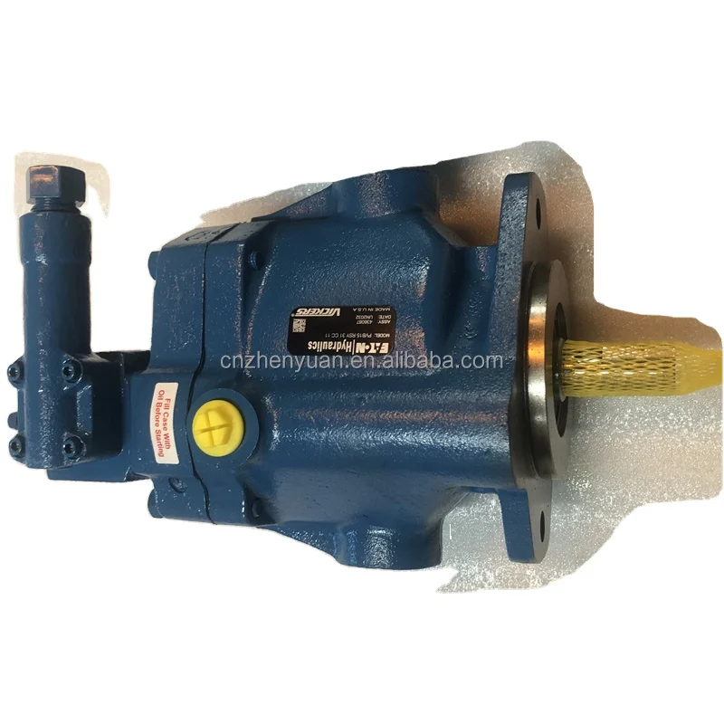
- Basic Characteristics Type . . . . . . . . . . . . . Axial piston pumps Operating pressure . . . . . up to 210 bar (3000 psi) Displacement . . . . . 10,5 to 197,5 cm3/r (0.64 to 12 in3/r) Drive speed . . . . . . . . .up to 3600 r/min
- General Description Both fixed and variable displacement models make up this range of axial piston pumps. Their high performance ratings and efficiencies are achieved with a variety of hydraulic fluids. Fixed displacement models are noted for their volumetric and mechanical efficiencies. Variable displacement models can closely match pressure and/or flow demand with a control selected from: Pressure compensator with or without a remote control facility. Pressure compensator with adjustable displacement control. Load sensing compensator. Mechanical (lever) control. Hand wheel control
Technical data: Input Input Geometric Out flow Speed Pressure KW Geometric Out flow Speed Pressure KWModel displ. LPM rpm bar [hp] Model displ. LPM rpm bar [hp] cm3/r [gpm] [psi] @high cm3/r [gpm] [psi] @high [ in3/rev] @rpm pressure [ in3/rev] @rpm pressure &speed &speed 10,55 18,9 210 13,0 10,55 37,8 210 13,0PVB5 1800 PFB5 3600 [.64] [5] [3000] [17.5] [.64] [10] [3000] [17.5] 13,81 22,7 140 26,1 21,10 68,1 210 26,1PVB6 1800 PFB10 3600 [.084] [6] [2000] [35] [1.294] [18] [3000] [35] 21,1 37,5 210 29,4 42,80 102 172 29,4PVB10 1800 PFB20 3600 [1.29] [10.0] [3000] [39.5] [2.61] [27] [2500] [39.5] 33,0 59,4 141 29,4 94,4 208 210 71,7PVB15 1800 PFB45 2200 [2.01] [15.7] [2000] [39.5] [5.76] [55] [3000] [96.1]
61,6 109,7 140 29,4PVB29 1800 [3.76] [29] [2000] [39.5] 94,5 170,3 210 29,4PVB45 1800 [5.76] [45.0] [3000] [39.5] 197,5 348 210 29,4PVB90 1800 [12.0] [91.9] [3000] [39.5]Basic Characteristics Typical SectionType . . . . . . . . . . . . . Axial piston pumps Variable displacement model with compensator control “C” or “CM”Operating pressure . . . . . up to 210 bar (3000 psi)Displacement . . . . . 10,5 to 197,5 cm3/r (0.64 to 12 in3/r)Drive speed . . . . . . . . . up to 3600 r/min
General DescriptionBoth fixed and variable displacementmodels make up this range of axialpiston pumps. Their high performanceratings and efficiencies are achievedwith a variety of hydraulic fluids. Fixeddisplacement models are noted for theirvolumetric and mechanical efficiencies.Variable displacement models canclosely match pressure and/or flowdemand with a control selected from: Pressure compensator with or without a remote control facility. Pressure compensator with adjustable displacement control. Load sensing compensator. Mechanical (lever) control. Handwheel control
1 Basic models 9 Shaft type 13 Pressure compensator variationsF = Fixed displacement type N = Metric, to DIN/ISO 3019, Part 2 PVB5 to 29 models only:V = Variable displacement type and VDMA 24560, Part 1 G = Remotely adjustable pressure Y = SAE models P*B5 to 15 only. setting. 2 Displacement Omit for 20 thru 90 models Omit when not required.PFB and PVB models: 5 = 10,55 cm3/r (0.64 in3/r) 10 Pump design number 14 Control location10 = 21,10 cm3/r (1.29 in3/r) 10 = PFB20 PVB5 to 15 models with “H”, “M” or “V”20 = 42,80 cm3/r (2.61 in3/r) 30 = PFB10 controls only:PVB models only: 31 = PVB10 and PVB15 L = Left hand, when viewed at shaft 6 = 13,81 cm3/r (0.84 in3/r) 20 = all other models end.15 = 33,00 cm3/r (2.01 in3/r) Omit for right hand, or when a pressure29 = 61,60 cm3/r (3.76 in3/r) 11 Displacement control options compensator is fitted.45 = 94,50 cm3/r (5.76 in3/r) PVB models only.90 = 197,50 cm3/r (12.0 in3/r) C = Pressure compensator. Pressure 15 Control design number adjustment range: PVB models only.3 Foot mounting option PVB90: 19 to 210 bar (275 to 10 = “H” and “M”controls; 3000 psi) also “C” control for PVB90F = Foot mounting option for PVB45 and All other models: 17 to 210 bar 11 = “C” and “CM” controls. PVB90 models. (250 to 3000 psi) 12 = “CVP” control.Omit for flange mounting. Also used as prefix for item 12 20 = “CG” control.Note. For foot mounting brackets. forother models see bottom of page. Note. For PVB6, 15 and 29 models, the user must ensure that the max. pressure 16 Special design options4 Mounting flange setting never exceeds 140 or 100 bar For PFB5 and PVB5 to 29 only:.M = Metric, to DIN/ISO 3019, Part 2 (2000 or 1500 psi) dependent on the S.30 = Extra drain port to permit and VDMA 24560, Part 1 type of fluid being used. vertical “shaft-up” installation.Omit for SAE mounting flange CM = Pressure compensator. Option For PVB5 to PVB29 pressure for all sizes except PVB90.5 Shaft rotation compensated models only: Pressure adjustment range:Viewed at shaft end GE1 = 10% minimum displacement. PVB45: 10 to 100 bar (150 toR = Clockwise when pressure compensated. 1500 psi)L = Anticlockwise (not avalable for All other sizes: (17 to 100 bar PFB10 and PFB20) For all models: (250 to 1500 psi) GEVS= Pressure setting knob with CVP = Load sensing with pressure key lock.6 Displacement zone limiter.PVB models only. Omit when not required.S = One side of center (pressure PVB5 to 15 only: compensated models only) H = Handwheel controlD = Both sides of center (Handwheel M = Lever control and lever controlled models only) V = No control (As for “M” type butOmit for PFB models. without lever.) Omit for PFB models. Foot bracket mounting kits
7 Flanged main ports Order separately if required. Kits includeF = PVB45 and PVB90 models only. 12 Maximum displacement pump fixing bolts.Omit for P*B5 to 29 inclusive. adjustment PVB5 to 29 models only: Model Part For pump sizes: C = “C” or “CM”compensator, and code number8 Thru shaft option FB-A-10 422582 P*B5/6PVB5 to 29 only: with 12 Omit when not required. FB-B-10 422583 P*B10/15 and PFB20X = Thru shaft (with side entry ports) FB-C-10 422584 PVB20/29Omit for PVB45 and PVB 90, or if notrequired. Operating Data
Pressure and Speed LimitsBasic model Geometric Maximum shaft Maximum outletdesignation dispalcement, speed (r/min) pressure, bar (psi) cm3/r (in3/r) Anti-wear Water-in– Water- Anti–wear Water Water-in– hydraulic oil glycol hydraulic glycol oil oil emulsion oil emulsion (40%/60%) (40%/60%)
PFB5 10,55 (0.64) 3600 210 (3000)PFB10 21,10 (1.29) 3200 1800 1800 210 (3000) 175 (2500) 175 (2500)PFB20 42,80 (2.61) 2400 175(2500)PVB5 10,55 (0.64) 210 (3000) 140 (2000) 140 (2000)PVB6 13,81 (0.84) 140 (2000) 100 (1500) 100 (1500)PVB10 21,10 (1.29) 210 (3000) 140 (2000) 140 (2000)PVB15 33,00 (2.01) 1800 1800 1800 140 (2000) 100 (1500) 100 (1500)PVB20 42,80 (2.61) 210 (3000) 140 (2000) 140 (2000)PVB29 61,60 (3.76) 140 (2000) 100 (1500) 100 (1500)PVB45 94,50 (5.76) 210 (3000) 140 (2000) 140 (2000)
Maximum Inlet PressureAll pumps except PVB5/6/10/15 with H, M or V controls . . . . . . . . . . . . . 1,0 bar (15 psi)PVB5/6/10/15 with H, M or V controls . . . . . . . . . . . . . . As “Max. outlet pressure” above for appropriate size.
PFB10 and PVB10 PVB15 psi bar bar psi psi bar bar psi
With oil at 21cSt (102 SUS) and at 49 C (120 F): Atmospheric inletFor data at drive speed of 1800 r/min, see pages A.11 to A.14PVB15 US gpm L/min kW hp Nm lbf in 100 800 80 700 80 600 14 60 60 15 60 8 10 500 8 400 1 6 40 40 10 40 300 6 4 20 2 4 20 200 20 5 2 100 2 0 0 0 0 0 0 0 0 50 100 140 bar Efficiency, % Delivery Input power Torque 0 500 1000 1500 2000 psi Outlet pressure1 = Delivery with compensator setting of 50 bar (750 psi)2 = Delivery with compensator setting of 100 bar (1500 psi)
PVB15 US gpm L/min kW hp Nm lbf in 100 800 80 700 80 600 20 80 10 16 60 60 14 500 15 60 8 10 400 1 40 40 6 8 300 10 40 6 4 200 20 2 4 20 5 20 2 2 100 0 0 0 0 0 0 0 0 50 100 140 bar Efficiency, % Delivery Input power Torque 0 500 1000 1500 2000 psi Outlet pressure1 = Delivery with compensator setting of 50 bar (750 psi)2 = Delivery with compensator setting of 100 bar (1500 psi)
1000 80 150 200 8000 125 175 800 60 150 6000 100 125 600 100 400 40 80 75 100 4000 300 400 60 2 50 75 200 1 20 40 50 200 2000 20 100 25 25 0 0 0 0 0 0 0 0 50 100 150 210 bar Efficiency, % Delivery Input power Torque 0 500 1000 1500 2000 2500 3000 psi Outlet pressure1 = Delivery with compensator setting of 100 bar (1500 psi)2 = Delivery with compensator setting of 200 bar (3000 psi)Control Data for PVB Pumps
Controls available as indicated in “Model “CG” Pressure Compensator, “M” Lever ControlCode” section. Remotely Controlled Provides mechanical or manual variation Same as the “C” compensator, but of pump delivery in approximate“C” and “CM” Pressure arranged for remote pressure proportion to the angular movement fromCompensators adjustment by suitable pilot controls. the center position. This control may beAutomatically adjusts pump delivery at One or more pilot relief valves (e.g. operated on both sides of centerpre-adjusted pressure to match system C-175-*) and/or pilot directional valves, permitting bi-directional flowdemand. Delivery can decrease rapidly in series or in parallel, can provide many characteristics. The pintle-mounted leverfrom maximum to zero through a varied remote pilot systems. control must be secured by suitablepressure gradient typically 4 to 6 bar (60 linkage to maintain desired settings;to 90 psi) with normal circuit volumes. Your Vickers representative will be both extremes of pintle travel are limited pleased to advise on optimum by internal stops to approx. 17.5 fromFor pressure adjustment ranges see arrangements for individual applications.“Model Code”. center.Note: “CV” Load Sensing Comensator, Control torques (approx. at 1500 r/min).1. When using PVB6, 15 or 29 pumps Remotely Controlled PVB5 . . . . . . . . . . . . . 3,8 Nm @ 210 bar with “C” type compensators ther user Automatically matches pump delivery to (33 lbf in at 3000 psi) must ensure that the maximum system demand at a pressure PVB6 . . . . . . . . . . . . . 2,7 Nm @ 138 bar pressure setting never exceeds 140 approximately 17 bar (250 psi) above (24 lbf in at 2000 psi) or 100 bar (2000 or 1500 psi) load pressure. This pressure difference PVB10 and PVB15 . . 7,5 Nm @ 70 bar dependent on the type of fluid being can be created by: (66 lbf in at 1000 psi) used. – a variable flow restrictor (non- Caution. It is possible to compensated flow control) or the Note: Torque varies with pressure and mechanically adjust the spool opening of a directional control speed. compensator up to 210 bar valve. (3000 psi). “GE1” Minimum Displacement2. It is recommended that, as for other Both forms can be used with fixed and Control variable speed pump drives. In the latter Option for C(M)(C) and CG(C) types of positive pump, a relief valve should be fitted externally as case a fixed restrictor can provide pre- compensators to limit the minimum set, near-constant pump flow displacement, in the fully compensated protection against overloads. Where a relatively large amount of fluid is independent of drive speed, provided mode, to nominally 10% of full that the speed exceeds that which gives displacement. directly subject to compensator the required flow at full displacement. An pressure, it may be possible to omit Hydraulic Fluids external pressure limiter must be added the relief valve. Consult your Vickers All pumps can be used with anti-wear to prevent overloading the pump; see representative. hydraulic oils, water glycols and “Functional Symbols” page A.3.“CC” and “CMC” Pressure water-in-oil (invert) emulsions. It is The matching of pump pressure and possible to use these pumps with highCompensators with Adjustable Max. delivery to system demands provides water base fluids (e.g. 5%/95%Displacement Stop power matching and conservation by oil-in-water emulsion) at pressures up toThe pressure compensator section minimizing system power wastage. 70 bar (1000 psi). However, first consultperforms as described above. Theadjustable stop allows the maximum your Vickers representative. “H” Handwheel Controlpump delivery to be adjusted between Provides manual variation or selection of The extreme operating viscosity range25 to 100%. To assist priming, adjust the pump delivery. The control can be is from 220 to 13 cSt (1020 to70 SUS)stop setting to provide at least 40% of operated on both sides of center for all pumps (except where 5%/95%the maximum displacement. permitting bi-directional flow emulsions are used). The characteristics. recommended running range is 54 to Approximate change of displacement 13 cSt. (245 to 70 SUS) per one turn of handwheel is: PVB5 . . . . . . . . . . . . . 2,6 cm3 (0.16 in3) The viscosity of 5%/95% emulsions is PVB6 . . . . . . . . . . . . . . 3,4 cm3 (0.21 in3) near-constant at about 1 or 2 cSt PVB10 . . . . . . . . . . . . . 5,2 cm3 (0.32 in3) (<35 SUS). PVB15 . . . . . . . . . . . . . . 8,2 cm3 (0.5 in3)Temperature Limits * To obtain maximum service life from both - Drive MethodsMinimum ambient . . . . . . . –20 C (–4 F) fluid and hydraulic system, 65 C (150 F) Direct co-axial drive through a suitableMaximum ambient. . . +70 C (+158 F) normally is the maximum temperature except flexible coupling is preferred. If an for water-containing fluids. Whatever the indirect drive is to be used, first consultFluid Temperatures actual temperature range, ensure that your Vickers representative. Mineral Water- viscosities stay within the limits specified in oil containing Filtration Requirements “Hydraulic Fluids” section. Mininmum –20 C +10 C 20/18/14 or ISO 18/14.. (–4 F) (+50 F) Drive Requirements: - Direction of RotationMaximum* +80 C +54 C Clockwise or anti-clockwise (viewed at (+176 F) (+129 F) shaft end) to order; see also “Model Code”, and “Installation Dimensions” sections.Noise Levels* Typical values equivalent to NFPA Noise level – dB(A)* Speed r/min Pressure bar (psi) Stroke PVB5 PVB6 PVB10 PVB15 PVB20 PVB29 Full flow 51 52 54 58 – – 35 (500) Cutoff 51 51 44 47 – – Full flow 54 55 56 60 – – 70 (1000) Cutoff 52 54 49 54 – – 1000 Full flow 56 57 60 62 – – 140 (2000) Cutoff 58 56 55 59 – – Full flow 60 – 61 – – – 210 (3000) Cutoff 59 – 59 – – – Full flow 50 51 55 60 – – 35 (500) Cutoff 52 51 48 51 – – Full flow 54 55 57 61 74 70 70 (1000) Cutoff 56 57 51 54 – – 1200 Full flow 59 59 60 63 74 73 140 (2000) Cutoff 59 60 54 58 69 76 Full flow 60 – 62 – 78 – 210 (3000) Cutoff 61 – 56 – – – Full flow 54 54 58 63 – – 35 (500) Cutoff 52 52 51 52 – – Full flow 58 58 60 64 – – 70 (1000) Cutoff 57 57 55 55 – – 1500 Full flow 61 62 62 66 – – 140 (2000) Cutoff 62 59 62 59 – – Full flow 64 – 65 –– – – 210 (3000) Cutoff 62 – 63 –– – – Full flow 57 58 61 64 – – 35 (500) Cutoff 55 57 55 56 – – Full flow 60 61 63 67 76 77 70 (1000) Cutoff 59 58 59 60 – – 1800 Full flow 63 66 65 69 81 81 140 (2000) Cutoff 62 63 62 64 75 81 Full flow 64 – 67 – 81 – 210 (3000) Cutoff 64 – 65 – – –PFB5 SAE Flange Mounting 3rd angle projection
Optional foot bracket, shown in dashedoutline; kit FB-A-10 comprises footbracket and two pump fixing bolts bolts. Case drain port 9/16 -18 UNF-2B forOrder separately, if required. SAE O-ring fittings: 2 ports 4 holes 44,5 3/ –16 UNC-2B thread 8 142,2 (5.6) (1.75) (foot bracket) 106,4 85,9 (4.19) (3.4) 135 (5.3) 12,7 Ø95,3 (0.5) (3.75 dia)
34 (1.34) Ø130 69,8 (5.12 dia) (2.75) 12,7 (0.5) Alternate drain port 12,7 12,7 79,2 (0.5)2 holes (0.5) (3.125) 32,5Ø11,1 (0.437 dia) 50,8 (2.0)(pump flange) 127,0 (1.28) (5.0) 59,4 152,4 4 holes Ø11,1 (2.34) (0.437 dia) 93 (3.7) (6.0)
View on rear end of pump Detail of shaft, key and locating diameterPFB10 SAE Flange MountingInstallation Dimensions in mm (inches)
Optional foot bracket, shown in dashed Case drain port 3/4 -16 UNF-2B for SAEoutline; kit FB-B-10 comprises foot O-ring fittings: 2 portsbracket and two pump fixing bolts bolts.Order separately, if required. B 87,9 A Ø120,6 (3.46) (4.75 dia) 12,7 2 holes in pump flange: (0.5) Ø174,8 Ø14,3 (0.563 dia) (6.88 dia)
Ø22,22/22,20 (0.875/0.874 dia) 62,0 (2.44) C Inlet/outlet ports: 15/8 -12 UNF-2B thread for SAE O-ring fittings. Detail of shaft, key and locating diameter View on rear end of pump
Pump A B C D* E* type PFB10-*-30 44,4 213,9 33,3 26,9 59,4 (1.75) (8.42) (1.31) (1.06) (2.34) PFB10-*Y-30 58,7 228,1 47,6 41,1 73,7 (2.31) (8.98) (1.87) (1.62) (2.9) *Omit for foot bracket models)PFB20 SAE Flange Mounting
Installation Dimensions in mm (inches)Optional foot bracket, shown in dashedoutline; kit FB-B-10 comprises footbracket and two pump fixing bolts bolts. Case drain port 3/4 -16 UNF-2BOrder separately, if required. for SAE O-ring fittings: 2 ports
146,0 Ø101,60/101,55 152,4 (6.0) A B (5.75) (4.000/3.998 dia) 73,2 (2.88) 7,8 Ø31,75/31,70 (0.31) (1.250/1.248 dia) 82,5 (3.25) Inlet/outlet ports (see table): 15/8 -12 UNF-2B thread for SAE O-ring fittings. View on rear end of pump Detail of shaft, key and locating diameter Shaft Inlet Outlet rotation port port RH B A LH A BPVB5/6 SAE Flange Mounting:Pressure Compensator Control - “C” and “CM”
Installation Dimensions in mm (inches)See also “Control Data” section, page Optional foot bracket, shown in dashedA.15. outline; kit FB-A-10 comprises foot Case drain port 9/16 -18 UNF-2B for bracket and two pump fixing bolts bolts. SAE O-ring fittings: 2 ports Order separately, if required. 44,4 177 (6.9) (1.75) Compensator position for: 162,8 (6.41) R.H. rotation models L.H. rotation models 108,7 (4.23) 106,4 69,8 (4.19) R20,6 (2.75) 135 (5.3) Height (0.8 rad) 12,7 R.H. Shaft of foot bracket Rotation (0.5)
2 holes Ø11,1 (0.437 dia) 33,5 (pump flange) (1.32) Ø130 69,8 (5.12 dia) (2.75) 12,7 (0.5) 79,4 12,7R47,8 (3.125) (0.5)(1.9 rad) 59,4 50,8 (2.0) 127,0 (2.34)4 holes (5.0)3/ –16 UNC-2B thread 4 holes Ø11,1 93 (3.7) 8 152,4(foot bracket) (6.0) (0.437 dia) 163,5 (6.44)
Caution: While pump is operating do Key: 4,8 (0.19) Square not back compensator adjustment x 25,4 (1.0) long screw out beyond dimension shown.
Inlet/outlet ports (see table): Shaft Inlet Outlet 11/16 -12 UNF-2B thread for SAE O-ring fittings. rotation port port RH A B View on rear end of pump LH B APVB5/6 Thru-Shaft Models (with Side Ports)
Installation Dimensions in mm (inches) Optional foot bracket, shown in dashedSee also “Control Data” section, page outline; kit FB-B-10 comprises foot bracket and two pump fixing bolts bolts. Case drain port .750-16 UNF-2B forA.15. SAE O-ring fittings: 2 ports Order separately, if required. 58,7 207,8 (2.31) (8.18) 193,8 Compensator position for: (7.63) R.H. rotation models 123,7 L.H. rotation models (4.87) 74,7 Ø120,6 Ø174,8 (2.94) (4.75 dia) (6.88 dia) 12,7 (0.5)
174,6 (6.9).500-13 UNC-2B 45,7thd. 4 holes (1.80)2 holesØ14,3 92,1(0.563 dia) R.H. Shaft (3.63) Rotation 41,1 98,6 (1.62) (3.9) 146 12,7 12,7 (0.5) (5.75) (0.5) 73,7 50,8 (2.0) 187 4 holes (2.9) (7.36) Ø11,2 (0.44 dia) 189,0 Caution: While pump is operating do (7.44) not back compensator adjustment screw out beyond dimension shown. 89,3 137,1 (3.5) max (5.4) max 28,4 84,8 Key: 6,4 (0.25) Square (1.12) (3.34) x 22,3 (0.88) long 9,5 23,9 28,4 (1.12) (0.375) (0.94) 25,12/24,87 (0.989/0.979) 82,5 (3.25) 52,3 (2.1) Ø101,60/101,55 A B (4.000/3.998 dia) 65 (2.56)
View on rear end of pump Detail of shaft, key and locating diameter Shaft Inlet Outlet rotation port port RH A B LH B APVB10/15 Thru-Shaft Models (with Side Ports)
Lever may be set at 15,7 any position in 360 (0.62) circle. Ensure clamp Shaft Lever Outlet bolt is fully tightened. Pump A B rotation position port type Ø17,40/17,27 RH 1 A (0.685/0.680 dia) PVB5/6 153 68,9 2 B (6.02) (2.7) LH 1 B PVB10/15 204 99,9 2 A No Control - “V” (8.04) (3.93)
Shaft Pointer Handwheel Outlet Pump A B C rotation position rotation from zero port type RH 1 Clockwise A PVB5/6 200 129 70,6 2 Counter-clockwise B (7.87) (5.08) (2.78) 1 Clockwise B PVB10/15 250 140 93,5 LH 2 Counter-clockwise A (9.84) (5.51) (3.68)PVB20/29 SAE Flange MountingPressure Compensator Control - “C” and “CM”
Installation Dimensions in mm (inches) Optional foot bracket, shown in dashedSee also “Control Data” section, page outline; kit FB-C-10 comprises foot bracket and two pump fixing bolts bolts. Case drain port .750-16 UNF-2BA.15. for SAE O-ring fittings: 2 ports Order separately, if required. 58,9 295,0 (2.32) (11.62) 221,7 226,0 (8.9) 123,4 (8.73) (4.86) 181,0 Ø146,0 84,82 holes (7.125) (5.75 dia) (3.44)Ø17,5 (0.69 dia) R.H. Shaft Rotation 15,7 (0.62) Ø212,8 (8.38 dia) 215,9 (8.5)4 holes 53,8Ø17,5 (2.1)(0.69 dia) 109,5 (4.31)
View on rear end of pump Detail of shaft, key and locating diameter Shaft Inlet Outlet rotation port port RH A B LH B APVB20/29 Thru-Shaft Models (with Side Ports)
Drain connection: 1.0625-12 UNF 2B 35,0 CAUTION:thread for SAE O-ring fittings (2 ports). (1.38) While pump is operating do not Key 38,1 (1.5) back compensator adjuster 11,1 (0.437) square screw out beyond this dimension.
To suit SAE 4-bolt port flanges: 2 ports Ø50,8 8 holes .500–13 UNC 2B thread (2.0 dia) x 27,0 (1.06) deep 200,2 (7,88) 42,9 (1.688) square Direction of shaft rotation View on shaft end of pump View on rear end of pumpPVB45 Foot-Mounted Model
2 holes Ø18,25 (0.72 dia) Ø32,0 (1.26 dia) 180,0 58,0 (7.08) (2.28)Eaton Vickes PVB pump 02-102010 PVB15RSY31CCG20S185 394657 PVB45RSF20C11 02-341468 PVB6-RSY-40-CC-12 521953 PVB29LS20CVP1202-102121 PVB10RDXY31M10S190 394658 PVB45LSF20C11 02-341502 PVB5FRSY40CC12 522283 PVB45RDF21RAA20S18702-102122 PVB10RDY31M10S190 394865 F3PVB29RS20CM11 02-341699 PVB10LSY41CM12 567644 PVB15RSY31CG20S18502-102450 PVB5MRSN21CM11 396584 PVB29RSFX20CM11 02-341701 PVB10LSY41C12 567768 PVB15RDXY31M10S19002-102481 F3PVB5RSY21CVP12 400170 PLUGPVB20SFW 02-341702 PVB10LSY41CVP13 567769 PVB15RDY31M10S19002-104017 PVB20RS20CM11GE38 405886 PVB29LSFW20C11 02-341711 PVB10RSY41CM12 568040 PVB15RS31CVP12S12402-104390 PVB5MRSN21CM11GEVS 410199 PVB45RSF20CM11 02-341712 PVB10RSY41CC12 568083 PVB90RDF21DA11S19402-104545 PVB5RSY21CC11GE38


 8613371530291