
volumetric efficiency hydraulic pump brands

In a condition-based maintenance environment, the decision to change out a hydraulic pump or motor is usually based on remaining bearing life or deteriorating efficiency, whichever occurs first.
Despite recent advances in predictive maintenance technologies, the maintenance professional’s ability to determine the remaining bearing life of a pump or motor, with a high degree of accuracy, remains elusive.
Deteriorating efficiency on the other hand is easy to detect, because it typically shows itself through increased cycle times. In other words, the machine slows down. When this occurs, quantification of the efficiency loss isn’t always necessary. If the machine slows to the point where its cycle time is unacceptably slow, the pump or motor is replaced. End of story.
In certain situations, however, it can be helpful, even necessary, to quantify the pump or motor’s actual efficiency and compare it to the component’s native efficiency. For this, an understanding of hydraulic pump and motor efficiency ratings is essential.
There are three categories of efficiency used to describe hydraulic pumps (and motors): volumetric efficiency, mechanical/hydraulic efficiency and overall efficiency.
Volumetric efficiency is determined by dividing the actual flow delivered by a pump at a given pressure by its theoretical flow. Theoreticalflow is calculated by multiplying the pump’s displacement per revolution by its driven speed. So if the pump has a displacement of 100 cc/rev and is being driven at 1000 RPM, its theoretical flow is 100 liters/minute.
Actualflow has to be measured using a flow meter. If when tested, the above pump had an actual flow of 90 liters/minute at 207 bar (3000 PSI), we can say the pump has a volumetric efficiency of 90% at 207 bar (90 / 100 x 100 = 90%).
Its volumetric efficiency used most in the field to determine the condition of a hydraulic pump - based on its increase in internal leakage through wear or damage. But without reference to theoretical flow, the actual flow measured by the flow meter would be meaningless.
A pump’s mechanical/hydraulic efficiency is determined by dividing thetheoretical torque required to drive it by the actual torque required to drive it. A mechanical/hydraulic efficiency of 100 percent would mean if the pump was delivering flow at zero pressure, no force or torque would be required to drive it. Intuitively, we know this is not possible, due to mechanical and fluid friction.
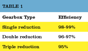
Table 1. The typical overall efficiencies of hydraulic pumps, as shown above, are simply the product of volumetric and mechanical/hydraulic efficiency.Source: Bosch Rexroth
Like theoretical flow, theoretical drive torque can be calculated. For the above pump, in SI units: 100 cc/rev x 207 bar / 20 x p = 329 Newton meters. But like actual flow, actual drive torque must be measured and this requires the use of a dynamometer. Not something we can - or need - to do in the field. For the purposes of this example though, assume the actual drive torque was 360 Nm. Mechanical efficiency would be 91% (329 / 360 x 100 = 91%).
Overall efficiency is simply the product of volumetric and mechanical/hydraulic efficiency. Continuing with the above example, the overall efficiency of the pump is 0.9 x 0.91 x 100 = 82%. Typical overall efficiencies for different types of hydraulic pumps are shown in the Table 1.
System designers use the pump manufacturers’ volumetric efficiency value to calculate the actual flow a pump of a given displacement, operating at a particular pressure, will deliver.
As already mentioned, volumetric efficiency is used in the field to assess the condition of a pump, based on the increase in internal leakage due to wear or damage.
When calculating volumetric efficiency based on actual flow testing, it’s important to be aware that the various leakage paths within the pump are usually constant. This means if pump flow is tested at less than full displacement (or maximum RPM) this will skew the calculated efficiency - unless leakage is treated as a constant and a necessary adjustment made.
For example, consider a variable displacement pump with a maximum flow rate of 100 liters/minute. If it was flow tested at full displacement and the measured flow rate was 90 liters/minute, the calculated volumetric efficiency would be 90 percent (90/100 x 100). But if the same pump was flow tested at the same pressure and oil temperature but at half displacement (50 L/min), the leakage losses would still be 10 liters/minute, and so the calculated volumetric efficiency would be 80 percent (40/50 x 100).
The second calculation is not actually wrong, but it requires qualification: this pump is 80 percent efficient at half displacement. Because the leakage losses of 10 liters/minute are nearly constant, the same pump tested under the same conditions will be 90 percent efficient at 100 percent displacement (100 L/min) - and 0 percent efficient at 10 percent displacement (10 L/min).
To help understand why pump leakage at a given pressure and temperature is virtually constant, think of the various leakage paths as fixed orifices. The rate of flow through an orifice is dependant on the diameter (and shape) of the orifice, the pressure drop across it and fluid viscosity. This means that if these variables remain constant, the rate of internal leakage remains constant, independent of the pump"s displacement or shaft speed.
Overall efficiency is used to calculate the drive power required by a pump at a given flow and pressure. For example, using the overall efficiencies from the table above, let us calculate the required drive power for an external gear pump and a bent axis piston pump at a flow of 90 liters/minute at 207 bar:
As you’d expect, the more efficient pump requires less drive power for the same output flow and pressure. With a little more math, we can quickly calculate the heat load of each pump:
No surprise that a system with gear pumps and motors requires a bigger heat exchanger than an equivalent (all other things equal) system comprising piston pumps and motors.

Gear pumps GP1K Group 1 is an Ideal solution for hydraulic power packs. Modern technologies and many years of experience of the HYDROSILA company allow us to create pumps with high ...
The radial piston pump type R consists of valve-controlled pump elements arranged in star form around an eccentric. For large flow rates, up to 42 pump elements can be ...
PGP 500 pumps offer superior performance, high efficiency and low noise operation at high operating pressures. They are produced in four frame sizes (PGP 502, PGP 505,PGP ...
... Series pump offers variable displacement axial piston pumps for open-circuit applications. Featuring a compact footprint and continuous operating pressure of up to 4,060 psi, PD piston ...

As the new member of the Hydro product range, the hydraulic diaphragm metering pump Hydro/ 2 API 675 (HA2a) meets the requirements of API 675. The pumps stand ...
The key task of external gear pumps is to convert mechanical energy (torque and rotational speed) into hydraulic energy (flow and pressure). To reduce heat loss, Rexroth external gear ...
... and accessibly priced, aluminium gear pumps and motors are among the components most widely utilized in the field of hydraulic applications. Gear pumps ...
Gear pump with reversible Rotation direction and internal drainage. Built in aluminium body, lighter than casting pumps, permits to work at high pressures with a low level of noise.
Gear pumps with heavy duty body, side and rear ports. Double support by taper roller bearings on the agricultural shaft with modified length. Specialty: agriculture long shaft.
Like all the pumps of the HP Series, it is suitable for any hydraulic application which require very high hydraulic output pressures and a moderate and controllable oil flow, to ensure ...
The HP-AP pump, like all HP Series pumps, can be installed in any hydraulic applications which requires high working pressures and moderate and controllable oil flow. Our HP Series air-hydraulic ...
The HP-RC pump, like all the HP Series pumps, can be installed in any hydraulic applications which requires high working pressures and moderate and controllable oil flow. Our HP Series ...
Three piece pumps with aluminum body and flanges, available in single or multiple pump configurations. Stackable with pumps of different families. Wide range of shafts and flanges. Configurations ...
The product range of Bucher Hydraulics includes single pumps 05-100-212-212HP-250HP-300-312HP (corresponding with the common group denominations: 05-1-2-2.5-3) and several combinations of double pumps, ...
... describes Marzocchi external single gear micropumps, ¡heir operating features and hew to select the right pump for the required application. Miaopumps are small hydraulic ...
This electric/hydraulic pump is a two-stage, continuous pressure (demand) pump that contains all the necessary controls and circuitry for powering any single- or double-acting
Gear pumps GP1K Group 1 is an Ideal solution for hydraulic power packs. Modern technologies and many years of experience of the HYDROSILA company allow us to create pumps ...
The pump series Eco-MAX developed by ITH is built for standard applications like service and assembly jobs. The pump series is available in two different designs:
The OMFB offers wide array of gear pumps available for utilization in applications that requires medium, high and very-high pressure of up to 320 bar maximum. These pumps also strictly ...
The pump with a maximum flow rate of 300 bar is specially designed to lessen a volume by means of a fixed crank-driven piston within a cylinder. It has 3 and 4 bolt ISO flange, swash plate and bent axis design piston ...

Hydraulic systems are in general members of the fluid power branch of power transmission. Hydraulic pumps are also members of the hydraulic power pack/hydraulic power unit family. Hydraulic units are encased mechanical systems that use liquids for hydraulics.
The hydraulic systems that hydraulic pumps support exist in a range of industries, among them agriculture, automotive manufacturing, defense contracting, excavation, and industrial manufacturing. Within these industries, machines and applications that rely on hydraulic pumps include airplane flaps, elevators, cranes, automotive lifts, shock absorbers, automotive brakes, garage jacks, off-highway equipment, log splitters, offshore equipment, hydraulic motors/hydraulic pump motors, and a wide range of other hydraulic equipment.
When designing hydraulic pumps, manufacturers have many options from which to choose in terms of material composition. Most commonly, they make the body of the pump–the gears, pistons, and hydraulic cylinders–from a durable metal material. This metal is one that that can hold up against the erosive and potentially corrosive properties of hydraulic fluids, as well as the wear that comes along with continual pumping. Metals like this include, among others, steel, stainless steel, and aluminum.
First, what are operating specifications of their customer? They must make sure that the pump they design matches customer requirements in terms of capabilities. These capabilities include maximum fluid flow, minimum and maximum operating pressure, horsepower, and operating speeds. Also, based on application specifications, some suppliers may choose to include discharge sensors or another means of monitoring the wellbeing of their hydraulic system.
Next, what is the nature of the space in which the pump will work? Based on the answer to this question, manufacturers will design the pump with a specific weight, rod extension capability, diameter, length, and power source.
Manufacturers must also find out what type of substance does the customer plan on running through the pumps. If the application calls for it, manufacturers can recommend operators add other substances to them in order to decrease the corrosive nature of certain hydraulic fluids. Examples of such fluids include esters, butanol, pump oils, glycols, water, or corrosive inhibitors. These substances differ in operating temperature, flash point, and viscosity, so they must be chosen with care.
All hydraulic pumps are composed in the same basic way. First, they have a reservoir, which is the section of the pump that houses stationary fluid. Next, they use hydraulic hoses or tubes to transfer this fluid into the hydraulic cylinder, which is the main body of the hydraulic system. Inside the cylinder, or cylinders, are two hydraulic valves and one or more pistons or gear systems. One valve is located at each end; they are called the intake check/inlet valve and the discharge check/outlet valve, respectively.
Hydraulic pumps operate under the principle of Pascal’s Law, which states the increase in pressure at one point of an enclosed liquid in equilibrium is equally transferred to all other points of said liquid.
To start, the check valve is closed, making it a normally closed (NC) valve. When the check is closed, fluid pressure builds. The piston forces the valves open and closes repeatedly at variable speeds, increasing pressure in the cylinder until it builds up enough to force the fluid through the discharge valve. In this way, the pump delivers sufficient force and energy to the attached equipment or machinery to move the target load.
When the fluid becomes pressurized enough, the piston withdraws long enough to allow the open check valve to create a vacuum that pulls in hydraulic fluid from the reservoir. From the reservoir, the pressurized fluid moves into the cylinder through the inlet. Inside the cylinder, the fluid picks up more force, which it carries over into the hydraulic system, where it is released through the outlet.
Piston pumps create positive displacement and build pressure using pistons. Piston pumps may be further divided into radial piston pumps and axial piston pumps.
Radial pumps are mostly used to power relatively small flows and very high-pressure applications. They use pistons arranged around a floating center shaft or ring, which can be moved by a control lever, causing eccentricity and the potential for both inward and outward movement.
Axial pumps, on the other hand, only allow linear motion. Despite this, they are very popular, being easier and less expensive to produce, as well as more compact in design.
Gear pumps, or hydraulic gear pumps, create pressure not with pistons but with the interlocking of gear teeth. When teeth are meshed together, fluid has to travel around the outside of the gears, where pressure builds.
External gear pumps facilitate flow by enlisting two identical gears that rotate against each other. As liquid flows in, it is trapped by the teeth and forced around them. It sits, stuck in the cavities between the teeth and the casing, until it is so pressurized by the meshing of the gears that it is forced to the outlet port.
Internal gear pumps, on the other hand, use bi-rotational gears. To begin the pressurizing process, gear pumps first pull in liquid via a suction port between the teeth of the exterior gear, called the rotor, and the teeth of the interior gear, called the idler. From here, liquid travels between the teeth, where they are divided within them. The teeth continue to rotate and mesh, both creating locked pockets of liquid and forming a seal between the suction port and the discharge port. Liquid is discharged and power is transported once the pump head is flooded. Internal gears are quite versatile, usable with a wide variety of fluids, not only including fuel oils and solvents, but also thick liquids like chocolate, asphalt, and adhesives.
Various other types of hydraulic pumps include rotary vane pumps, centrifugal pumps, electric hydraulic pumps, hydraulic clutch pumps, hydraulic plunger pumps, hydraulic water pumps, hydraulic ram pumps, portable 12V hydraulic pumps, hydraulic hand pumps, and air hydraulic pumps.
Rotary vane pumps are fairly high efficiency pumps, though they are not considered high pressure pumps. Vane pumps, which are a type of positive-displacement pump, apply constant but adjustable pressure.
Centrifugal pumps use hydrodynamic energy to move fluids. They feature a rotating axis, an impeller, and a casing or diffuser. Most often, operators use them for applications such as petroleum pumping, sewage, petrochemical pumping, and water turbine functioning.
Electric hydraulic pumps are hydraulic pumps powered by an electric motor. Usually, the hydraulic pump and motor work by turning mechanisms like impellers in order to create pressure differentials, which in turn generate fluid movement. Nearly any type of hydraulic pump can be run with electricity. Most often, operators use them with industrial machinery.
Hydraulic clutch pumps help users engage and disengage vehicle clutch systems. They do so by applying the right pressure for coupling or decoupling shafts in the clutch system. Coupled shafts allow drivers to accelerate, while decoupled shafts allow drivers to decelerate or shift gears.
Hydraulic ram pumps are a type of hydraulic pump designed to harness hydropower, or the power of water, to elevate it. Featuring only two moving hydraulic parts, hydraulic ram pumps require only the momentum of water to work. Operators use hydraulic ram pumps to move water in industries like manufacturing, waste management and sewage, engineering, plumbing, and agriculture. While hydraulic ram pumps return only about 10% of the water they receive, they are widely used in developing countries because they do not require fuel or electricity.
Hydraulic water pumps are any hydraulic pumps used to transfer water. Usually, hydraulic water pumps only require a little bit of energy in the beginning, as the movement and weight of water generate a large amount of usable pressure.
Air hydraulic pumps are hydraulic pumps powered by air compressors. In essence, these energy efficient pumps work by converting air pressure into hydraulic pressure.
Hydraulic pumps are useful for many reasons. First, they are simple. Simple machines are always an advantage because they are less likely to break and easier to repair if they do. Second, because fluid is easy to compress and so quick to create pressure force, hydraulic pumps are very efficient. Next, hydraulic pumps are compact, which means they are easy to fit into small and oddly shaped spaces. This is especially true in comparison to mechanical pumps and electrical pumps, which manufacturers cannot design so compactly. Speaking of design, another asset of hydraulic pumps is their customizability. Manufacturers can modify them easily. Likewise, hydraulic pumps are very versatile, not only because they are customizable, but also because they can work in places where other types of pump systems can’t, such as in the ocean. Furthermore, hydraulic pumps can produce far more power than similarly sized electrical pumps. Finally, these very durable hydraulic components are much less likely to explode than some other types of components.
To make sure that your hydraulic pumps stay useful for a long time, you need to treat them with care. Care includes checking them on a regular basis for problems like insufficient fluid pressure, leaks, and wear and tear. You can use diagnostic technology like discharge sensors to help you with detect failures and measure discharge pressure. Checking vibration signals alone is often not enough.
To keep yourself and your workers safe, you need to always take the proper precautions when operating or performing maintenance and repairs on your hydraulic pumps. For example, you should never make direct contact with hydraulic fluid. For one, the fluid made be corrosive and dangerous to your skin. For two, even if the pump isn’t active at that moment, the fluid can still be pressurized and may potentially harm you if something goes wrong. For more tips on hydraulic pump care and operation, talk to both your supplier and OSHA (Occupational Safety and Health Administration).
Pumps that meet operating standards are the foundation of safe and effective operations, no matter the application. Find out what operating standards your hydraulic pumps should meet by talking to your industry leaders.
The highest quality hydraulic pumps come from the highest quality hydraulic pump manufacturers. Finding the highest quality hydraulic pump manufacturers can be hard, which is why we have we listed out some of our favorites on this page. All of those whom we have listed come highly recommended with years of experience. Find their information nestled in between these information paragraphs.
Once you have put together you list, get to browsing. Pick out three or four hydraulic pump supply companies to which you’d like to speak, then reach out to each of them. After you’ve spoken with representatives from each company, decide which one will best serve you, and get started on your project.

Hydraulics are essential in many industrial applications; they use mechanical energy to force liquid into a system. Within the category of hydraulics, there are many different types of hydraulic pumps that accomplish various tasks within industrial fields. Let’s take a look at some of them.
An axial piston hydraulic pump is also a positive displacement pump. Axion pumps have cylinders that are assembled around a central axis (cylinder block). Within each cylinder, there are pistons which will attach to a swashplate or wobble plate. These swashplates then connect to the rotating shaft, which moves the pistons and pulls them in and out of the cylinders.
Axial piston pumps can also be made into variable displacement piston pumps, which provide more control over speed. In variable pumps, the swashplate is used to set the depth of the pistons, which creates a length variation to affect the discharge volume. This design helps maintain constant discharge rates in industrial applications.
Another hydraulic pump type is the radial piston pump. As the name suggests, the pistons are arranged along the radius of the cylindrical block, which includes the pintle and rotor. The rotor powers the pistons through the cylinders and forces hydraulic fluid in and out of the cylinder.
Both axial and radial piston pumps are used for high-operating pressures as they can withstand much higher pressures than hydraulic pump types. They are often used in ice and snow control applications, as well as on truck-mounted cranes.
A rotary vane pump is also a type of positive displacement pump. It uses rigid vanes rather than the rotor hubs. These vanes are placed around an eccentric rotor device, which moves around the inside wall of the housing container. This movement forces the hydraulic fluid through the discharge port, and, in some applications, can be adjusted to align with the rotational axis of the motor.
Vane pumps are often used in utility vehicles but have lost popularity over the years in favor of gear pump hydraulic systems. However, they used to be very common in aerial buckets and ladders along with other mobile, truck-mounted hydraulic applications.
Gear pumps have become the most common hydraulic pump type that’s used in industrial applications today. The gear pump has fewer moving parts than piston or vane pumps, which makes it easy to service and relatively inexpensive compared to other hydraulic pumps. They are also less likely to be contaminated during use.
An external gear pump uses two gears on the outside of individual shafts to aid in movement and push both thin and thick fluids through the gears. These external pumps are commonly used in fixed-displacement applications and high-pressure environments.
Internal gear pumps place gears on the insides of the shafts rather than on the outside as found in external gear pumps. That makes them self-priming and non-pulsing, and can even be run without liquid for short periods of time—although they can’t be left dry for too long.
Additionally, internal gear pumps are bi-rotational, meaning that one can be utilized to both unload and load devices. And, with only two moving parts, they are considered to be one of the most reliable types of hydraulic pumps.
Volumetric efficiency is the amount of output the pump actually produces as a percentage of its theoretical production.The higher the percentage the more efficient the pump.
Among the factors affecting volumetric efficiency are leakage and fluid compressibility (ability for volume to be reduced under pressure). These issues can cause the pump to lose efficiency and waste energy as that energy converts to heat.
Still have questions about hydraulic pumps or their parts and repairs? Contact Panagon Systems today. We’ve been a leading hydraulic pump manufacturer in the U.S. for over two decades, and can help you find the best solution for your application. You can view our full line of pumps here. To request a consultation or quote, please fill out our online form.

Volumetric efficiency is the actual amount of fluid flowing through a pump, rather than its theoretical maximum. Put another way, it is the measure of volumetric losses of a reciprocal pump through internal leakage and fluid compression; this calculation is the value that should be used to evaluate your current pumping mechanism.
Common causes of loss in volumetric efficiency include worn valves, seats, liners, piston rings, or plungers, pockets of air or vapor in the inlet line or trapped above the inlet manifold, or loose belts, valve covers, cylinder heads, or bolts in the pump inlet manifold. Routine maintenance and inspection in these areas can greatly increase output over time.
Obstructions such as a safety relief valve partially held open or failing to maintain pressure, foreign objects preventing the pump inlet or discharge valve from closing or blocking liquid passage, or a vortex in the supply tank are some of the other more easily remedied factors reducing efficiency.
There are many potential hazards that can hamper volumetric efficiency and cause your components to operate at less than full strength — but there are also a number of methods to increase it.

?I just love this newsletter. As a Hydraulics Instructor for Eaton, I make copies and distribute them to my students as I address various topics. Please keep "em coming.?

Although many detractors sneer at the idea of hydraulic efficiency, right-sizingcomponents, proper system design and moderntechnology can go a long way to achieving system efficiency.
“Hydraulic efficiency”is a term alluding similar sentiments to “exact estimate” or “scientific belief.” It’s not that hydraulic efficiency is an oxymoron, per se, but these aren’t traditionally two words that make sense shoulder to shoulder. If efficiency was your top benefit on the list of machine requirements, fluid power wouldn’t have been on your short list of options, at least in the past half-century or longer.
Efficiency is a word now more commonly familiar to us, thanks to the escalation of green values—especially those defining the way we use natural resources. No longer can we take a limitless and inexpensive source of energy for granted, nor can we abuse the dirty sources of inexpensive energy at the expense of our precious environment. We must take full advantage of our energy resources to achieve the work required for maintaining our standard of living, while reducing associated waste along the way.
What is efficiency?I define efficiency as work-in minus work-out. Essentially, it’s the differential between the energy your process requires and the energy input required to achieve that process. Your process could be stamping, rolling, injecting, moving, pressing or any other mechanical function capable of being achieved in a rotational or linear motion. If you’re running a punch press, for example, the machine efficiency is defined as the current draw of the pump’s motor minus the combined force and velocity of the punch die.
Most machines are designed to convert energy from one form to another, which can sometimes occur multiple times. Because of the Laws of Thermodynamics, you cannot change energy from one form to another without creating waste energy, and this is a fact regardless of the energy transformation taking place. In the case of a hydraulic machine, you must convert electrical energy to mechanical energy within the electric motor, resulting in partial waste. Then you must convert mechanical energy into hydraulic energy within the pump, resulting in partial waste. Then you must convert hydraulic energy back into mechanical energy at your cylinder or hydraulic motor, resulting in partial waste.
The amount of energy wasted in the above example could be staggering, especially if you’re using an old machine with old components. Let’s say you have a 10-hp electric motor—and keep in mind electric motors are rated on power consumption, not power output. Your old motor might have an efficiency of 85%, meaning it will produce 8.5 hp at its shaft, the other 1.5 hp being wasted as pure heat.
In your old power unit, you have a worn and tired gear pump. When new, a gear pump is lucky to have 80% efficiency, so I’ll be generous to throw 75% at this example, since gear pumps become less efficient over their lifetimes. So this pump can convert only 6.4 of the motor’s 8.5-hp shaft output into usable hydraulic energy. The rest of the energy is, you guessed it, wasted as pure heat. We’ve now lost 36% of the electrical energy inputted, and we haven’t even done anything yet.
Just to be intentionally derisive, I’m going to choose a hydraulic motor as our actuator; a gerotor motor to be exact. These motors come at a modest price and perform at a modest level. They were a clever design back in the day, but have high leakage to lubricate the myriad components, and they leak even more if you operate them outside their optimum torque and speed curve. Leakage, I should note, is a designed element of most hydraulic components, based on gaps and clearances with internal moving parts, which is required to lubricate that component. More moving parts or higher clearances means more leakage, and I should further note, any fluid lost to leakage carries with it pure heat equal to the pressure and flow of the leakage.
Now that I’ve blasted gerotor motors, I’ll back it up by saying they’re often incapable of reaching 80% efficiency. There are some versions of these “orbital” motors, like the disc valve variant, which can be close to 90% efficient, but it would be only within a tiny window of flow and pressure. I’ll stick with 80% for this example, which is generous. With the 6.4 hydraulic horsepower we havein our system, we’re left with 5.1 hp at the hydraulicmotor’s shaft.
So with barely half of our input energy making its way to the output stage, it’s easy to see why I’m dubious of “hydraulic efficiency.” So why use hydraulics when we could have powered our machine straight from the electric motor and take advantage of 8.5 hp instead of 5.1? In that answer lies the reason hydraulics are awesome; with $300 worth of valving, you can infinitely vary torque and speed, and reverse direction. Our electric motor would require sophisticated electronic control to achieve the same features.
To be fair, I’m using one of the worst-case examples for hydraulic efficiency. Not only are there more efficient components available than gear pumps and orbital motors, there are ingenious approaches to using hydraulic components. Furthermore, recent advances in electronic control have not ignored the fluid power industry, and there are some tricks to further improve hydraulic efficiency.
Pressure compensated pumps are set to a particular standby pressure, and when this pressure is reached, the pump reduces flow until downstream pressure drops below that standby pressure. Image courtesy of CD Industrial Group
I can’t stress enough that a hydraulic machine is really just an energy conversion device, and when you can convert your input energy into usable force with as little heat waste as possible, you’re on the right track. A pump converts the mechanical energy of the prime mover into hydraulic energy in the form of pressure and flow. If I were to recommend one component you blow the bankroll on, it would be the pump.
A piston pump, especially a high-quality one, can be 95% efficient at converting input energy into hydraulic energy. Not only does this pump provide 27% more available hydraulic energy than our old gear pump, it creates 80% less waste heat than it, reducing or eliminating cooling requirements.
Not only does an efficient pump help, an efficient design works wonders. If you have a fixed displacement pump on a flow control, any unused fluid is wasted as heat. For example, take even our 95% efficient fixed piston pump, giving us 9.5 gpm out of a theoretical 10 gpm. If your downstream priority flow control valve is set to 5 gpm, 4.5 gpm is bypassed to tank. However, all of the 9.5 gpm is still being created at full system pressure, and what’s dumped to tank is lost as heat. So now our 95% efficient pump is helping create a 50% inefficient system.
A load-sensing pump will provide only the pressure and flow required of the circuit and actuator, with only a few hundred psi worth of pressure drop as the waste by-product. Image courtesy of CD Industrial Group
To get around this, pressure compensation was created. A pressure compensated pump is set to a particular standby pressure, and when this pressure is reached, the pump reduces flow until downstream pressure drops below that standby pressure. For example, if you have a 10 gpm pump set at 3,000 psi, and flow is restricted below 10 gpm, the pump will reduce its displacement to exactly match the downstream flow and pressure drop at 3,000 psi. Essentially, the pump only produces the flowbeing asked for, no more, but always at 3,000 psi.
But what if we only want 1,000 psi for a particular operation? Well, you could use a pressure-reducing valve, but the pump is still producing 3,000 psi, so you’re not saving any energy. To remedy this, the load-sensing pump was invented. A load sensing pump has an additional compensator that is plumbed downstream of the metering valve. This configuration allows it to measure load pressure and compare it to compensator pressure. The result is the pump will provide only the pressure and flow required of the circuit and actuator, with only a few hundred psi worth of pressure drop as the waste by-product.
The use of variable speed technology can dramatically increase hydraulic efficiency. Here, the new Green Hydraulic Power units use Siemen’s SINAMICS variable speed servo pump drive to increase efficiency by up to 70%.
Recent advancements in control technology have resulted in a similar concept of pressure and flow management, but using a combination of fixed displacement pumps, servo or VFD motors and pressure transducers. The pressure transducers measure pressure after the pump and after the metering valves, and PLC gives the signal to rotate the pump at a speed only fast enough to achieve the desired pressure and flow. It’s quite an advanced technology, and has progressed to the point a pump could hold a stationary load and rotate fractional speed just to compensate for leakage. Another advantage to this technology is that the motor doesn’t even turn when no energy is required, and then again only with the energy required by demand of the hydraulic system.
Aside from choosing efficient pump designs, using efficient hydraulic actuators is the next best place to continue. Not much can be said of hydraulic cylinders, because most are close to 100% efficient already, depending on sealing technology. But just like with your hydraulic pump, the hydraulic motor has many variations, each with their own contribution to overall efficiency.
So for the most part, hydraulics is not an efficient technology. But neither are gasoline-powered cars, and millions of those are sold every day, because there is no better option for their task. Regardless, efficiency in hydraulics is progressing, and advancements in materials and technologies will further that. As long as you are aware of what it takes to create “hydraulic efficiency,” the term won’t seem curious like “seriously funny” or “virtual reality.”

A hydraulic pump is a mechanical device that converts mechanical power into hydraulic energy. It generates flow with enough power to overcome pressure induced by the load.
A hydraulic pump performs two functions when it operates. Firstly, its mechanical action creates a vacuum at the pump inlet, subsequently allowing atmospheric pressure to force liquid from the reservoir and then pumping it through to the inlet line of the pump. Secondly, its mechanical action delivers this liquid to the pump outlet and forces it into the hydraulic system.
The three most common hydraulic pump designs are: vane pump, gear pump and radial piston pump. All are well suited to common hydraulic uses, however the piston design is recommended for higher pressures.
Most pumps used in hydraulic systems are positive-displacement pumps. This means that they displace (deliver) the same amount of liquid for each rotating cycle of the pumping element. The delivery per cycle remains almost constant, regardless of changes in pressure.
Positive-displacement pumps are grouped into fixed or variable displacement. A fixed displacement pump’s output remains constant during each pumping cycle and at a given pump speed. Altering the geometry of the displacement chamber changes the variable displacement pump’s output.
Fixed displacement pumps (or screw pumps) make little noise, so they are perfect for use in for example theatres and opera houses. Variable displacement pumps, on the other hand, are particularly well suited in circuits using hydraulic motors and where variable speeds or the ability to reverse is needed.
Applications commonly using a piston pump include: marine auxiliary power, machine tools, mobile and construction equipment, metal forming and oil field equipment.
As the name suggests, a piston pump operates through pistons that move back and forth in the cylinders connected to the hydraulic pump. A piston pump also has excellent sealing capabilities.
A hydraulic piston pump can operate at large volumetric levels thanks to low oil leakage. Some plungers require valves at the suction and pressure ports, whilst others require them with the input and output channels. Valves (and their sealing properties) at the end of the piston pumps will further enhance the performance at higher pressures.
The axial piston pump is possibly the most widely used variable displacement pump. It’s used in everything from heavy industrial to mobile applications. Different compensation techniques will continuously alter the pump’s fluid discharge per revolution. And moreover, also alter the system pressure based on load requirements, maximum pressure cut-off settings and ratio control. This implies significant power savings.
Two principles characterise the axial piston pump. Firstly the swash plate or bent axis design and secondly the system parameters. System parameters include the decision on whether or not the pump is used in an open or closed circuit.
The return line in a closed loop circuit is under constant pressure. This must be considered when designing an axial piston pump that is used in a closed loop circuit. It is also very important that a variable displacement volume pump is installed and operates alongside the axial piston pump in the systems. Axial piston pumps can interchange between a pump and a motor in some fixed displacement configurations.
The swivel angle determines the displacement volume of the bent axis pump. The pistons in the cylinder bore moves when the shaft rotates. The swash plate, in the swash plate design, sustain the turning pistons. Moreover, the angle of the swash plate decides the piston stroke.
In general, the largest displacements are approximately one litre per revolution. However if necessary, a two-litre swept volume pump can be built. Often variable-displacement pumps are used, so that the oil flow can be adjusted carefully. These pumps generally operate with a working pressure of up to 350–420 bars in continuous work
Radial piston pumps are used especially for high pressure and relatively small flows. Pressures of up to 650 bar are normal. The plungers are connected to a floating ring. A control lever moves the floating ring horizontally by a control lever and thus causes an eccentricity in the centre of rotation of the plungers. The amount of eccentricity is controlled to vary the discharge. Moreover, shifting the eccentricity to the opposite side seamlessly reverses the suction and discharge.
Radial piston pumps are the only pumps that work continuously under high pressure for long periods of time. Examples of applications include: presses, machines for processing plastic and machine tools.
A vane pump uses the back and forth movement of rectangle-shaped vanes inside slots to move fluids. They are sometimes also referred to as sliding vane pumps.
The simplest vane pump consists of a circular rotor, rotating inside of a larger circular cavity. The centres of the two circles are offset, causing eccentricity. Vanes slide into and out of the rotor and seal on all edges. This creates vane chambers that do the pumping work.
A vacuum is generated when the vanes travel further than the suction port of the pump. This is how the oil is drawn into the pumping chamber. The oil travels through the ports and is then forced out of the discharge port of the pump. Direction of the oil flow may alter, dependent on the rotation of the pump. This is the case for many rotary pumps.
Vane pumps operate most efficiently with low viscosity oils, such as water and petrol. Higher viscosity fluids on the other hand, may cause issues for the vane’s rotation, preventing them from moving easily in the slots.
Gear pumps are one of the most common types of pumps for hydraulic fluid power applications. Here at Hydraulics Online, we offer a wide range of high-powered hydraulic gear pumps suitable for industrial, commercial and domestic use. We provide a reliable pump model, whatever the specifications of your hydraulic system. And we furthermore ensure that it operates as efficiently as possible.
Johannes Kepler invented the gear pump around year 1600. Fluid carried between the teeth of two meshing gears produces the flow. The pump housing and side plates, also called wear or pressure plates, enclose the chambers, which are formed between adjacent gear teeth. The pump suction creates a partial vacuum. Thereafter fluid flows in to fill the space and is carried around the discharge of the gears. Next the fluid is forced out as the teeth mesh (at the discharge end).
Some gear pumps are quite noisy. However, modern designs incorporating split gears, helical gear teeth and higher precision/quality tooth profiles are much quieter. On top of this, they can mesh and un-mesh more smoothly. Subsequently this reduces pressure ripples and related detrimental problems.
Catastrophic breakdowns are easier to prevent with hydraulic gear pumps. This is because the gears gradually wear down the housing and/or main bushings. Therefore reducing the volumetric efficiency of the pump gradually until it is all but useless. This often happens long before wear causes the unit to seize or break down.
Can hydraulic gear pumps be reversed? Yes, most pumps can be reversed by taking the pump apart and flipping the center section. This is why most gear pumps are symmetrical.
External gear pumps use two external spur gears. Internal gear pumps use an external and an internal spur gear. Moreover, the spur gear teeth face inwards for internal gear pumps. Gear pumps are positive displacement (or fixed displacement). In other words, they pump a constant amount of fluid for each revolution. Some gear pumps are interchangeable and function both as a motor and a pump.
The petrochemical industry uses gear pumps to move: diesel oil, pitch, lube oil, crude oil and other fluids. The chemical industry also uses them for materials such as: plastics, acids, sodium silicate, mixed chemicals and other media. Finally, these pumps are also used to transport: ink, paint, resins and adhesives and in the food industry.
Mathematical calculations are key to any type of hydraulic motor or pump design, but are especially interesting in the gerotor design. The inner rotor has N teeth, where N > 2. The outer rotor must have N + 1 teeth (= one more tooth than the inner rotor) in order for the design to work.

In this article we"ll dive into hydraulic motor calculations and the important topic of efficiency. Many hydraulic calculators ignore efficiency altogether and merely calculate theoretical values with 100% efficiency. Manufacturers typically don"t get too deep into efficiency either.
Volumetric efficiency accounts for the leakage of fluid through the motor that doesn"t do any work. Mechanical/hydraulic efficiency accounts for friction losses. Total efficiency is volumetric efficiency X mechanical/hydraulic efficiency.
Depending on what you"re calculating, one of these efficiencies will be important. For flow rate and speed, volumetric efficiency is important. For displacement, pressure drop, and torque, mechanical efficiency is important. Finally, for output power, total efficiency is important.
A hydraulic motor has two input variables: pressure and flow. We"ll look at the cases of constant pressure drop and constant flow rate to illustrate the efficiencies.
Consider the motor data below for a constant pressure drop. The theoretical values for pressure drop, speed and torque where calculated using the hydraulic motor equations using 100% efficiencies.
If we plot the flow rate vs. speed for the actual and theoretical data, there is an offset. In other words, for a given flow rate, the actual speed is less than the theoretical speed. This difference is due to volumetric efficiency.
If we plot the pressure drop vs. output torque for the actual and theoretical data, there is an offset. In other words, for a given pressure drop, the actual torque is less than the theoretical torque. This difference is due to mechanical/hydraulic efficiency.
If we enter the chart at 17.5 GPM on the x-axis and go to the midpoint between the curves, we can get mechanical/hydraulic efficiency on the y-axis. In this case, efficiency is 87%.
External gear pumps and motors are robust and low cost positive displacement machines and are widely used in industrial and mobile applications. Nowadays however, optimal global efficiency represents a more crucial aspect to be considered when designing a hydraulic machine. For this reason, it becomes a primary necessity to investigate the phenomena which determine and affect the hydraulic machine total efficiency. In this work, the volumetric efficiency dependence on the operating speed and delivery pressure of external gear pumps is investigated by means of a mathematical model already presented in a previous paper and the results obtained are compared with experimental data.
First of all, the mathematical model is briefly presented; then the predicted results are discussed considering the influence of the pump operating conditions. Moreover, the influence on the volumetric efficiency of the behaviour of the hydraulically balanced bearing blocks, which are responsible of the pump axial balance, is exposed. In particular, it is shown that the tilted position of the bearing blocks and the height of the lateral clearances can greatly affect the volumetric efficiency.
The data coming from an experimental investigation carried out on commercial external gear pump units are then presented; both the volumetric and the mechanical efficiency have been measured.
The comparison between the experimental data and the numerical results allows discussing the bearing blocks balancing behaviour during pump operation.
Your final drive includes a hydraulic motor and that motor has a certain level of efficiency associated with it. Over time, that efficiency can drop -- so find out how efficiency is measured, what the source of losses are, and how to minimize them.
No system, no matter how well it’s designed, is going to be 100% efficient. High-quality, well-maintained radial piston motors are about 95% efficient while axial piston motors are about 90% efficient--which is likely why you see these two types of hydraulic motors used in the vast majority of final drive motors.
The definition of efficiency depends on what type of system you’re talking about, and even then there can be some variations. For a hydraulic motor, there are three ways efficiency can be measured or estimated: volumetric, mechanical/hydraulic, and overall efficiency.
Volumetric efficiency looks at the theoretical flow rate and the actual flow rate and provides information about leakage and wear. The theoretical flow rate is pretty easy to calculate: theoretical flow = (pump displacement per revolution) x (revolution speed).
This works much better in SI units, too. If the displacement is in cc/rev and the speed is in rpm, the results will be in liters/minute. Actual flow is then measured using a flow meter. The efficiency is then actual flow / theoretical flow x 100 to get efficiency as a percent.
Mechanical efficiency is based on actual work done and theoretical work done, both per revolution. This is based on theoretical torque and the actual torque, and in most hydraulic motors it’s about 0.9 (or 90%). Actual torque can be measured with a dynamometer, but is rarely done. The losses related to mechanical efficiency are directly tied to mechanical friction between mating parts.
Overall efficiency combines volumetric and mechanical efficiency. It"s simply the product of these two values: overall efficiency = mechanical efficiency x volumetric efficiency, and gives you an overall idea of how efficient your hydraulic motor is.
Some degree of internal leakage is normal and actually beneficial, but past a certain point it becomes a problem. Excess internal leakage most often results from wear. For example, the size of key clearances in a hydraulic motor can, over time, become larger because of abrasive wear and lead to internal leakage. That type of wear usually results from contaminated hydraulic fluid but can also result from normal wear and tear.
Friction is another major source of losses. Rough surfaces where they should be smooth cause friction issues with the hydraulic fluid, reducing the amount of power that can be transferred. There are other ways that friction can be introduced, however. For example, anti-friction bearings or plane bearings that are wearing out will be a source of friction.
One of the keys to preventing hydraulic motor losses relates to good maintenance practices, such as keeping the hydraulic fluid clean, replacing hydraulic filters, and not ignoring hydraulic leaks. It"s also important to look for symptoms of potential problems with the bearings, such as new noises, excessive vibration, and overheating.


 8613371530291