
wagner hydraulic pump quotation

Receive unparalleled services and products from Wagner Hydraulic Equipment Co. Our business is dedicated to becoming one of the top companies in the industry. We work hard to make sure that we always satisfy your needs.
We are committed to deliver excellence in everything we do. Our staff knows that the only way we can become a successful business is by making you happy. Feel confident that you are receiving exceptional products and services by choosing Wagner Hydraulic Equipment Co.

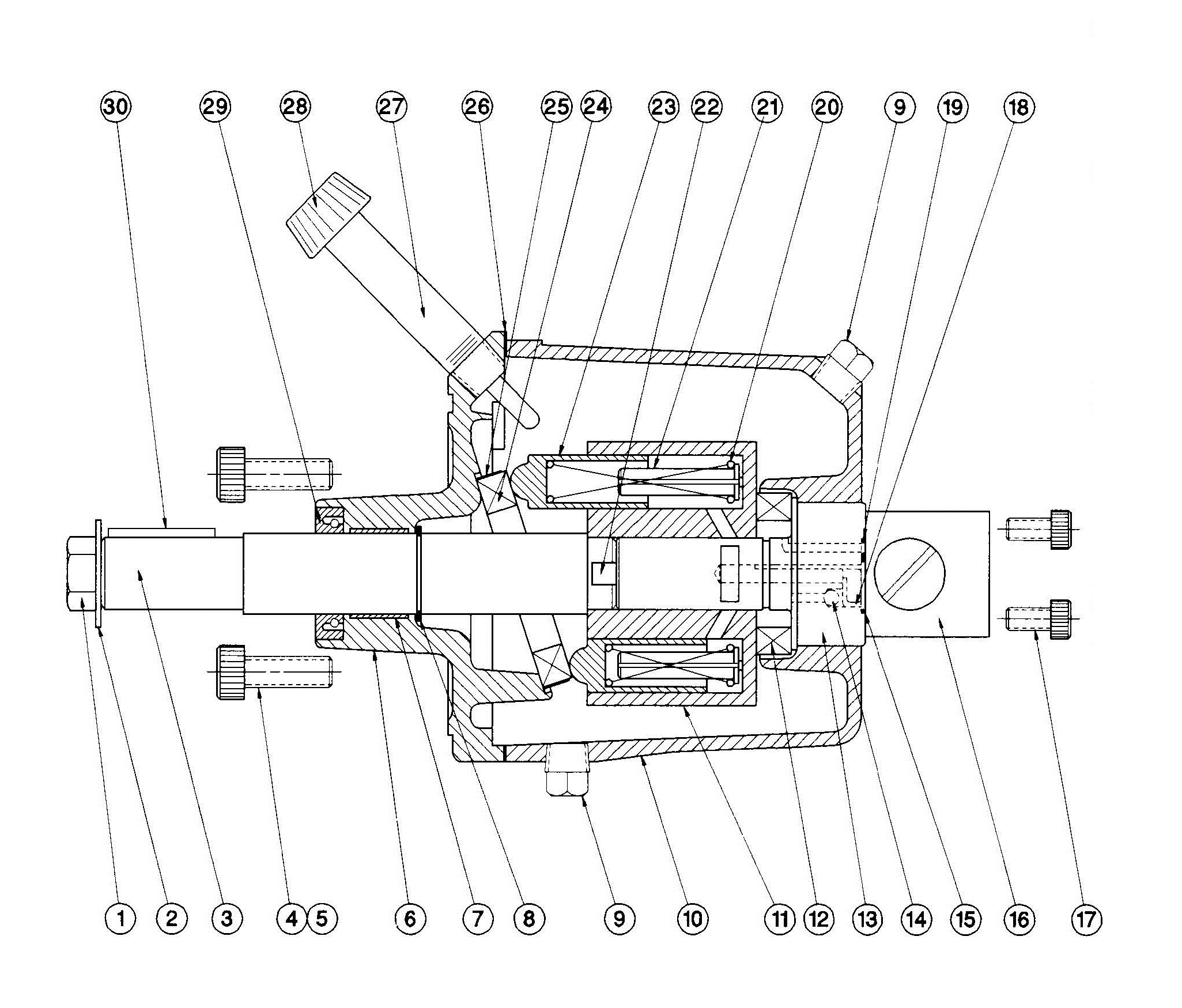
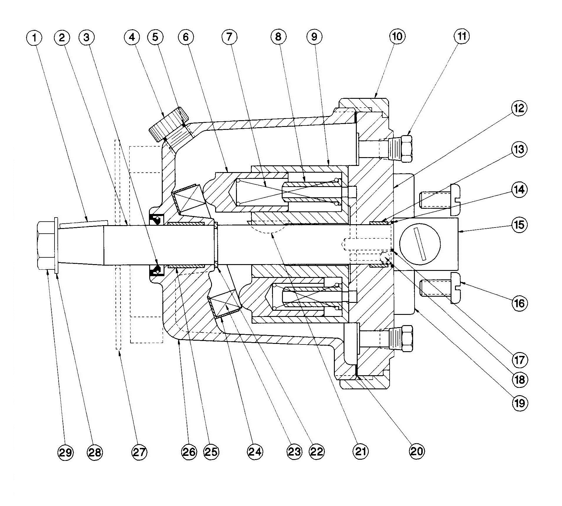
Titan 0005311 Piston Spring / Pressure spring for Diaphragm pump Fits: ED655 Plus Airless Pump, ProFinish AS1130 and AirCoat Air-Assisted Airless spray gun

Viking Pump is a Unit of IDEX Corporation and an international leader in Rotary Positive Displacement Pump design and fabrication. Their pumps can be used to pump a wide variety of liquids ranging from hot and water-thin to cold and viscous. As a stocking distributor of Viking Pump, we have many sizes of pumps in stock at our facilities, ready to go.
Cummins-Wagner has worked with Viking since 1969, and Siewert Equipment (NY Division) has worked with Viking since 1957, to best serve our customers in the commercial and industrial markets.
Cummins-Wagner has been a leading expert in pumps since 1960. Our application engineers will be able to recommend the best-fit pump products for your application.Cummins-Wagner also offers 24/7 service and repair on all products we carry and more.
Viking Pump products have the major benefit of coming from facilities that handle everything from cast to finished product, which enables them to deliver customized pump solutions to your exact specifications in a timely, cost-effective manner. Some other benefits of Viking Pump include:
Grommit, wasn"t aware the AW"s were a lot different than the AX models, I think both are 1.95 cube models, but must be different mounting scenario, I have never seen one so no basis for knowledge, good luck with search, there is a guy named Wayne at Marine-Plus.com, he"s an old Wagner guru, he might know, web site has his email. Also Baltimore Hydraulics will rebuild old Wagner helms, they might be of some assistance.
The specification of the patent in suit states that it relates to "hanger bracket pump mountings for tractors equipped with loader frames." The specification refers to apparatus in which "the hydraulic pump which powers the boom and other tractor attachments is mounted on the base or loader frame of the tractor" and further states:
"* * * This pump receives power from the engine drive shaft through an extension shaft having a flexible coupling to accommodate for movment of the frame respecting the tractor when the frame is stressed under load or otherwise. In actual practice the coupling is frequently damaged by excessive frame movement, and it has been a source of equipment breakdown.
"It is the object of the present invention to re-locate the pump and to mount it directly from the tractor and, specifically, upon the hanger plate to which the underslung U-shaped member of the loader frame is connected. The re-located pump, accordingly, receives direct support from the tractor and is not subject to stresses imposed upon the loader.
"The invention consists in mounting the loader system pump in fixed relation to the tractor and in alignment with the tractor drive shaft and upon a platform specially provided on the hanger plate aforesaid. In one embodiment of the invention the U-shaped member of the loader frame is rigidly connected to the bracket to transmit bending stresses in the loader frame directly to the tractor. In another embodiment of the invention the U-shaped member of the loader frame is pivotally connected to the hanger bracket to relieve the tractor from such bending stresses."
"1. A hanger plate for attachment to a tractor having a loader frame subject to bending stress and a forwardly projecting drive shaft, said plate being provided with means for releasably mounting it on the tractor, a platform forwardly extending from said plate and mounting means on the platform to which a pump may be secured through said platform and hanger plate directly to said tractor and in alignment with said tractor drive shaft, said hanger plate further comprising means for mounting said loader frame on the tractor independent of said pump mounting means whereby bending stresses imposed on the loader frame are transmitted directly to the tractor without affecting the pump and its alignment with the tractor drive shaft.
"12. In combination, a tractor having a forwardly projecting power take-off shaft, a loader frame and a hydraulic system requiring a pump for its operation, means supporting the loader frame detachably on the tractor and including a bracket in rigid connection with the front of the tractor and having a releasable connection with the loader frame, certain portions of the frame being yieldable for relative movement respecting the bracket, a pump for said hydraulic system provided with a rigid mounting to said bracket independently of yieldable portions of the frame and having a drive shaft coupled with the tractor power take-off shaft, and hydraulic connections carried by the frame and having inlet and outlet connection with the pump and flexible to accommodate such yielding without affecting the pump or coupling.
"21. In a device of the character described, a combined tractor loader frame hanger and mounting for a pump, comprising a plate, means for connecting the plate to the tractor, a platform projecting forwardly from said plate and comprising means upon which said pump may be mounted, said plate being further provided with depending means for the connection thereto of said loader frame."
In the commercial device of the patent in suit, the plate is rigidly attached to the front portion of the frame of the tractor. A bracket which embraces a platform is welded to the plate. The pump is mounted on the platform, with its drive shaft in alignment with the drive shaft of the tractor motor. The drive shaft of the tractor motor is extended and is releasably connected with the drive shaft of the pump. An underslung U-shaped portion of the loader frame, which extends beneath the tractor body, embraces a bracket welded to such U-shaped portion and such bracket is bolted to the plate by three bolts. The holes in the bracket and plate through which the three bolts extend are larger than the bolts, so as to permit a limited movement of the loader frame relative to the plate. Clearly, the bolt mounting is not a pivotal mounting nor the equivalent of a pivotal mounting.
Each of the alleged infringing devices mounts the pump on a bracket rigidly attached by bolts to the front portion of the tractor frame and each employs an extended drive shaft of the motor connected to and in alignment with the drive shaft of the pump. In the Shawnee device the transverse section of the U-shaped member is slidably mounted in a channel. The channel is composed of three plates welded together at right angles, leaving the front side open. The channel is mounted on a bracket which is attached to the front end of the motor frame and which bracket also carries the pump.
In the alleged infringing device of Henry, a plate is rigidly mounted on the front portion of the tractor frame, to which is attached the bracket which carries the pump. The transverse section of the U-shaped portion of the loader frame is attached to the plate by two pivots, one near each end of such transverse section. The pivots are formed by a sleeve attached to the bracket and a round, pinlike member with a head which extends through the transverse section into the sleeve. It will thus be seen that both infringing devices have means by which the U-shaped portion of the frame may move relative to the member to which it is attached.
4. A pump for the hydraulic system, provided with a rigid mounting to said bracket independently of yieldable portions of the loader frame and having a drive shaft coupled with the tractor power take off shaft;
5. Hydraulic connections carried by the loader frame and having inlet and outlet connections with the pump and flexible to accommodate such yielding without affecting the pump or coupling.
The narrow question then presented is whether the concept which embraces the plate rigidly attached to the front portion of the tractor frame, the bracket attached to such plate, the platform on the bracket, the hydraulic pump mounted on such platform, with its shaft in alignment with and connected to the extended shaft of the motor, and the mounting of the U-shaped portion of the loader frame on the bracket or plate, arose to the dignity of invention.
The proof established that the invention covered by the patent was conceived by Werner and Wagner, Iron Works" assignors, shortly before May 15, 1951. Prior to that date, Iron Works was manufacturing the Simmonds loader frame for Dearborn Motors Corporation, the owner of Simmonds Patent No. 2,495,144, issued January 17, 1950, and was also manufacturing loader frames for other customers. Iron Works mounted the hydraulic pump on the front end of the loader frame. Stresses generated by the loader frame caused excessive breakage of the pump drive shaft, with resultant injury to other portions of the equipment. Werner and Wagner, executives of Iron Works, undertook to design a loader frame and pump that would solve the problem. The experimental work was done by employees of Iron Works under the direction of Werner and Wagner and resulted in a device substantially like the commercial device of the patent in suit, described above. The new loader frame and pump were placed on the market prior to May 15, 1951, and the first work was done on the manufacture of the commercial device about May 15, 1951. The experimental device manufactured under the direction of Werner and Wagner and the commercial devices employed 5/8 inch bolts and 11/16 inch holes to mount the transverse section of the U-shaped member of the loader frame on the plate.
The concept of mounting the hydraulic pump on a bracket rigidly attached to the front portion of the frame of the tractor, with the pump drive shaft in alignment with and connected to an extension of the drive shaft of the tractor was not new, when in 1951 Werner and Wagner conceived the device of the patent in suit. It was disclosed by Machin in his Patent No. 2,479,048, applied for October 16, 1946, and granted August 16, 1949, assigned to Ottawa Steel Products, Inc. In his specifications Machin stated, "I provide a pump supported on the tractor frame by brackets by bolts or the like. A shaft extends through a bushing secured to the bracket members by bolts or the like and engages within a connecting collar on the end of the extension shaft having a universal joint connection with the crank shaft of the tractor * * *."
In Drawing No. 5 of his patent, Machin illustrates a pump mounted on a bracket, which bracket is rigidly attached to the frame of the tractor and an extended drive shaft of the pump in alignment with the crank shaft of the tractor and the two shafts connected by a universal joint.
Moreover, in 1946 Ottawa Steel Products was engaged in the manufacture of front end loaders for farm tractors in which the hydraulic pump was mounted on the loader frame and experienced shaft breakage resulting from shaft misalignment caused by stresses generated by movements of the loader frame.
To meet that problem the engineers of Ottawa Steel Products in 1947, following the teaching of Machin, mounted the pump on the front portion of the tractor frame by means of a "pump plate strut support assembly," rigidly mounted the loader frame on the plate support assembly, positioned the pump so its drive shaft was in line with the drive shaft of the motor and connected the two drive shafts by a flexible coupling. They thus solved as early as 1947 the problem of pump drive shaft breakage and resulting damage caused by misalignment of the pump drive shaft.
Thus it will be seen that the only novelty in the device conceived and built by Werner and Wagner was the mounting of the loader frame on the plate by means of bolts that were smaller in diameter than the holes through which they extended, thus permitting the limited movement by the loader frame relative to the plate — a mounting not described nor validly claimed in the patent. Moreover, we are of the opinion that it would be obvious to an ordinary mechanic, skilled in the art, that the problem of pump crank shaft breakage resulting from mounting the pump on the loader frame and the transmission of loader frame stresses to the pump crank shaft would be solved by rigidly mounting the pump on the front portion of the tractor frame, mounting the transverse section of the U-shaped member of the frame on such tractor frame and aligning the pump drive shaft and the tractor drive shaft and connecting them together, so that stresses which would cause the motor drive shaft to move would cause the same movement of the pump drive shaft and thus keep the two drive shafts in fixed relation, whereby misalignment of the shafts would be avoided.
"This application is a continuation-in-part of our co-pending application, Serial No. 357,284 filed May 25, 1953, now abandoned, and entitled `Pump Mounting.""
We do not pass on the question not raised by counsel, but which lurks in the record, as to whether Werner and Wagner were not entitled to the patent, because the device of the patent in suit was "in public use or on sale in this country, more than one year prior to the date of the application for patent. * * *" See 35 U.S.C., 1946 Ed., § 31 and 35 U.S.C.A. § 102.

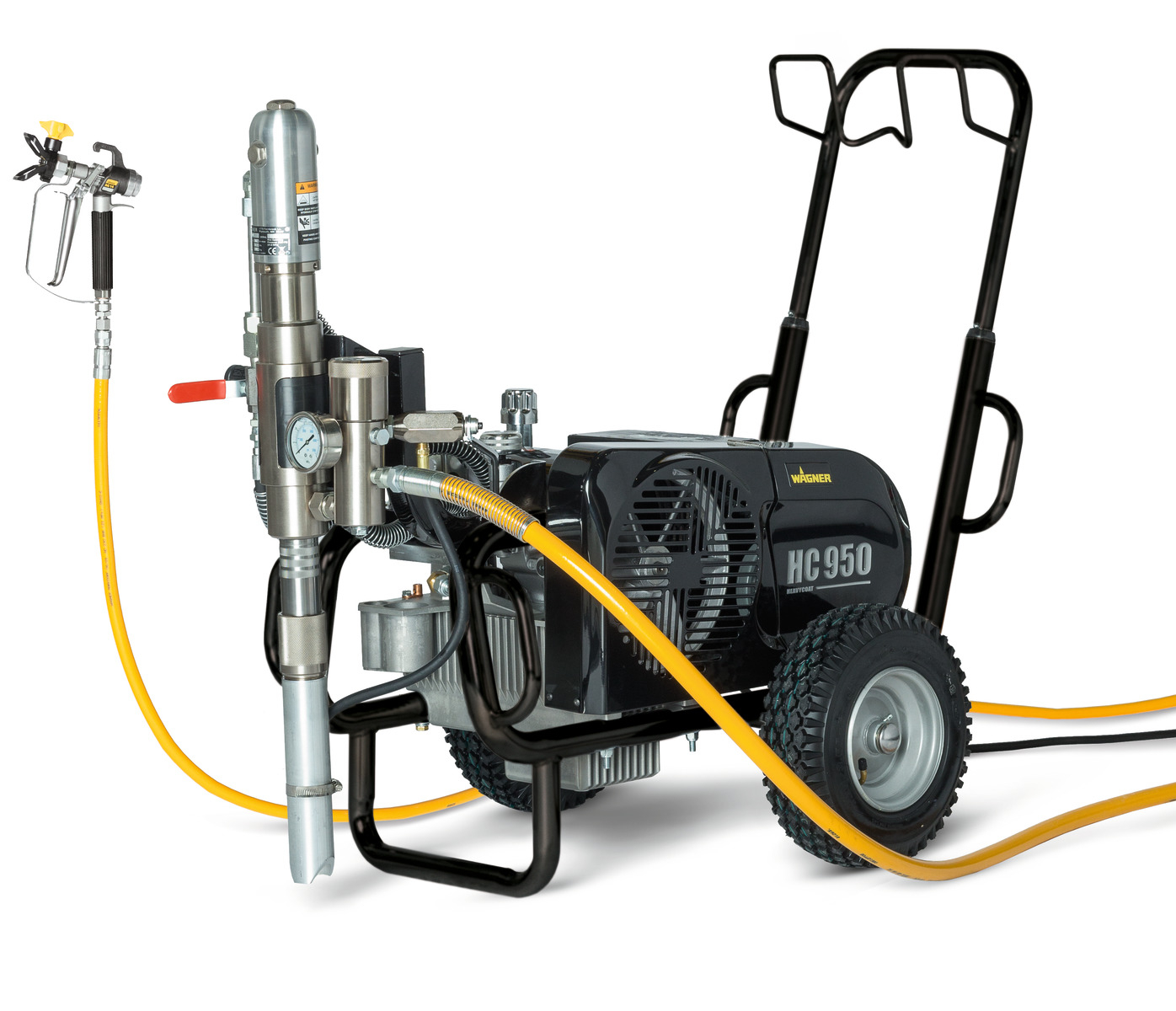
From smaller pumps for lighter work right up to larger pumps for higher viscosity materials, larger work sites or for running multiple guns, you will find the right pump in the Wagner ProSpray range. Features include:
OK, further info: I have talked to an expert on the Wagner pump and he has indicated that the Wagner pumpset, uses a circuit board to simulate solenoids and may not be easily compatible with the sophisticatedly simple solenoid feeds of the EV-300 ACU, (or at least that I may damage the board in the process of finding the correct terminals to connect the EV-300 ACU to.) He suggests that since the Wagner is a reversing high pressure pump that I simple bypass the control box and simply connect the Motor A and Motor B terminals of the ACU on the EV-400 to the 2 feed wires going into the motor on the pumpset.
PLEASE, before I decide which to buy- the EV-400 kit or the EV-300 kit please look at the attached specs/wiring (I down-sized the file by eliminating the hydraulic portions)of the Wagner pumpset and give me your recommendation. If possible I think I might prefer the simplicity of the EV-400 concept (and yes I know how to rewire.) Thanks in advance.


 8613371530291