
what causes hydraulic pump cavitation made in china

The second leading cause of hydraulic pump failure, behind contamination, is cavitation. Cavitation is a condition that can also potentially damage or compromise your hydraulic system. For this reason, understanding cavitation, its symptoms, and methods of prevention are critical to the efficiency and overall health of not just your hydraulic pump, but your hydraulic system as a whole.
The product of excessive vacuum conditions created at the hydraulic pump’s inlet (supply side), cavitation is the formation, and collapse of vapors within a hydraulic pump. High vacuum creates vapor bubbles within the oil, which are carried to the discharge (pressure) side. These bubbles then collapse, thus cavitation.
This type of hydraulic pump failure is caused by poor plumbing, flow restrictions, or high oil viscosity; however, the leading cause of cavitation is poor plumbing. Poor plumbing is the result of incorrectly sized hose or fittings and or an indirect (not straight or vertical) path from the pump to the reservoir. Flow restrictions, for example, include buildup in the strainer or the use of an incorrect length of hose or a valve that is not fully open. Lastly, high oil viscosity—or oil that is too viscous—will not flow easily to the pump. Oil viscosity must be appropriate for the climate and application in which the hydraulic pump is being used.
The greatest damage caused by cavitation results from the excessive heat generated as the vapor bubbles collapse under the pressure at the pump outlet or discharge side. On the discharge side, these vapor bubbles collapse as the pressure causes the gases to return to a liquid state. The collapses of these bubbles result in violent implosions, drawing surrounding material, or debris, into the collapse. The temperature at the point of implosion can exceed 5,000° F. Keep in mind that in order for these implosions to happen, there must be high vacuum at the inlet and high pressure at the outlet.
Cavitation is usually recognized by sound. The pump will either produce a “whining” sound (more mild conditions) or a “rattling” sound (from intense implosions) that can sound like marbles in a can. If you’re hearing either of these sounds, you first need to determine the source. Just because you hear one of these two sounds doesn’t guarantee that your hydraulic pump is the culprit.
To isolate the pump from the power take-off (PTO) to confirm the source, remove the bolts that connect the two components and detach the pump from the PTO. Next, run the PTO with no pump and see if the sound is still present. If not, it is safe to assume your hydraulic pump is the problem.
Another sign you may be experiencing cavitation is physical evidence. As part of your general maintenance, you should be inspecting and replacing the hydraulic oil filter"s elements at regular intervals based on the duty cycle of the application and how often it is used. If at any time during the inspection and replacement of these elements you find metallic debris, it could be a sign that you’re experiencing cavitation in the pump.
The easiest way to determine the health of your complete hydraulic circuit is to check the filter. Every system should have a hydraulic oil filter somewhere in-line. Return line filters should be plumbed in the, you guessed it, return line from the actuator back to tank—as close to the tank as possible. As mentioned earlier, this filter will have elements that should be replaced at regular intervals. If you find metallic debris, your pump could be experiencing cavitation. You’ll then need to flush the entire system and remove the pump for inspection.
Conversely, if you’ve already determined the pump to be damaged, you should remove the filter element, cut it open, and inspect it. If you find a lot of metal, you’ll need to flush the entire system and keep an eye on the other components that may be compromised as a result.
Once cavitation has been detected within the hydraulic pump, you’ll need to determine the exact cause of cavitation. If you don’t, cavitation can result in pump failure and compromise additional components—potentially costing you your system.
Since the pump is fed via gravity and atmospheric pressure, the path between the reservoir and the pump should be as vertical and straight as possible. This means that the pump should be located as close to the reservoir as is practical with no 90-degree fittings or unnecessary bends in the supply hose. Whenever possible, be sure to locate the reservoir above the pump and have the largest supply ports in the reservoir as well. And don"t forget, ensure the reservoir has a proper breather cap or is pressurized (3–5 PSI), either with an air system or pressure breather cap.
Be sure the supply line shut-off valve (if equipped) is fully open with no restrictions. This should be a “full-flow” ball valve with the same inside diameter (i.d.) as the supply hose. If feasible, locate a vacuum gauge that can be T’d into the supply line and plumb it at the pump inlet port. Activate the PTO and operate a hydraulic function while monitoring the gauge. If it reads >5 in. Hg, shut it off, and resume your inspection.
A hose with an inner bladder vulcanized to a heavy spiral is designed to withstand vacuum conditions as opposed to outward pressure. The layline will also denote the size of the hose (i.d.). You can use Muncie Power’s PPC-1 hydraulic hose calculator to determine the optimal diameter for your particular application based on operating flows.
Another consideration, in regards to the inlet plumbing, is laminar flow. To reduce noise and turbulence at the pump inlet, the length of the supply hose should be at least 10 times its diameter. This means that any type of shut-off valve or strainer at the reservoir should be at least 10 diameters from the pump inlet. A flared, flange-style fitting at the pump inlet can also reduce pump noise by at least 50 percent compared to a SAE, JIC, or NPT fitting.
Selecting the proper viscosity of hydraulic fluid for your climate and application is also critical. Oil that is too viscous will not flow as easily to the pump. Consult your local hydraulic oil supplier for help selecting the optimal fluid viscosity.
By maintaining a regular maintenance schedule, remaining vigilant for any signs or symptoms, and taking preventative measures, the good news is that you should be able to prevent cavitation and experience efficient operation for the duration of your pump’s lifespan.
Poor plumbing is the leading cause of cavitation and can be prevented by selecting a properly sized hose, choosing the appropriate fittings, ensuring the most direct, straight routing from the pump to the reservoir, etc.
Two leading causes why hydraulic pumps usually fail are: (1) contamination and (2) cavitation. In order to prevent any potential damage to your entire hydraulic system, it’s imperative to understand cavitation, the indications or symptoms from your system it is occurring, as well as the preventive measures.
How does cavitation happen exactly? It starts when vapor bubbles in the oil are created due to high vacuum. When these vapor bubbles are carried and collapsed on the pump outlet (discharge side), cavitation happens.
Make Sure Oil flow Paths are Straight – Hydraulic pumps are being supplied via atmospheric pressure and gravity, so it’s ideal to place the reservoir above it. Make sure that the path is as straight and vertical as possible. Keep an eye on bent or twisted supply hose.
Check Laminar Flow – If you’re hearing turbulence or noise in pump inlet, make sure that the supply hose length is the correct ratio to its diameter. A flange-style, flared fitting in the pump inlet can also help in eliminating pump noise.
Check Proper Viscosity – It"s important to choose the hydraulic fluid with appropriate viscosity for your application and climate. Consult with your supplier for professional help in choosing the optimal fluid viscosity.
With regular maintenance, keeping an eye on symptoms, and taking preventive measures, you’d be able to avoid cavitation and expect efficient operation from your hydraulic pumps.

Oil viscosity is greatly impacted by the temperature of the oil, with low temperatures causing increases in viscosity which makes it difficult for the oil to reach the pump. Generally, it is best to avoid starting hydraulic systems with oil colder than 40°F (4°C) or putting under load with oil colder than70°F (21°C).
Reservoirs do not always have heaters, especially in the South. Those that do possess available heaters are usually disconnected. Although the damage may not be instantaneous, a pump regularly started using cold oil will eventually fail prematurely.
Investing in a hydraulic oil of high viscosity index base oils with low pour points for wide temperature range applicability, like CITGO’s Mystik® JT-9™ LeakShield® AW Hydraulic Oil, can help prevent such cavitation.
Once a year at minimum, the suction strainer needs to be removed from the reservoir and cleaned. It is prudent to keep in mind that strainers may become blocked for a variety of reasons. If there seems to be a malfunction with a pump—before taking any drastic action, like making replacements—check to ensure nothing has obstructed the suction line.
Every pump has a maximum drive speed. High speeds require higher volumes of oil at the suction ports. If an electric motor is driving the hydraulic pump at speeds over the pump’s rating, you might be gearing up for a crash course in cavitation.
Adequate oil volume is unable to flow into the suction cavity in the pump due to the port’s size, causing the pump to cavitate. Maximum drive speeds can range from as low as 1,200 revolutions per minute (RPM) to as high as 3,600 RPM — so always check drive speed when replacing a pump with that of a different brand or model. Cavitates tend to be rare but being mindful of your pumps’ maximum drive speeds can prevent costly mishaps, such as leaks and other cavitation-induced damage altogether.

Although cavitation can occur anywhere in a hydraulic system, it commonly occurs within the suction line of a pump. This will cause excessive noise in the pump – generally a high pitched “whining” sound. However, this excessive noise is only the tip of the iceberg! The real result of this phenomenon is severe pump damage and a decrease in pump life. I have personally seen many instances where a customer was replacing pumps frequently, thinking they were receiving defective pumps from their vendor. In reality, the pump failures were not due to poor pump quality – the failures were occurring because of cavitation.
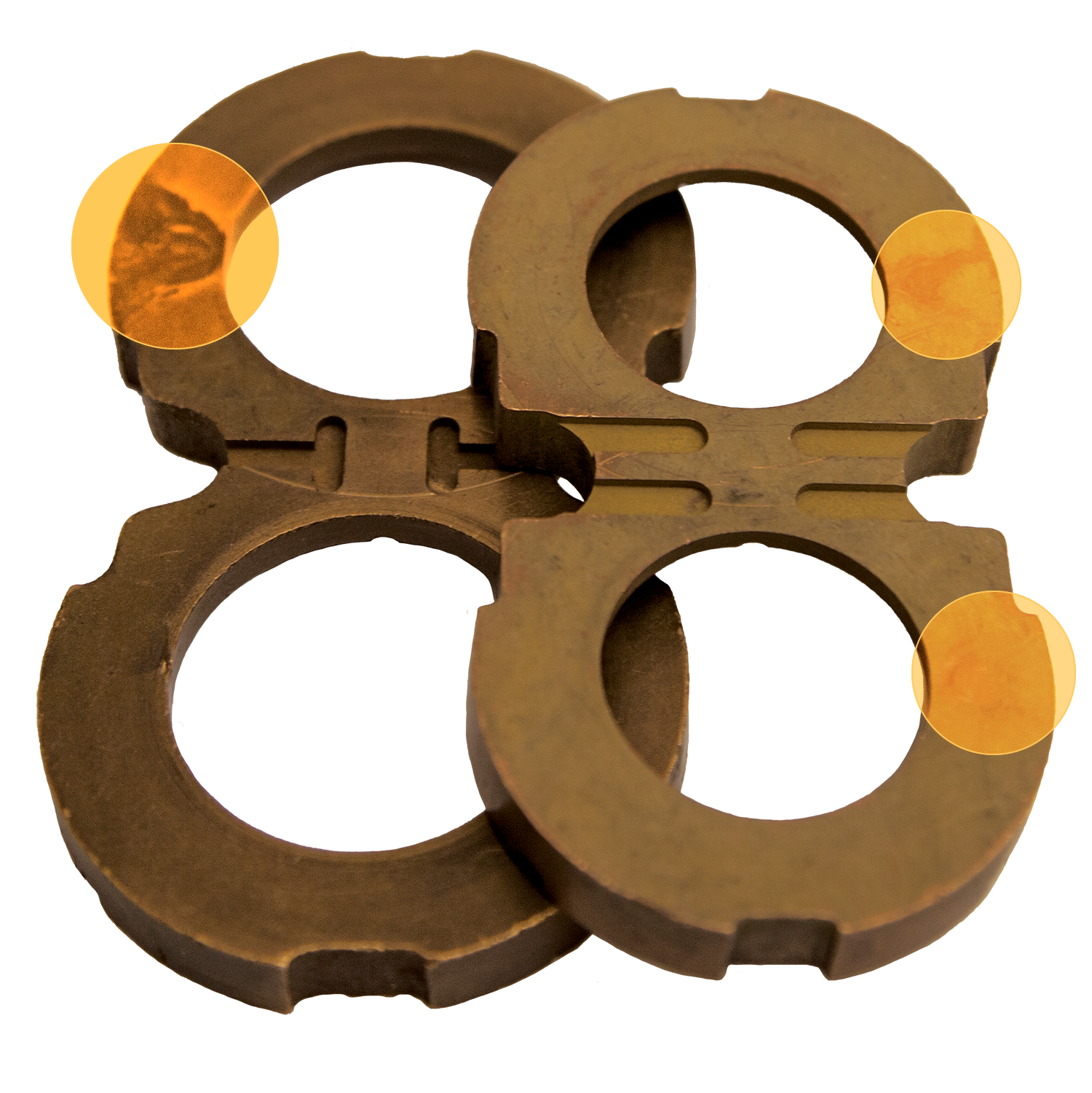
Simply put, cavitation is the formation of vapor cavities in the hydraulic oil. In hydraulic pumps, cavitation will occur any time the pump is attempting to deliver more oil than it receives into the suction (inlet) line. This is commonly referred to as “starvation” and results from a partial vacuum in the suction line. To fully illustrate what is happening when this occurs, we need to discuss vapor pressure. Vapor pressure is the pressure below which a liquid at a given temperature will become a gas, and this pressure varies significantly depending on the liquid. Generally, as the temperature of a liquid rises, the vapor pressure will proportionally increase. Likewise, as the temperature decreases, the vapor pressure will decrease. Most of us know that water will boil (turn to vapor) at 212°F (100°C) at 14.7 PSI (atmospheric pressure at sea level). In other words, the vapor pressure of water at 212°F is 14.7 PSI. If the pressure is reduced, the temperature at which the water boils will be reduced. If the temperature is lowered, the vapor pressure will decrease. In fact, water will boil at room temperature if the pressure is sufficiently reduced! The same principle applies to hydraulic oil, although the vapor pressure will be somewhat different than that of water. The vapor pressure of hydraulic oil is somewhere between 2 and 3 PSI at normal temperatures. In ideal conditions, the pressure in the suction line of the pump will be around 14.7 PSI at sea level. Of course, this pressure decreases with altitude, but sufficient pressure will normally be maintained in the suction line to prevent cavitation of the oil. However, if the pressure in the suction line of the pump is sufficiently reduced to the vapor pressure of the oil, vapor cavities will form. As the oil passes from the suction line to the outlet of the pump, the pressure will increase and the vapor cavities will implode violently. These extremely powerful implosions will cause erosion and premature failure of the pump components. In fact, a brand-new pump can be destroyed in a matter of minutes if the cavitation is severe enough. The picture below shows a rotor and cam ring from a vane pump that had failed due to severe cavitation.
In my 35-plus years of troubleshooting hydraulic components, this is the worst case of cavitation damage I have ever seen. In addition to the usual erosion of the parts, the vanes were actually fused to the rotor slots! Although this is an extreme example, it shows the potential damage to a pump due to cavitation. The good news is that cavitation is preventable and we will look at several conditions that can trigger this phenomenon.
Gaseous and vaporous cavitation is extremely harmful to axial piston pumps, such as reducing flow rate, increasing flow pulsation, increasing vibration, increasing noise, and shortening life. To suppress the cavitation and improve the performance of axial piston pumps, a mathematical model for suppressing cavitation in the plunger chamber with a constant theoretical flow rate is innovatively established by combining the flow equation of the plunger pump and the pressure drop equation of the plunger chamber. Based on the model, two methods to suppress cavitation in the plunger chamber under the condition of a constant theoretical flow rate are proposed. The first method is to increase the distribution circle radius and correspondingly reduce the rotation speed, and the second method is to increase the plunger chamber radius and correspondingly reduce the rotation speed. To verify the effectiveness of these two methods, the CFD model of the axial piston pump is established, and the correctness of the model is verified by experiments. The results show that the two methods can effectively suppress cavitation in the plunger chamber, improve the actual flow rate, and reduce the flow pulsation under the condition of a constant theoretical flow rate. The research results can provide an important reference for the design and optimization of the plunger pump.
Axial piston pumps are one of the positive displacement hydraulic pumps, which can convert mechanical power into hydraulic power. They are widely used in aerospace, machinery, ships, and other fields because of their compact structure, high functional density, high reliability, easy automation, and long life [1, 2].
Cavitation is a dynamic process where vapor bubbles form in the liquid when the localized pressure drops below the vapor pressure and then collapse when the localized pressure rises above the vapor pressure [3, 4]. In recent years, cavitation has been observed in plunger pumps, and the plunger chamber and the relief groove are the main areas where cavitation occurs [5–10]. When the bubbles generated by vaporous cavitation collapse, severe pressure fluctuation, pressure impact, and high-speed jet flow will be generated [11–13], accompanied by vibration and noise [14–18], which will lead to the formation of pits on the metal surface [19, 20]. The hydraulic oil is contaminated by the chipped metal particles, which further causes particle wear, resulting in a decrease in the sealing and load-bearing capacity of the friction pair. The air bubbles generated by the gaseous cavitation destroy the continuity of the oil discharge of the plunger pump, which leads to the reduction of the effective delivery flow rate and the decrease of the volumetric efficiency of plunger pumps [21–23].
Suppressing cavitation in the plunger chamber has always been one of the goals of scholars at home and abroad. Research shows that pressure drop is the main cause of cavitation in the plunger chamber [12, 24]. Two factors cause pressure drop are as follows: the first is the pressure loss along the way during the oil suction process of the plunger chamber [25, 26]. The second is the pressure drop near the center of rotation caused by centrifugal force when the plunger chamber rotates around the shaft [27, 28].
The plunger chamber is the most important hydraulic oil transmission area of the plunger pump. Therefore, the cavitation in the plunger chamber should be suppressed. At present, the main methods for suppressing cavitation in the plunger chamber are as follows: the first method is to increase oil suction pressure. In this method, the initial pressure energy of hydraulic oil is increased by adding a turbine-increasing device at the oil suction port, which prevents the oil pressure from being affected by the energy loss along the way during the oil suction process, and finally achieves the purpose of suppressing cavitation [28, 29]. The second method is to decrease the oil discharge pressure [30]. This method can suppress cavitation by reducing the jet flow and backflow during the high-pressure and low-pressure conversion of the plunger chamber. The third method is to optimize the suction pipeline. This method can effectively reduce the suction pressure drop and achieve the purpose of suppressing cavitation by keeping the oil suction direction of the oil suction pipeline consistent with the tangential velocity direction of the plunger chamber [31–33]. The fourth method is to reduce the rotation speed. The method can suppress cavitation in the plunger chamber by reducing pressure difference and increasing the pressure near the inside wall of the plunger chamber [12, 34]. The fifth method is to reduce the swash plate inclination angle. The method can reduce the oil suction force by reducing the relative axial speed, thereby reducing the energy loss along the way and suppressing cavitation in the plunger chamber [35].
Although some achievements have been made in suppressing cavitation in the plunger chamber, there are still some shortcomings. For example, the theoretical flow rate will decrease when decreasing the rotation speed or decreasing the swash plate inclination angle.
Faced with the problem that reducing the rotation speed or decreasing the swash plate inclination angle will reduce the theoretical flow rate, in this paper, the pressure drop equation of the plunger chamber is deduced, and by combining the theoretical flow equation of the plunger pump and the pressure drop equation of the plunger chamber, the pressure drop model of the plunger chamber with an invariable theoretical flow rate is innovatively established. Based on this model, the measures to suppress cavitation in the plunger chamber with a constant theoretical flow rate are proposed and verified. The results can provide an important reference for suppressing cavitation in the plunger chamber.
During the operation of the plunger pump, the viscosity and compressibility can be ignored because the hydraulic oil flow rate is extremely fast and the oil will not be subject to the high pressure during the normal oil suction process. Consider a fluid particle P that flows from the suction port to the plunger chamber. For inviscid flow, Euler’s equations can be expressed in vector notation as
Because the plunger chamber pressure drop model needs to be studied from an analytical equation point of view, the hydraulic oil flow is assumed to be steady state.
Because the axial piston pump is a rotating fluid machine, the Cartesian coordinate system should be converted into a cylindrical coordinate system. The origin and -axis of the cylindrical coordinate system coincide with the origin and -axis of the Cartesian coordinate system, respectively. Figure 1 shows the schematic diagram of the oil location in the plunger chamber. The blue coordinate is the local coordinate system, the distance between the fluid particle in the plunger chamber and the origin of the cylindrical coordinate system is , and the distance between the fluid particle and the origin of the local coordinate system is . According to the geometric structure of the plunger pump and the rotating cylindrical coordinate system, can be expressed as
where is the integral constant. Considering two situations of hydraulic oil, the first is when the fluid particle flows from the valve plate into the cylinder block, and the second is when the fluid particle reciprocates in the plunger chamber, and the following two expressions can be obtained according to Equation (10).
where is the axial velocity of the plunger. The inlet pressure can be obtained if the flow resistance from the pump inlet to the valve-plate suction port is neglected.
The relationship between the pressure at an arbitrary location in the plunger chamber and the pressure at the suction port of the plunger pump can be expressed as
In order to suppress cavitation in the plunger chamber, it is necessary to increase the pressure in the plunger chamber by reducing the pressure drop coefficient .
Although the cavitation in the plunger chamber can be effectively suppressed by reducing the rotation speed, reducing the swash plate inclination angle, reducing the distribution circle radius, and reducing the plunger chamber radius, the theoretical flow rate, the most key parameter of a plunger pump, will decrease by these methods to suppress cavitation. To solve this problem, it is necessary to suppress cavitation in the plunger chamber based on the constant theoretical flow rate. Because the flow rate of the axial piston pump is determined by the flow rate of a single plunger chamber, the theoretical flow rate formula of a single plunger chamber is introduced here.
Because the theoretical flow rate of the axial piston pump is not affected by , is considered. Through simplification, the theoretical flow formula of a single plunger chamber can be expressed as
Figure 2 shows the relationship curves between the distribution circle radius , the rotation speed , and the variable pressure drop term . Figure 3 shows the projected contour plot of the variable pressure drop term on the plane, and the black solid line is the relationship curve between the distribution circle radius and the rotation speed under the condition of constant oil discharge flow rate in this paper. Under the premise of , the variable pressure drop term decreases as the distribution circle radius increases. Therefore, under the condition of the constant theoretical flow rate, the cavitation in the plunger chamber can be suppressed by increasing the distribution circle radius and correspondingly reducing the rotation speed.
Figure 4 shows the relationship curves between the plunger chamber radius , the rotation speed , and the variable pressure drop term . Figure 5 shows the projected contour plot of the variable pressure drop term on the plane, and the black solid line is the relationship curve between the plunger chamber radius and the rotation speed under the condition of a constant oil discharge flow rate. Under the premise of , the variable pressure drop term c6 decreases as the plunger chamber radius increases. Therefore, under the condition of a constant theoretical flow rate, the cavitation in the plunger chamber can be suppressed by increasing the plunger chamber radius and correspondingly reducing the rotation speed.
Flow pulsation is one of the key indicators to evaluate the performance of the axial plunger pump. Assuming is the flow pulsation, then can be expressed as
Figure 6 shows the fluid domain model and mesh model of the plunger pump. Because there is relative motion among the components of the axial piston pump during operation, the fluid domain of the piston pump is divided into 5 parts: inlet, outlet, inlet of valve plate, outlet of valve plate, and plunger chamber. To accurately locate the position of the plunger chamber, the plunger chamber is divided into four areas according to the order in which the hydraulic oil is sucked, which are the chamber window area, the chamber overflow area, the chamber expansion and compression area and the chamber top area. Table 1 shows the parameters of the fluid domain of the plunger pump. The type of the relief groove is a triangular relief groove, and the type of the pump is a 9-piston variable displacement axial piston pump.
Figure 7 shows the fluid domain and mesh motion diagram of the plunger chamber. The fluid domain of the axial piston pump is divided by the Cartesian grid, which has the advantages of high accuracy, fast speed, less grid quantity demand, and high flow field resolution. The meshed parts are connected by a Mismatched Grid Interface (MGI), which is treated as the common face connecting cells on both sides of the interface. During the simulation process, the interface is the same as an internal interface between two neighboring cells in the same grid domain.
The boundary conditions and fluid properties for the CFD model are shown as in Figure 6 and Table 2. During the operation of the plunger pump, the pressure, flow rate, and cavitation of the fluid will change with time. Therefore, the simulation type is unsteady, and the plunger chamber rotates by 1° in each iteration step. Before the simulation is started, the internal flow field of the plunger pump is in a static state, and after the simulation is started, the flow field is in a turbulent state. After the plunger chamber rotates 13 times, the simulation results gradually become stable. Therefore, the total iteration step in this paper is 5400 steps, that is, the plunger chamber rotates 15 times in total. All the simulation results in this paper are the results after the flow field becomes stable. In the simulation model, the full cavitation model is selected as the cavitation model, and the standard k-ɛ turbulence model is selected as the turbulence model.
In the study of suppressing cavitation in the plunger chamber, the characteristic parameters include the peak value of the gas phase volume fraction of the plunger chamber, the valley value of the flow rate, and the peak value of the flow rate. Figure 8 shows the variation curves of three characteristic parameters with the number of grids. When the number of grids is more than 500000, three characteristic parameters become stable. Therefore, to ensure the accuracy of the simulation results, the number of grids is 800000.
To verify the correctness of the simulation model, the flow rate of the plunger pump under the conditions of different pressures and rotation speeds is tested, and the tested axial plunger pump is shown in Figure 9.
Figure 10 shows the comparison of the theoretical flow rate, simulation flow rate and experimental flow rate of the plunger pump when is equal to 0.5 Mpa. Figure 11 shows the relative error between theoretical results and simulation results; Figure 12 shows the relative error between simulation results and experiment results. From the point of view of pressure and rotation speed, the simulation flow rate is basically consistent with the experimental flow rate, the relative error between theoretical results and simulation results does not exceed 5% and the relative error between the simulation results and the experimental results does not exceed 3.5%, which verifies the correctness of the simulation model of the plunger pump. The difference between the theoretical flow rate and the simulation flow rate increases with the increase of pressure, which is caused by the aggravation of backflow. The difference between the theoretical flow rate and the experimental flow rate increases with the increase of pressure, which is caused by the aggravation of backflow and leakage. The difference between the theoretical flow rate, the simulation flow rate, and the experimental flow rate increases with the increase of the rotation speed, which is caused by the increased cavitation caused by the increase of the rotation speed.
In order to study the cavitation suppression in the plunger chamber based on distribution circle radius and rotation speed, 6 groups of data of distribution circle radius and rotation speed are selected, and the data are shown in Table 3.
Figure 13 shows the curves of the gas phase volume fraction in the plunger chamber with different distribution circle radii and rotation speeds. Under the condition of a constant theoretical flow rate, the gas phase volume fraction in the plunger chamber decreases with the increase of the distribution circle radius. When the distribution circle radius increases from 0.036735 m to 0.047334 m, the peak value of the gas phase volume fraction in the plunger chamber decreases from 5.638% to 4.138%, and the average gas phase volume fraction decreases from 1.080% to 0.963%. Figure 14 shows the curves of the vapor volume fraction in the plunger chamber with different distribution circle radii and rotation speeds. Under the condition of a constant theoretical flow rate, with the increase of the distribution circle radius and the corresponding decrease of the rotation speed, the vapor volume fraction in the plunger chamber decreases. When the distribution circle radius increases from 0.036735 m to 0.047334 m and the rotation speed decreases from 1984.5 r/min to 1540.125 r/min, the vapor volume fraction in the plunger chamber decreases from 0.139% to zero. To sum up, under the condition of a constant theoretical flow rate, the gaseous cavitation and vaporous cavitation in the plunger chamber can be effectively suppressed by increasing the distribution circle radius and correspondingly reducing the rotation speed.
Figure 15 shows the flow rate curves of the outlet port with different distribution circle radii and rotation speeds. With the increase of the distribution circle radius and the corresponding decrease of the rotation speed, the peak values of the outlet port flow rate decrease and the valley values increase, which plays the role of “cutting the peak and filling the valley.” Under the condition of a constant theoretical flow rate, when the distribution circle radius increases from 0.036735 m to 0.047334 m, the peak value of the flow rate decreases from 1.642 kg/s to 1.432 kg/s, and the valley value increases from 0.474 kg/s to 0.972 kg/s. Figure 16 shows the average oil discharge flow rate curve and flow pulsation rate curve with different distribution circle radii and rotation speeds. By increasing the distribution circle radius, the cavitation in the plunger chamber can be suppressed, and the backflow and jet flow rate can be reduced, thereby increasing the actual flow rate and reducing the flow pulsation. When the distribution circle radius increases from 0.036735 m to 0.047333 m, the actual flow rate increases from 1.164 kg/s to 1.201 kg/s, and the flow pulsation rate decreased from 4.564% to 1.153%. To sum up, the actual flow rate can be effectively increased and the flow pulsation can be reduced by increasing the distribution circle radius and correspondingly reducing the rotation speed.
In order to study the cavitation suppression of the plunger chamber based on plunger chamber radius and rotation speed, 6 groups of data of plunger chamber radius and rotation speed are selected, and the data are shown in Table 4.
Figure 17 shows the curves of the gas phase volume fraction in the plunger chamber with different plunger chamber radii and rotation speeds. Under the condition of a constant theoretical flow rate, the gas phase volume fraction in the plunger chamber decreases with the increase of the plunger chamber radius. When the plunger chamber radius increases from 0.00925 m to 0.0105 m, the peak value of the gas phase volume fraction decreases from 6.348% to 4.010%, and the average gas phase volume fraction decreases from 1.186% to 0.942%. Figure 18 shows the curves of the vapor volume fraction in the plunger chamber with different plunger chamber radii and rotation speeds. Under the condition of a constant theoretical flow rate, with the increase of the plunger chamber radius and the corresponding decrease of the rotation speed, the vapor volume fraction in the plunger chamber decreases. When the plunger chamber radius increases from 9.25 mm to 10.5 mm, the vapor volume fraction decreases from 3.74% to zero. To sum up, under the condition of a constant theoretical flow rate, the gaseous cavitation and vaporous cavitation in the plunger chamber can be effectively suppressed by increasing the plunger chamber radius and correspondingly reducing the rotation speed.
Figure 19 shows the flow rate curves of the outlet port with different plunger chamber radii and rotation speeds. With the increase of the plunger chamber radius and the corresponding decrease of the rotation speed, the peak values of the outlet port flow rate decrease and the valley values increase, which plays the role of “cutting the peak and filling the valley.” When the plunger chamber radius increases from 0.00925 m to 0.0105 m, the peak value of the oil discharge flow rate decreases from 1.66 kg/s to 1.49 kg/s, and the valley value increases from 0.49 kg/s to 0.83 kg/s. Figure 20 shows the average oil discharge flow rate carve and flow pulsation curve with different plunger chamber radii and rotation speeds. By increasing the plunger chamber radius and correspondingly reducing the rotation speed, the filling rate of the plunger chamber is increased and the backflow is reduced because the cavitation in the plunger chamber is suppressed, thereby increasing the actual flow rate and reducing the flow pulsation rate. When the plunger chamber radius increases from 0.00925 m to 0.0105 m, the actual flow rate increases from 1.157 kg/s to 1.194 kg/s, and the flow pulsation rate decreases from 4.7% to 1.7%. To sum up, under the condition of a constant theoretical flow rate, by increasing the plunger chamber radius and correspondingly reducing the rotation speed, the cavitation in the plunger chamber can be effectively suppressed, the oil discharge flow rate is increased, and the flow pulsation rate is reduced, which can improve the stability and prolong the life of pumps.
In this paper, the axial piston pump is taken as the research object, and the research on suppressing cavitation, reducing flow pulsation, and increasing the actual flow rate is carried out by theoretical analysis, numerical calculation, and experimental test. By deriving the pressure drop equation of the plunger chamber considering the window pressure loss, it is found that the cavitation of the plunger chamber can be suppressed by reducing the swash plate inclination angle, reducing the cylinder rotation speed, reducing the distribution circle radius, and reducing the plunger chamber radius. However, the theoretical flow rate will be reduced when these methods are used to suppress cavitation in the plunger chamber, which has no practical engineering significance. In order to suppress the gaseous cavitation and vaporous cavitation in the plunger chamber under the condition of a constant theoretical flow rate, a model for suppressing cavitation in the plunger chamber with a constant theoretical flow rate is innovatively established by combining the flow equation of the plunger pump and the pressure drop equation of the plunger chamber. Based on this model, two methods for suppressing cavitation in the plunger chamber with an invariable theoretical flow rate are proposed. The first method is to increase the distribution circle radius and correspondingly reduce the rotation speed. The second method is to increase the plunger chamber radius and correspondingly reduce the rotation speed. Through the numerical calculation of the CFD model of the plunger pump and the flow rate test of the plunger pump at different pressures and speeds, the effectiveness of the two methods in suppressing cavitation of the plunger chamber, increasing the actual flow rate, and reducing the flow pulsation is further verified. The two methods of suppressing cavitation in the plunger chamber have important reference significance for the design and manufacture of axial plunger pumps.
Hydraulic machineries (i.e., pump, turbine, and reversible pump-turbine) must be often operated in cavitation conditions. Cavitation is one of the major challenges limiting the safe and stable operation of electric power systems (i.e., pumps, turbines), especially in sediment-laden flows where the synergy of cavitation and sediment erosion will cause even more severe damages. According to the literature (Naidu, 2016; Sharma and Singh, 1987; Naidu, 1996; Wang et al., 2022), cavitation has shown to be the major cause of metal loss at pump/hydropower stations, particularly in South Asian countries belonging to Himalayan regions (such as India, China, and Nepal), where large contents of quartz exist in the sediment especially during the monsoon season (Singhal and Ratnendra, 2017). The synergy effects of cavitation and sediment erosion are important and result in more severe damage (Thapa et al., 2007; Teran et al., 2018), as shown in Figures 1, 2. In China, the total annual sediment yield of the main rivers was 4.77 × 10⁹ tons in 2020 (Ministry of Water Resources of the People’s Republic of China, 2020), and pumps or turbines are prone to experience cavitation and thus even serious erosion due to the synergistic effects of cavitation and sediment erosion (Huang, 1991) when operated in sediment-laden rivers. This problem is a major concern in the case of small and mini hydropower plants, which have been developed quickly in recent years. According to the literature, 40% of the turbines in the built hydropower station in China experience serious synergistic effects of cavitation and sediment erosion (Yang, 2012), ultimately leading to economic losses (i.e., the efficiency and life reduction and operation and maintenance costs of the turbine).
FIGURE 1. Erosion in the hydro turbine for (A) the needle with pure cavitation erosion, (B) the needle with synergy of cavitation and sand erosion, and (C) turbine runner with synergy of cavitation and sand erosion shown in the enlarged picture (Thapa et al., 2007).
FIGURE 2. Erosion damage in the components of three Francis turbines: (A) hard-particle erosion in one of the covers, (B) cavitation damage at the trailing edge of one of the runner blades, and (C) synergistic damage of the hard particles and cavitation at the leading edge of the runner blades (Teran et al., 2018).
Hydrodynamic cavitation generally occurs if the local static pressure drops below the saturated vapor pressure, and consequently, the negative pressures are relieved by means of forming gas-filled or gas- and vapor-filled cavities (i.e., evaporation) (Knapp et al., 1970; Arndt, 1981; Brennen, 1995). Vapor structures are transported into high static pressure areas by the flow, and the subsequent collapse of vapor regions will generate shock waves, which can cause vibrations and noise (Brennen, 1994). Near solid boundaries, the collapse of vapor structures often leads to severe damage of surface material, i.e., pitting or erosion (Knapp et al., 1970; Arndt, 1981; Brennen, 1994; Brennen, 1995). The synergism of cavitation and sediment erosion, which occurs in high-speed regions, including guide vanes and runner blade inlet of a turbine and pump in hydraulic machinery, generally consists of two interrelated processes: 1) high-speed impact on the solid walls of sediment particles carrying kinematic energy and 2) the collapse of cavitation bubbles, and their combined effects, such as cavitation-induced acceleration of the solid particles impinging the surface (Arndt et al., 1989; Kumar and Saini, 2010). Cavities in liquid flows will experience unsteady processes, i.e., cavity formation, growth, and collapse, which could significantly change the motions of nearby sediment particles, acting on the sediment erosion process known as cavitation enhancement. Meanwhile, the existence of sediment particles alters the cavity behaviors from cavity inception and development to the cavity collapse process, influencing the cavitation erosion. This is a challenging problem, and complex phenomena including gas/vapor-liquid-solid three-phase flows, mass transfer, compressibility, turbulence, unsteadiness, and material properties as well, where the physical understanding is very limited and requires further investigation. With the development of modern hydraulic machinery toward large-scale, large-capacity, high-speed, and high-performance directions, the synergistic effects of cavitation and sediment erosion are becoming a serious problem, and the lack of physics and mechanisms involved significantly limits the reliability, stability, and safe operation of hydraulic machinery in sediment-laden flows.
Cavitation in sediment-laden flows is complex gas/vapor-liquid-solid three-phase turbulent flows. So far, despite plenty of research work on cavitation erosion (Tomita and Shima, 1986; Berchiche et al., 2002; Sreedhar et al., 2017) and sediment erosion (Padhy and Saini, 2008; Padhy and Saini, 2009), theoretical work on the synergy mechanism of cavitation and sediment erosion is very scarce. For example, Rao and Buckley (Rao and Buckley, 1984) reviewed erosion models for both long-term cavitation and liquid impingement proposed by different investigators, including the curve fitting approach and a power-law relationship. They also evaluated the importance of the different modeling methods using data from cavitation fields and a liquid impingement device. As for the prediction of synergy effects of cavitation and sediment erosion. Ni and He (Ni and He, 1994) theoretically investigated the impact of shock waves generated by the bubble collapse on the solid particles considering the liquid compressibility, and the maximum velocities of solid particles were obtained. The Gilmore equation was used to calculate the bubble radius and the particle motion was calculated by solving the Newton equation. Their study showed that the shockwave-induced speed of particles was large enough to cause damage to the concretes used in hydraulic structures. Duan (Duan, 1998) carried out experimental and theoretical work to investigate the erosion performance under different flow velocities, and found that when above certain flow rate, cavitation would protect the solid walls of flow passage from being eroded, thus weakening the erosion process. Inspired by this experiment, Li (Li, 2006) proposed a microscopic model based on the assumption that the particle near the cavitation bubbles will be trapped by the microjet of the collapsing bubble and accelerated to an extremely high velocity towards the solid walls, resulting in potential damage. That is,
Recently, based on an effective-medium approach where the influence of effective suspension viscosity on bubble/particle dynamics and the impact energy of erosive particles were incorporated, (Su et al., 2021) developed a theoretical model to predict the synergistic erosion of cavitation and sediment particles by taking into account the dual effects of sediment particles (i.e., viscosity effect of small particles and inertial effects of large particles) in a large range of sediment sizes. Good agreement between the model prediction and experimental data was found. This theoretical model could predict the opposing effects of sediment parties on the cavitation erosion as well, and showed that the viscous effect of sediment-sized particles (STP, < 50 μm) could mitigate or even override the impact of impinging microjets and sand-sized particles (SDP, > 50 μm).
Teran et al., (2021) developed a synergy model to predict the wear behavior of combined effect of cavitation and particle erosion where the impact velocity of a particle trapped by the microjet of a collapsing bubble near a solid wall was estimated, and implemented this model into the CFD software. Their model was validated with the experimental results obtained by a slurry pot erosion tester and showed good agreement. In this model, the impact velocity of the particle (Vp) which is accelerated towards the wall by a collapsing bubble is as follows
In summary, the above theoretical studies reveal that the accurate prediction of impact loads generated by the collapsing cavitation bubbles or cavity structures and maximum sediment particle velocity is critical for the evaluation of synergy of cavitation and sediment erosion. Physical models have been mainly established on the dynamics, such as pressure loads, of the collapsing bubbles and its influence on nearby particle motions, such as microscopic model. In addition, the gas/vapor-liquid-solid three-phase cavitation mixture properties (i.e., viscosity) provides interesting perspective for the understanding and prediction of synergy of cavitation and sediment erosion in sediment-laden flows. On the basis of theoretical results, an in-depth and detailed knowledge on cavitation in sediment-laden flows could be obtained, which greatly contributes to the suppression of synergy of cavitation and sediment erosion and improvement of hydraulic machine performance.
Experiment has always been an important way for understanding the physics and mechanism behind the synergy of cavitation and sediment erosion. Experimental investigations of synergistic effects of cavitation and sediment erosion have been designed and conducted by using both laboratory and field experiments. So far, the laboratory studies on synergy of cavitation and sediment erosion are generally based on small-scale models (i.e., foil, cylinder, venturi, rotating risk, and impeller) to accelerate cavitation erosion testing with vibratory apparatus (i.e., Figure 3) (Huang et al., 1996; Wu and Gou, 2013; Zhao et al., 2017; Teran et al., 2018; Wang et al., 2018; Stella and Alcivar, 2019; Su et al., 2021), rotating disc systems (i.e., Figure 4) (Rasmussen, 1956; Lichtman, 1967; Wood et al., 1967; Thapa et al., 2007; Hong et al., 2013; Steller and Gireń, 2015), slurry pot testers (i.e., Figure 5) (Amarendra et al., 2012; Peng et al., 2020), and water tunnel (i.e., Figure 6) (Liu, 1983; Gregorc et al., 2011; Gregorc et al., 2012). In the following, these devices used in the laboratory studies are explained briefly.
FIGURE 5. Slurry pot test (Amarendra et al., 2012). (A) Photograph of the specimen holder of the modified slurry pot test setup; (B) drawing of the cavitation inducers; (C) schematic diagram of the specimen holder with section at A-A; (D) positioning of the CIs and the specimen. A—CI, B—cylindrical specimen, C—lower base plate, D—distance between specimen and cavitation inducer and E—hole for clamping the bolt.
Using vibratory test facilities, a number of studies have provided detailed quantification of the synergistic effects of cavitation and sediment erosion. For example, Huang et al. (Huang et al., 1996) conducted systematic experiments to study the effects of particle properties on cavitation and sediment erosion to understand the synergy mechanism in solid-water mixtures using vibratory test facilities. The damaged patterns of specimen surfaces were measured by SEM photographs, and the vibratory cavitation erosion test was guided by ASTM D32-77 (ASTM D32-77, 1977). Su et al., (2021) employed the vibratory test facility to investigate the effects of microparticles in synergistic cavitation-particle erosion in a flat-bottomed Perspex vessel as shown in Figure 3. In this study, the test samples including vibrating horn tip and four-bladed impeller were all fabricated from medium carbon steel (AISI 1045, density 7.87 × 10³ kg m−3). The microparticle with median diameters of approximately 45 μm and 90 μm were tested. Romero et al., (2019) experimentally investigated the effects of particle sizes and sediment concentrations on the synergy between cavitation and solid particle erosion with a modified ultrasonic cavitation tribometer. The test material was AISI 316 stainless steel with a hardness of 223.3 ± 4.9 HV, and the optical stereoscopy and scanning electron microscopy were used to analyze the surface wear. The sand particles used were from the penstock of the Amaime 152 hydroelectric plant with the size distribution ranging between 50 μm and 150 μm, and the hardness of 775.9 ± 124.2 HV. Chen et al., (2022b) investigated the erosion characteristics of 6063 aluminum specimens in sandy water containing quartz sand which has sharp edges and irregular shapes under different sediment sizes and concentrations using the ultrasonic vibration cavitation apparatus to understand the mechanism involved in the synergy of cavitation and sediment erosion. Chen et al., (2007) investigated the effects of microparticles with different sizes on cavitation erosion using the tip surface testing and free radical detection where after the experiment, the tip surface was examined by the Wyko MHT-III optical interferometer. The rotating speed was 15,000 r/min for 10 min. Their study showed that particles at a certain size would increase the number of heterogeneous nucleation while weaken bubble-particle interactions.
The cavitating rotating disk resembles the pump impeller that is well suitable for the study of cavitation erosion in hydraulic machinery, and high intensity cavitating flows can be obtained. As presented in Figure 4, the rotating disk device consists of a disk with pins or holes at various radii (Steller and Gireń, 2015), and cavitation bubbles are generated and collapsed by the movement of the pins or holes in the disk through the ambient stationary liquid. Using the rotary disk cavitation system which can consider the centrifugal force in rotary hydraulic machines (i.e., pump and turbine), Wang et al., (2008) investigated the microparticles and their size on cavitation erosion process. In this study, the dimensions of the sample were 40 × 30 × 6 mm, and material of the sample was the Q235 steel without heat treatment. The diameter of the rotating disk was 300 mm, and the rotating speed of the disk was 2800 r/min in the experiments at room temperature.
Amarendra et al., (2012) studied the synergy of slurry erosion and cavitation erosion using a slurry pot tester. A schematic of this test is shown in Figure 5. The slurry pot has a circular section with a diameter of 282 mm and a height of 286 mm, with the diameters of the upper and lower circular ring plates of 150 mm and a thickness of 4 mm. The size of the sand particles is between 210 μm and 354 μm, and the concentration is 10 wt%. Weight loss was measured using a Mettler Toledo electronic balance (model AB-104S) with a least count of 0.1 mg. Sato et al., (1991) experimentally studied coupled damage caused by sediment erosion (i.e., artificial sediment (Al2O3)) and cavitation erosion using the submerged cavitating jet experimental apparatus. The magnitude of the acoustic emission energy, impact pressure and material damage rate caused by cavitating jet impingement were carefully examined.
In addition to the synergy effects of cavitation and sediment erosion experiments using simple geometry models, experiments have also been conducted on proto pumps and turbines (Zhou et al., 2013; Lu et al., 2014; Wang et al., 2014; Zhao et al., 2017; Liu et al., 2019), and even the field experiments have been conducted in hydroelectric power and pump stations (Yang et al., 2005; Lu et al., 2019). Specifically, Takagi et al., (1978) experimentally studied the influence of alumina concentration on the performance and cavitation characteristics of turbines. Mei and Wu, (1996) conducted experiments to study the effect of solid particles on different model Francis turbines and observed earlier cavitation inception in sandy water. Jin et al., (1986) carried out an experiment to investigate the role of sand particles on the combined effects of cavitation and sediment erosion of hydraulic turbines, and the 18Cr-8Ni steel was tested in a venturi device at a hydroelectric power station in the flood season. In their work, two types of damage: 1) smooth erosion in the area of regular fluid flow and 2) in the regions where cavitation occurred, were studied, and the sand particles, cavities, cracks, and cutting scar sand fatigue patterns on the sponge-like worn surface were observed. Thapa et al. (Thapa et al., 2007) investigated the combined effects of cavitation and sediment erosion in hydraulic turbines on a rotary disk apparatus. Their study showed that the combined effects of cavitation and sediment erosion were stronger than the individual effects. Using the hydraulic machinery erosion testing system at the China Institute of Water Resources and Hydropower Research (CIWRH), China, which has three test modes including venturi-section water tunnel, rotating disc and rotating disc with jet nozzle (Lu et al., 2014; Liu et al., 2019; Hydraulic Machinery, 2021), as shown in Figures 7, 8, Lu et al., (2014) experimentally studied the synergetic erosion caused by cavitation and sand erosion in hydraulic machinery. A high-precision electronic analytical balance (maximum capacity: 220 g, readability: 0.1 mg) was used to measure the weight loss, and a 3D surface profiler was used to image the erode surface as well as the volume loss. Furthermore, Figure 9 shows the Francis turbine test rig under construction at Turbine Testing Tab (TTL) at Kathmandu University, which has been used for hydropower development, especially the problem of sediments in the design and operation of hydraulic machineries in the Himalayan region (Thapa et al., 2007; Thapa et al., 2012a; Thapa et al., 2012b).
FIGURE 7. Photograph of the hydraulic machinery abrasion testing system at the China Institute of Water Resources and Hydropower Research (Hydraulic Machinery, 2021).
The majority of abovementioned experimental work in the synergy of cavitation and sediment erosion is summarized in Table 1. Here we come up with a brief summary of these experiment work. These results show that the synergy of cavitation and sediment erosion causes more severe damages than the individual effects of pure cavitation or pure sediment erosion, respectively. The dual effects of sediment on cavitation erosion (i.e., acceleration and inhibition) are observed on both laboratory and field studies, and mainly depend on the sediment size, concentration, and material properties. Research has illustrated that with increasing sediment size and concentration, the synergy of cavitation and sediment erosion experiences a plateau value, which indicates a critical sediment size and concentration value in terms of synergy of cavitation and sediment erosion. Furthermore, the coexistence of sediment and bubbles will alter significantly the local flow structures, i.e., high pressure region, faster bubble collapse, moments and noises in cavitating flows, and bubble-particle collisions also reduce the number of free bubbles, which could change the cavity structures. The detailed discussion about the influence of sediment on synergy of cavitation and sediment erosion will be presented in the following section.
Compared with experimental measurements and theoretical modelings, the numerical simulations can predict local flow structures and dynamics associated with synergistic effects of cavitation and sediment particles, and promote the understanding of combined effects of cavitation and sediment erosion. Up to now, the prediction and prevention of the combined effects of cavitation and sediment erosion in hydraulic practice are still limited by the lack of physical understanding of flow structures and dynamics of cavitation in sediment-laden flows, and the corresponding responses of solid materials. With the advancement in computational power, computational fluid dynamics (CFD) method has been extensively used to predict and design the cavitating flows to prevent the potential erosion in hydraulic machinery in sediment-laden rivers (i.e., Figure 10).
Specifically, Dunstan and Li, (2010) carried out a numerical study on cavitation enhancement of sediment erosion using commercial code STAR-CCM+ and a simplified analytical approach in MATLAB. The micromodel proposed by Li, (2006) which considered a single sediment particle entrained in the micro-jet of collapsing cavitation bubbles was used to calculate the particle energy potential gained from the collapsing bubble and thus the erosion distribution. Simulation results supported the mechanism of the Li’s micromodel (Li, 2006) that the particle damage potential would be enhanced by the microjet generated in the process of bubble collapse, and further showed that this enhancement is mainly associated with the mass of particle and ratio between the distance from the collapsing bubble to a solid boundary and its radius upon collapse.
Weili et al., (2010) numerically studied cavitation characteristics in both pure water and solid-liquid two-phase flow conditions in a Kaplan turbine. The Singhal cavitation model (Singhal et al., 2002) was used to calculate the phase change between vapor phase and liquid phase. In their study, a particle trajectory model was used to investigate the region and degree of runner blade erosion in different operation conditions. The study found that compared with the efficiency with two phases cavitation in clean water of 89.52%, the efficiency was 87.84% in sediment flow, decreasing by 1.68%.
Gregorc et al., (2011) studied the impact of solid particles on the development of cavitation flow around a hydrofoil using an inhomogeneous model where an addition phase particle dispersion model (Euler-Euler) was used. Numerical modeling was performed using the commercial CFD program ANSYS-CFX 12.1 while considering the impact of particles. The results showed that the hydrodynamic forces on the hydrofoil were significantly influenced by mass fraction of particles in water, and the changes in the mass fraction of particles ξ = 0.0032 led to a change of the ratio of moments Mt/Mt0 up to 11%. The increase in the vapor phase in the case of the dispersed phase mass fraction is 0.0032 and the shear velocity is 0.876 compared with pure water. Figure 11 presents a comparison of the vapor volume fraction simulation without particles and with particles under different conditions.
Wang et al., (2014) numerically investigated the influence of the solid particle content on the cavitation characteristics of a centrifugal pump by combining the numerical calculations and the test results, and revealed that with an increase in the solid particle content, the cavitation would be worsened. The simulations were conducted on ANSYS-CFX using an inhomogeneous mixture multiphase model and Singhal cavitation model (Singhal et al., 2002) to calculate the solid-liquid-vapor three-phase flows. The particle size is 100 μm with different particle concentrations of 10%, 20%, and 30%.
Kumar and Bhingole, (2015) employed numerical simulations to investigate the combined erosion in a Kaplan turbine rated capacity of 7 MW using ANSYS 14 software. The computational domain was constructed from the casing inlet to the draft tube outlet, where 15 aero wicket gates and five runner blades were used, and the unstructured tetrahedral mesh was generated. The 3D viscous flow simulation with the SST k-ɷ turbulence model has been conducted. The operation conditions used in the simulation including pure water, cavitation erosion, sediment erosion and a combined erosion model at 100% wicket gate opening with varying sediment size and sediment concentration were investigated. The results showed that under the combined erosion operation, the combined erosion rate and nonuniformity increased with the increasing in sediment diameter and sediment concentration. The maximum efficiency drop of 4.31 pct and the maximum normalized average combined erosion of 0.00329 g g−1 were found at 100 μm sediment diameter and 10,000 ppm sediment concentration.
Sun et al., (2022) numerically investigated the effects of sediment diameter and concentration on synergistic cavitation and sediment erosion mechanisms in cavitating flows around a rotating disk using ANSYS-CFX code. The non-homogeneous multiphase flow model with the modified RNG k-ε turbulence model and Zwart-Gerber-Belamri cavitation model was employed to simulate the bubble-particles interaction of solid-liquid-gas three-phase flow. In the simulation, sediment is considered as the dispersed solid particles, and water and vapor are regarded as continuous fluids. The sediment size is in the range of 20–400 μm and sediment concentration is in the range of 1%–10%. They concluded that with an increase in sediment particle size, the cavitation is first inhibited and then promoted where both the cavitation area and intensity are enhanced, and with increasing sediment particle concentration, the cavitation is always promoted where the cavitation area is expanded and cavitation intensity remains the same.
Although few numerical studies have been conducted on the synergy effects of cavitation and sediment erosion of cavitation in sediment-laden flows, the cavitation or air bubble behaviors when interacting with solid walls and particles have been studied using CFD numerical simulations (Johnsen and Colonius, 2009; Jayaprakash et al., 2012; Zhang et al., 2016; Teran et al., 2018; Chen et al., 2022a). For example, Johnsen and Colonius, (2009) numerically simulated the collapsing behaviors of a non-spherical gas bubble induced by a shock wave in a free field near a solid surface, and showed that the shock induced collapse would generate a high velocity reentrant jet, which created a water hammer shock and produced high pressures on the neighboring walls, leading to potential damage. In their study, they used a high-order WENO scheme for the accurate shock- and interface-capturing, and the numerical results were validated by the available theory and experiments. Teran et al., (2018) employed the combined experiments and numerical simulations to investigate the interactive behavior of hard particles and cavitation bubbles near a solid wall to deepen the understanding of synergistic effects of particle erosion and cavitation damage using the commercial software ANSYS-FLUENT solver. In their simulation, the Volume-Of-Fluid (VOF) model was used to capture the evolution of the interface between air and liquid water, and the six degree-of-freedom solver coupled with a dynamic mesh was used to model the interaction between the particle and the fluid. Figure 12 shows the comparisons of an image sequence obtained experimentally and the contour lines of air volume fraction showing the bubble interface obtained using CFD simulations. Red represents air, while blue color represents water. The data were obtained for a maximum bubble size (Rb) of 2.5 mm, distance to wall of 1.5 mm, particle diameter of 60 μm, and particle material sand.
The abovementioned simulation work illustrates the state-of-art of numerical approaches and physical models describing the gas/vapor-liquid-solid complex three-phase flows, showing that simulation is an important tool to deepen the knowledge and understanding of cavitation in sediment-laden flows. The complex turbulence flows a


 8613371530291