
what causes hydraulic pump failure free sample
When a hydraulic system fails, finding the source of the problem can be a challenge. Though hydraulic systems primarily consist of a sump, motor, pump, valves, actuators and hydraulic fluid, any of these parts could be the source of failure. That"s not to mention the additional potential for failure through human error and faulty maintenance practices. If your system fails, you need to know why it fails, how to find the failure and how to keep it running smoothly in the future, all while keeping personnel safe.
It"s often easy to tell when a hydraulic system fails — symptoms can include high temperatures, low pressure readings and slow or erratic operation are glaring problems. But what are the most common causes of hydraulic systems failures? We can trace most hydraulic issues back to a few common causes, listed below.
Air and water contamination are the leading causes of hydraulic failure, accounting for 80 to 90% of hydraulic failures. Faulty pumps, system breaches or temperature issues often cause both types of contamination.
Air contamination is the entrance of air into a hydraulic system and consists of two types — aeration and cavitation. Both can cause severe damage to the hydraulic system over time by wearing down the pump and surrounding components, contaminating hydraulic fluids and even overheating the system. Although we are not pump manufacturers, we know it is essential to be aware of these types of contamination and how to identify their symptoms.
Cavitation:Hydraulic oil consists of about 9% dissolved air, which the pump can pull out and implode, causing pump problems and damage to the pump and to other components in a hydraulic system over time. You can identify this problem if your hydraulic pump is making a whining noise.
Aeration:Aeration occurs when air enters the pump cavity from an outside source. Usually, loose connections or leaks in the system cause this issue. Aeration also creates a sound when the pump is running, which sounds like knocking.
Water contamination is also a common problem in hydraulic systems, often caused by system leaks or condensation due to temperature changes. Water can degrade hydraulic components over time through oxidation and freeze damage. A milky appearance in hydraulic fluid can help you identify water contamination.
Fluid oxidization: Extreme heat can cause hydraulic fluid to oxidize and thicken. This fluid thickening can cause buildups in the system that restrict flow, but can also further reduce the ability of the system to dissipate heat.
Fluid thickening:Low temperatures increase the viscosity of hydraulic oil, making it harder for the oil to reach the pump. Putting systems under load before the oil reaches 70 degrees or more can damage the system through cavitation.
Fluid levels and quality can affect hydraulic system performance. Low fluid levels and inappropriate filtration can result in air contamination, while fluid contamination can cause temperature problems. Leaks can further exacerbate both issues.
Using the correct type of fluid is also essential, as certain hydraulic oils are compatible with specific applications. There are even oil options that offer higher resistance to temperature-related problems. Some oils even offer anti-wear and anti-foam additives to help prevent against wear and air contamination, respectively.
Human error is the base cause of many hydraulic system problems. Some of the most common errors that may result in your hydraulic pump not building pressure include the following.
Faulty installations: Improper installation of any component in a hydraulic system can result in severe errors. For example, the pump shaft may be rotating in the wrong direction, negatively affecting pressure buildup, or pipes may be incorrectly fitted, resulting in leaks.
Incompatible parts: An inexperienced installer may put mismatched components together, resulting in functional failures. For example, a pump may have a motor that runs beyond its maximum drive speed.
Improper maintenance or usage:Using systems outside their operational capabilities or failing to perform regular maintenance are some of the most common causes of hydraulic system damage, but are easy to rectify through updated maintenance policies and training.
The sources of system failures can be tricky to identify, but some hydraulic troubleshooting steps can help narrow down the options. So how do you troubleshoot a hydraulic system? Here are some of the fundamentals.
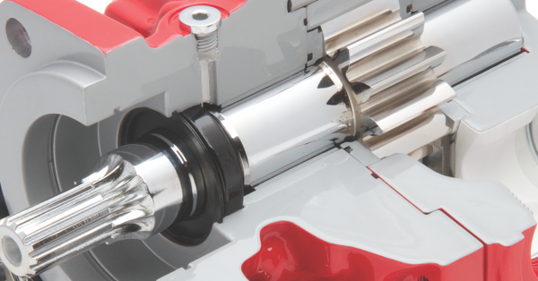
Check the pump: Take the pump assembly apart and assess all parts to ensure that they are functional and installed correctly. The most common problem areas include the pump shaft, coupling and filter.
Check the fluids:Check the level, color and viscosity of the hydraulic oil to ensure it meets specifications and has not become contaminated. Low hydraulic fluid symptoms include pressure or power loss. When in doubt, drain and replace the fluids.
Check the seals: Look for evidence of any fluid leakage around your hydraulic system"s seals, especially the shaft seal. Leakage can indicate worn-out or blown seals that can cause malfunctions with pumps, motors and control valves.
Check the filters: Ensure filters are clear of plugs and blockages. Common clogged hydraulic filter symptoms include sluggish operation and noisy operation.
Run the system: When you have completed all these essential checks, turn on the system and monitor it for pressure and temperature fluctuations, as well as abnormal sounds. If all seems well, check your pressure sensor for potential failure.
Hydraulic system issues are inevitable at some point. However, simple steps can help you avoid these issues and increase the longevity of your hydraulic system. On top of effective troubleshooting, you can prevent hydraulic system failure by taking the following steps.
Follow specifications: We can trace the most common hydraulic system issues back to fundamental system problems like incompatible or improperly installed parts. For this reason, it"s essential to always double-check specifications to ensure your purchased parts can work together seamlessly.
Consult with professionals: When purchasing new equipment, consult with industry peers and professionals to discover what they recommend. While manufacturers can tell you how a product should work, industry professionals can provide concrete examples of how well the equipment works for their industry.
On top of these steps, look into hydraulic system products that are specifically designed to help prevent failures. One such product is Bear-Loc® by York Precision. This innovative locking actuator is a safe, reliable feature for hydraulic components, automatically locking when sleeve pressure is relieved, preventing movement if a hydraulic system fails. This way, your can protect your personnel from injuries related to hydraulic failures. Even better, York Precision offers in-house design, engineering expertise and machining and manufacturing capabilities to produce a hydraulic locking device that meets your exact specifications.
Regularly review hydraulic system maintenance, always following manufacturer recommendations and industry best practices. Also, consider the storage condition, external influences, working pressure and usage frequency of your system to tailor your maintenance schedule and procedures.
Daily tasks:Take care of a few simple daily checks to avoid issues. For example, personnel should check the oil levels, hoses and connections and listen to the pump for abnormal sounds.
Routine tasks:Plan and execute a weekly and monthly maintenance routine, checking for the most common failure sources given your system"s working conditions. These should include components, filters and the condition of the oil.
Be mindful of location:Do not stand at endpoints while working on hydraulic systems. This safety measure can help prevent loss of limb and life, as there is a lot of pressure built up in these areas that can release and result in life-threatening situations.
The best safety measures, however, are to perform excellent maintenance and use high-quality parts. If you"re looking for a quality hydraulic component manufacturer, York Precision Machining & Hydraulics can help.

Hydraulic pumps are at the core of many essential factory operations. Unfortunately, there are numerous pitfalls to plan for, mitigate, and overcome to keep them running. Keeping up on routine maintenance is important, but the best way factory techs can avail themselves of costly, frustrating breakdowns is to understand the various catalysts for hydraulic pump failure.
The simplest way to identify the cause of pump failure is to thoroughly inspect and dissect the aftermath of the problem. In most cases, the cause of failure will be evident by the nature of the catalyst(s). Here are eight of the most common problems, some of their defining features, and how they ultimately come to fruition.
1. Fluid contamination is one of the biggest causes of hydraulic pump damage and involves debris mixing with the liquid. This debris causes friction, leading to extenuated wear on the pump itself. The result is inefficiency, culminating in malfunction.
2. Fluid viscosity issues occur when the hydraulic fluid within a pump breaks down over time. Viscosity that’s too high leads to cavitation (another catalyst for damage). Subsequently, if a tech changes and replaces fluid with a viscosity that’s too low, heat and friction become concerns.
3. Over-pressurization occurs because of excessive load on the pump itself, resulting in red-line operation that’s both unsafe and damaging. Hydraulic pumps operating under high duress for extended periods of time will likely experience component wear and premature failure, usually in spectacular fashion.
4. Excess heat can be a product of poor fluid viscosity or environmental factors. This issue is rarely a singular catalyst for pump breakdown, but it exacerbates other factors or masks other issues, such as fluid contamination.
5. Implosion invariably results in extreme failure for hydraulic pumps and is a major safety hazard. Implosion occurs when air bubbles within a hydraulic pump collapse, causing an overload of pressure to the pump that generates an intense shock.
6. Aeration occurs when hydraulic fluid traps air bubbles. The pump subjects the bubbles to pressure, causing high heat and over-pressurization when the bubbles collapse. Aeration at extreme levels leads to implosion.
7. Pump aeration pertains to air not in the hydraulic fluid, but air introduced through unsealed joints or shafts. This air quickly causes pressure instability affecting crucial parts of the pump. This can quickly lead to breakdowns — generally marked by a whine or other high-pitched sound.
8. Cavitation is a symptom of uncontrolled pump speeds, which fail to allow hydraulic fluid to completely fill the pump. It results in destabilized pressure, heat, and excess wear. Cavitation is often marked by the same type of whine or squeal as pump aeration.
Because the factors causing each of these problems differ in nature, it’s best to fully evaluate a damaged hydraulic pump to determine if more than one issue is responsible.
Maintenance is the best approach for ensuring safe, efficient hydraulic pump function. But routine service is just the start. Identifying common issues plaguing your hydraulic pumps will lead to a better quality of targeted maintenance — for example, if you pinpoint a heat issue related to viscosity, that issue may be resolved by opting for a different fluid weight.
Every piece of information learned about your pumps can translate into better care, leading to longer uptimes, fewer issues, and fundamentally better maintenance.
Having trouble identifying the catalysts for your hydraulic pump’s issues? Let the professionals at Global Electronic Services take a look! Contact us for all your industrial electronic, servo motor, AC and DC motor, hydraulic, and pneumatic needs — and don’t forget to like and follow us on Facebook!

Check that the pump shaft is rotating. Even though coupling guards and C-face mounts can make this difficult to confirm, it is important to establish if your pump shaft is rotating. If it isn’t, this could be an indication of a more severe issue, and this should be investigated immediately.
Check the oil level. This one tends to be the more obvious check, as it is often one of the only factors inspected before the pump is changed. The oil level should be three inches above the pump suction. Otherwise, a vortex can form in the reservoir, allowing air into the pump.
What does the pump sound like when it is operating normally? Vane pumps generally are quieter than piston and gear pumps. If the pump has a high-pitched whining sound, it most likely is cavitating. If it has a knocking sound, like marbles rattling around, then aeration is the likely cause.
Cavitation is the formation and collapse of air cavities in the liquid. When the pump cannot get the total volume of oil it needs, cavitation occurs. Hydraulic oil contains approximately nine percent dissolved air. When the pump does not receive adequate oil volume at its suction port, high vacuum pressure occurs.
This dissolved air is pulled out of the oil on the suction side and then collapses or implodes on the pressure side. The implosions produce a very steady, high-pitched sound. As the air bubbles collapse, the inside of the pump is damaged.
While cavitation is a devastating development, with proper preventative maintenance practices and a quality monitoring system, early detection and deterrence remain attainable goals. UE System’s UltraTrak 850S CD pump cavitation sensor is a Smart Analog Sensor designed and optimized to detect cavitation on pumps earlier by measuring the ultrasound produced as cavitation starts to develop early-onset bubbles in the pump. By continuously monitoring the impact caused by cavitation, the system provides a simple, single value to trend and alert when cavitation is occurring.
The oil viscosity is too high. Low oil temperature increases the oil viscosity, making it harder for the oil to reach the pump. Most hydraulic systems should not be started with the oil any colder than 40°F and should not be put under load until the oil is at least 70°F.
Many reservoirs do not have heaters, particularly in the South. Even when heaters are available, they are often disconnected. While the damage may not be immediate, if a pump is continually started up when the oil is too cold, the pump will fail prematurely.
The suction filter or strainer is contaminated. A strainer is typically 74 or 149 microns in size and is used to keep “large” particles out of the pump. The strainer may be located inside or outside the reservoir. Strainers located inside the reservoir are out of sight and out of mind. Many times, maintenance personnel are not even aware that there is a strainer in the reservoir.
The suction strainer should be removed from the line or reservoir and cleaned a minimum of once a year. Years ago, a plant sought out help to troubleshoot a system that had already had five pumps changed within a single week. Upon closer inspection, it was discovered that the breather cap was missing, allowing dirty air to flow directly into the reservoir.
A check of the hydraulic schematic showed a strainer in the suction line inside the tank. When the strainer was removed, a shop rag was found wrapped around the screen mesh. Apparently, someone had used the rag to plug the breather cap opening, and it had then fallen into the tank. Contamination can come from a variety of different sources, so it pays to be vigilant and responsible with our practices and reliability measures.
The electric motor is driving the hydraulic pump at a speed that is higher than the pump’s rating. All pumps have a recommended maximum drive speed. If the speed is too high, a higher volume of oil will be needed at the suction port.
Due to the size of the suction port, adequate oil cannot fill the suction cavity in the pump, resulting in cavitation. Although this rarely happens, some pumps are rated at a maximum drive speed of 1,200 revolutions per minute (RPM), while others have a maximum speed of 3,600 RPM. The drive speed should be checked any time a pump is replaced with a different brand or model.
Every one of these devastating causes of cavitation threatens to cause major, irreversible damage to your equipment. Therefore, it’s not only critical to have proper, proactive practices in place, but also a monitoring system that can continuously protect your valuable assets, such as UE System’s UltraTrak 850S CD pump cavitation senor. These sensors regularly monitor the health of your pumps and alert you immediately if cavitation symptoms are present, allowing you to take corrective action before it’s too late.
Aeration is sometimes known as pseudo cavitation because air is entering the pump suction cavity. However, the causes of aeration are entirely different than that of cavitation. While cavitation pulls air out of the oil, aeration is the result of outside air entering the pump’s suction line.
Several factors can cause aeration, including an air leak in the suction line. This could be in the form of a loose connection, a cracked line, or an improper fitting seal. One method of finding the leak is to squirt oil around the suction line fittings. The fluid will be momentarily drawn into the suction line, and the knocking sound inside the pump will stop for a short period of time once the airflow path is found.
A bad shaft seal can also cause aeration if the system is supplied by one or more fixed displacement pumps. Oil that bypasses inside a fixed displacement pump is ported back to the suction port. If the shaft seal is worn or damaged, air can flow through the seal and into the pump’s suction cavity.
As mentioned previously, if the oil level is too low, oil can enter the suction line and flow into the pump. Therefore, always check the oil level with all cylinders in the retracted position.
If a new pump is installed and pressure will not build, the shaft may be rotating in the wrong direction. Some gear pumps can be rotated in either direction, but most have an arrow on the housing indicating the direction of rotation, as depicted in Figure 2.
Pump rotation should always be viewed from the shaft end. If the pump is rotated in the wrong direction, adequate fluid will not fill the suction port due to the pump’s internal design.
A fixed displacement pump delivers a constant volume of oil for a given shaft speed. A relief valve must be included downstream of the pump to limit the maximum pressure in the system.
After the visual and sound checks are made, the next step is to determine whether you have a volume or pressure problem. If the pressure will not build to the desired level, isolate the pump and relief valve from the system. This can be done by closing a valve, plugging the line downstream, or blocking the relief valve. If the pressure builds when this is done, there is a component downstream of the isolation point that is bypassing. If the pressure does not build up, the pump or relief valve is bad.
If the system is operating at a slower speed, a volume problem exists. Pumps wear over time, which results in less oil being delivered. While a flow meter can be installed in the pump’s outlet line, this is not always practical, as the proper fittings and adapters may not be available. To determine if the pump is badly worn and bypassing, first check the current to the electric motor. If possible, this test should be made when the pump is new to establish a reference. Electric motor horsepower is relative to the hydraulic horsepower required by the system.
For example, if a 50-GPM pump is used and the maximum pressure is 1,500 psi, a 50-hp motor will be required. If the pump is delivering less oil than when it was new, the current to drive the pump will drop. A 230-volt, 50-hp motor has an average full load rating of 130 amps. If the amperage is considerably lower, the pump is most likely bypassing and should be changed.
Figure 4.To isolate a fixed displacement pump and relief valve from the system, close a valve or plug the line downstream (left). If pressure builds, a component downstream of the isolation point is bypassing (right).
The most common type of variable displacement pump is the pressure-compensating design. The compensator setting limits the maximum pressure at the pump’s outlet port. The pump should be isolated as described for the fixed displacement pump.
If pressure does not build up, the relief valve or pump compensator may be bad. Prior to checking either component, perform the necessary lockout procedures and verify that the pressure at the outlet port is zero psi. The relief valve and compensator can then be taken apart and checked for contamination, wear, and broken springs.
Install a flow meter in the case drain line and check the flow rate. Most variable displacement pumps bypass one to three percent of the maximum pump volume through the case drain line. If the flow rate reaches 10 percent, the pump should be changed. Permanently installing a flow meter in the case drain line is an excellent reliability and troubleshooting tool.
Ensure the compensator is 200 psi above the maximum load pressure. If set too low, the compensator spool will shift and start reducing the pump volume when the system is calling for maximum volume.
Performing these recommended tests should help you make good decisions about the condition of your pumps or the cause of pump failures. If you change a pump, have a reason for changing it. Don’t just do it because you have a spare one in stock.
Conduct a reliability assessment on each of your hydraulic systems so when an issue occurs, you will have current pressure and temperature readings to consult.
Al Smiley is the president of GPM Hydraulic Consulting Inc., located in Monroe, Georgia. Since 1994, GPM has provided hydraulic training, consulting and reliability assessments to companies in t...
The second leading cause of hydraulic pump failure, behind contamination, is cavitation. Cavitation is a condition that can also potentially damage or compromise your hydraulic system. For this reason, understanding cavitation, its symptoms, and methods of prevention are critical to the efficiency and overall health of not just your hydraulic pump, but your hydraulic system as a whole.
The product of excessive vacuum conditions created at the hydraulic pump’s inlet (supply side), cavitation is the formation, and collapse of vapors within a hydraulic pump. High vacuum creates vapor bubbles within the oil, which are carried to the discharge (pressure) side. These bubbles then collapse, thus cavitation.
This type of hydraulic pump failure is caused by poor plumbing, flow restrictions, or high oil viscosity; however, the leading cause of cavitation is poor plumbing. Poor plumbing is the result of incorrectly sized hose or fittings and or an indirect (not straight or vertical) path from the pump to the reservoir. Flow restrictions, for example, include buildup in the strainer or the use of an incorrect length of hose or a valve that is not fully open. Lastly, high oil viscosity—or oil that is too viscous—will not flow easily to the pump. Oil viscosity must be appropriate for the climate and application in which the hydraulic pump is being used.
The greatest damage caused by cavitation results from the excessive heat generated as the vapor bubbles collapse under the pressure at the pump outlet or discharge side. On the discharge side, these vapor bubbles collapse as the pressure causes the gases to return to a liquid state. The collapses of these bubbles result in violent implosions, drawing surrounding material, or debris, into the collapse. The temperature at the point of implosion can exceed 5,000° F. Keep in mind that in order for these implosions to happen, there must be high vacuum at the inlet and high pressure at the outlet.
Cavitation is usually recognized by sound. The pump will either produce a “whining” sound (more mild conditions) or a “rattling” sound (from intense implosions) that can sound like marbles in a can. If you’re hearing either of these sounds, you first need to determine the source. Just because you hear one of these two sounds doesn’t guarantee that your hydraulic pump is the culprit.
To isolate the pump from the power take-off (PTO) to confirm the source, remove the bolts that connect the two components and detach the pump from the PTO. Next, run the PTO with no pump and see if the sound is still present. If not, it is safe to assume your hydraulic pump is the problem.
Another sign you may be experiencing cavitation is physical evidence. As part of your general maintenance, you should be inspecting and replacing the hydraulic oil filter"s elements at regular intervals based on the duty cycle of the application and how often it is used. If at any time during the inspection and replacement of these elements you find metallic debris, it could be a sign that you’re experiencing cavitation in the pump.
The easiest way to determine the health of your complete hydraulic circuit is to check the filter. Every system should have a hydraulic oil filter somewhere in-line. Return line filters should be plumbed in the, you guessed it, return line from the actuator back to tank—as close to the tank as possible. As mentioned earlier, this filter will have elements that should be replaced at regular intervals. If you find metallic debris, your pump could be experiencing cavitation. You’ll then need to flush the entire system and remove the pump for inspection.
Conversely, if you’ve already determined the pump to be damaged, you should remove the filter element, cut it open, and inspect it. If you find a lot of metal, you’ll need to flush the entire system and keep an eye on the other components that may be compromised as a result.
Once cavitation has been detected within the hydraulic pump, you’ll need to determine the exact cause of cavitation. If you don’t, cavitation can result in pump failure and compromise additional components—potentially costing you your system.
Since the pump is fed via gravity and atmospheric pressure, the path between the reservoir and the pump should be as vertical and straight as possible. This means that the pump should be located as close to the reservoir as is practical with no 90-degree fittings or unnecessary bends in the supply hose. Whenever possible, be sure to locate the reservoir above the pump and have the largest supply ports in the reservoir as well. And don"t forget, ensure the reservoir has a proper breather cap or is pressurized (3–5 PSI), either with an air system or pressure breather cap.
Be sure the supply line shut-off valve (if equipped) is fully open with no restrictions. This should be a “full-flow” ball valve with the same inside diameter (i.d.) as the supply hose. If feasible, locate a vacuum gauge that can be T’d into the supply line and plumb it at the pump inlet port. Activate the PTO and operate a hydraulic function while monitoring the gauge. If it reads >5 in. Hg, shut it off, and resume your inspection.
A hose with an inner bladder vulcanized to a heavy spiral is designed to withstand vacuum conditions as opposed to outward pressure. The layline will also denote the size of the hose (i.d.). You can use Muncie Power’s PPC-1 hydraulic hose calculator to determine the optimal diameter for your particular application based on operating flows.
Another consideration, in regards to the inlet plumbing, is laminar flow. To reduce noise and turbulence at the pump inlet, the length of the supply hose should be at least 10 times its diameter. This means that any type of shut-off valve or strainer at the reservoir should be at least 10 diameters from the pump inlet. A flared, flange-style fitting at the pump inlet can also reduce pump noise by at least 50 percent compared to a SAE, JIC, or NPT fitting.
Selecting the proper viscosity of hydraulic fluid for your climate and application is also critical. Oil that is too viscous will not flow as easily to the pump. Consult your local hydraulic oil supplier for help selecting the optimal fluid viscosity.
By maintaining a regular maintenance schedule, remaining vigilant for any signs or symptoms, and taking preventative measures, the good news is that you should be able to prevent cavitation and experience efficient operation for the duration of your pump’s lifespan.
Poor plumbing is the leading cause of cavitation and can be prevented by selecting a properly sized hose, choosing the appropriate fittings, ensuring the most direct, straight routing from the pump to the reservoir, etc.
The pump is the most expensive and critical component in any hydraulic system—it works by first creating a vacuum at the pump inlet, which generates atmospheric pressure. Liquid from the reservoir tank is then propelled through the inlet line to the pump, past a hydraulic filter or strainer, and into the hydraulic system. On a macro-level, the mechanical energy of the pump’s gears is transferred through fluid “flow” and used to power the attached hydraulic machinery.
Although hydraulic systems can be used in many everyday objects, they’re usually best suited for products that require high-power density or systems with changing load requirements. This simple yet elegant design offers exceptional consistency and speed compared to other driving mechanisms. Hydraulic systems are widely used across industries because they are reliable, easy to maintain, long-lasting, and safe. But despite their many advantages, hydraulic systems still require some degree of maintenance. The following guide explains what can make a hydraulic pump fail, as well as tips for extending its useful lifespan as much as possible.
Fluid contamination is the leading cause of pump failure and usually happens when particulates circulate through the system via a breather valve or cylinder rod, or as a result of repairs, welding slag, sealant, or refilling. Once contaminants enter the system, they can degrade parts, create buildup, change the fluid’s physical and chemical properties, corrode equipment, and lower the system’s overall efficiency.
Hydraulic pumps are designed to work within a specific pressure range. If pressures exceed the pump’s rating, it will likely overburden the pump, cause damage, and eventually halt operations completely. If the pressure changes are extreme, it could even cause an explosion.
Joints and shafts must be completely sealed for the hydraulic pump to work properly. If air gets trapped inside the system, bubbles can cause pressure and temperature fluctuations, which eventually will cause the pump to break down. Usually the first sign there’s air in the pump is a high-pitched whine.
Cavitation occurs when the pump speed is inconsistent, creating air bubbles that rapidly form and then collapse. When this happens, the pump won’t completely fill with fluid, which destabilizes pressure in the system and produces the same type of high-pitched squeal as pump aeration. A blocked pipe, clogged filter, or poor system design can all cause cavitation.
Hydraulic systems need high-quality cooling and lubrication oil with the right mineral content and viscosity. Purity is particularly important for high-pressure systems that operate with larger loads.
The best way to prevent hydraulic pump failure is to inspect and maintain your hydraulic system. Hydraulic filters and strainers will help you avoid fluid contamination, which in turn will stabilize the temperature and pressure inside the system. Filters remove particulates that are smaller than 50 microns, and strainers work tangentially to remove contaminants larger than 50 microns. Various options are available for both filters and strainers using different ratings, mesh sizes, and materials.
After they’re installed, filters and strainers need to be routinely checked and cleaned. Operators should familiarize themselves with their hydraulic system to identify any aberrant conditions as soon as possible, if problems should arise. If you maintain your hydraulic system, it will work more efficiently, necessitate fewer repairs, require less downtime, and last as long as possible.
With over 60 years of experience manufacturing high-quality suction filters, suction strainers, gauges, and diffusers for hydraulic systems, the experts at DOMS Incorporated have the expertise to keep your operation in peak condition. We’ve worked closely with organizations from many industries, including construction, forestry, mining, energy development, industrial manufacturing, aircraft equipment manufacturing, plant processing, and more.

Things like restrictions and blockages can impede the flow of fluid to your pump. which could contribute to poor fluid flow. Air leak in suction line. Air present in the pump at startup. Insufficient supply of oil in pump. Clogged or dirty fluid filters. Clogged inlet lines or hoses. Blocked reservoir breather vent. Low oil in the reservoir
Now that we’ve ensured that the directional control is not reversed, it’s time to check that the drive motor itself is turning in the right direction. Sometimes incorrect installation leads to mismatched pipe routings between control valves and motors, which can reverse the direction of flow. Check to see that the motor is turning the pump in the right direction and if not - look at your piping.
Check to ensure that your pump drive motor is turning over and is developing the required speed and torque. In some cases, misalignment can cause binding of the drive shaft, which can prevent the motor from turning. If this is the case, correct the misalignment and inspect the motor for damage. If required, overhaul or replace motor.
Check to ensure the pump to motor coupling is undamaged. A sheared pump coupling is an obvious cause of failure, however the location of some pumps within hydraulic systems makes this difficult to check so it may go overlooked
It is possible that the entire flow could be passing over the relief valve, preventing the pressure from developing. Check that the relief valve is adjusted properly for the pump specifications and the application.
Seized bearings, or pump shafts and other internal damage may prevent the pump from operating all together. If everything else checks out, uncouple the pump and motor and check to see that the pump shaft is able to turn. If not, overhaul or replace the pump.
If your pump is having problems developing sufficient power, following this checklist will help you to pinpoint the problem. In some cases you may find a simple solution is the answer. If your pump is exhibiting any other issues such as noise problems, heat problems or flow problems, you may need to do some more investigation to address the root cause of your pump problem. To help, we’ve created a downloadable troubleshooting guide containing more information about each of these issues. So that you can keep your system up and running and avoid unplanned downtime. Download it here.
Hydraulic systems are used in a wide range of applications and industries, from automobiles and farm equipment to construction and oil refining. At the heart of any hydraulic system are hydraulic motors and hydraulic pumps. These key components ensure the hydraulic fluid moves through the system to deliver the desired performance to complete the task at hand.
Yet, over time, you can start to notice a decline in performance. When this happens, it is essential to determine the cause and address it before it potentially causes damage to a wider range of hydraulic parts and components in your system.
Uncovering the source of pump failure and hydraulic problems requires you to know how the system is supposed to work and perform at peak efficiency. Having this knowledge is vital to know when things are not working correctly.
Overheating– Overheating can occur for many reasons, such as the hydraulic fluid is not being cooled, there are fluid leaks, or relief valves are stuck closed so the fluid is not recycling.
Aeration of l – If air gets into hydraulic oil and the system, it can cause all sorts of problems, from a loss of power to damaging hydraulic motors and pumps.
Contamination of the Oil – If dirt, dust, debris, or other particles get into the oil, it can damage the pump and system. While a small amount of contaminants are common, your system should have filters to remove most particles.
Implosion – This problem is when there are air bubbles in the fluid. As they travel through the pump, they collapse, release the air and increase pressure inside the system, and result in shock waves that can damage the pump.
Aging– The age of the hydraulic pump, motor, and other parts and components can result in system problems and system fails. Everything does eventually wear out and will need to be replaced.
Once you notice a problem with the hydraulic system, you should perform some hydraulic troubleshooting tests to see if you can determine the source of the problem. These tests can be broken down into sound tests and visual tests.
What does the system sound like when it operates normally? Unusual sounds indicate something is wrong in the system. You want to pay attention to the sounds being made and where they are coming from to help determine what part or component is not working correctly.
Does it sound like gravel or marbles are moving around inside the ? This sound indicates aeration problems where air is getting into the hydraulic oil. It may also be accompanied by a periodic whining sound.
Is the hydraulic motor on? If the motor is not on, it won’t operate the pump, and the system will overheat. Some systems require you to manually turn the motor on and off.
Once you narrow down where the problem is coming from, then you can take steps to fix and resolve it. If the problem is the pump, run down this troubleshooting checklist to further narrow down the cause of the problem.
Please keep in mind, you should have a general knowledge of hydraulic systems, fluid dynamics, and other fundamental laws of hydraulics to effectively find the problem and resolve it.
If you were to use an infrared thermal scanner, you could identify what part of the system was the hottest, to likely find the source of the leak. In a properly functioning system, the hottest part is typically the pump case.
Hydraulic troubleshooting and diagnosing hydraulic pump problems can be challenging, even for the most experienced maintenance technicians. There is much more to troubleshooting and resolving problems than what we have covered here.
If you have tried our tips and still cannot find the source of the pump problem, or you have other hydraulic problems, please feel free to contact us, at White House Products, Ltd., by calling +44 (0) 1475 742500 today!

Water mixing in with the hydraulic fluid is bad news for the hydraulic pump. When too much water is present in the hydraulic fluid, the internal components may start to corrode.In addition to its corrosion-causing qualities, water is also problematic because it could freeze inside the pump.
The hydraulic fluid present inside the pump can also be problematic even if it doesn’t mix with water.If some small particles fall into the liquid, it’s possible that they could deal damage to the inside of the pump. You must also check if the fluid level is correct or else that could alter the performance of the pump.Lastly, the viscosity of the hydraulic fluid must be just right to keep the pump from sustaining damage. Make it a habit to routinely check the viscosity of the hydraulic pump to see that it has not degraded just yet.
Heat can act as a kind of amplifier of other hydraulic pump-related issues. The heat itself can be a byproduct of other issues affecting the hydraulic pump so be sure to take note of it.
Because hydraulic pumps need the right pressure levels to function, anything that affects it can be disruptive or even damaging. Some of the joints and shafts of hydraulic pumps may spring leaks as they age causing holes to open up. If too much air gets inside the pump via the holes, it may not work as intended.
Cavitation refers to the formation of small vapor-filled bubbles in areas within the pump where the pressure is low. Once those bubbles are exposed to high pressure, they may burst and start to damage the pump.
Your hydraulic pump is the heart of your machine, pumping fluid through your hydraulic system. Pump failures mean downtime and expensive repairs, but the sooner you recognize pump problems developing the easier it is to fix. In this Shop Talk blog post, we are going to discuss, we are going to discuss the most common signs and causes of hydraulic pump failure.
If you notice any of these symptoms, keep in mind that it doesn’t necessarily mean that the pump is going out -- but it means something in your hydraulic system is about to! Check out this video below for an example of what can happen to a Bobcat pump.
Sadly, no pump will last forever because they suffer wear and tear from regular use. Bearings and seals will eventually need to be replaced, and if those replacements are put off then your pump may suffer even worse damage. If you suspect your hydraulic pump needs a tune up, then don’t hesitate to see after it -- it will extend the life of your pump and increase your machine’s overall productivity.
is your partner in providing new or remanufactured final drive hydraulic motors from a single mini-excavator to a fleet of heavy equipment. Call today so we can find the right final drive or hydraulic component for you, or check out our online store to.
If you ended up on this page doing normal allowed operations, please contact our support at support@mdpi.com. Please include what you were doing when this page came up and the Ray ID & Your IP found at the
Industrial Pump Solutions is dedicated to providing high-quality hydraulic pumps that meet and exceed our clients’ expectations. Our licensed team uses a unique process that allows us to create customized hydraulic pumps for each client, ensuring that they are ideally suited to the specific needs of their business. We carry nearly every brand of hydraulic pump on the market, making us a one-stop shop for all your needs. This means you can compare products and prices quickly, and get the best possible deal. In addition, there are many hydraulic pumps, each designed for a specific purpose. Some common types of hydraulic pumps include centrifugal pumps, gear pumps, piston pumps, and vane pumps.
Our pumps are built using high-quality materials and components and are backed by a comprehensive warranty. In addition, we are committed to providing excellent customer service and continually strive to improve our products and services. The steps for repairing a hydraulic pump depend on the specific pump that needs to be fixed. However, in general, some basic steps are common to most repairs: remove the cover of the pump, inspect all parts for damage or wear, replace any damaged or worn parts, put everything back together, and test the pump.
Our company uses state-of-the-art diagnostic equipment to quickly and accurately identify any problems with your hydraulic pump. Plus, we always provide a free estimate before any work is done. So, you know exactly what to expect, no surprises! Hydraulic pump repair is the process of repairing or replacing a faulty hydraulic pump. It is important to have a hydraulic pump repaired as soon as possible if it becomes faulty, as it can cause significant damage to other parts of the hydraulic system if it is not repaired. If you are experiencing hydraulic pump problems, our team of experts can help. Our years of experience repairing pumps have given us the know-how to diagnose and solve any issue quickly. We understand that downtime is costly, so we work hard to get your pump back up and running as soon as possible. We also do installation and replacement at affordable costs! Contact us today for a free consultation!

Hydraulic pumps are mechanisms in hydraulic systems that move hydraulic fluid from point to point initiating the production of hydraulic power. Hydraulic pumps are sometimes incorrectly referred to as “hydrolic” pumps.
They are an important device overall in the hydraulics field, a special kind of power transmission which controls the energy which moving fluids transmit while under pressure and change into mechanical energy. Other kinds of pumps utilized to transmit hydraulic fluids could also be referred to as hydraulic pumps. There is a wide range of contexts in which hydraulic systems are applied, hence they are very important in many commercial, industrial, and consumer utilities.
“Power transmission” alludes to the complete procedure of technologically changing energy into a beneficial form for practical applications. Mechanical power, electrical power, and fluid power are the three major branches that make up the power transmission field. Fluid power covers the usage of moving gas and moving fluids for the transmission of power. Hydraulics are then considered as a sub category of fluid power that focuses on fluid use in opposition to gas use. The other fluid power field is known as pneumatics and it’s focused on the storage and release of energy with compressed gas.
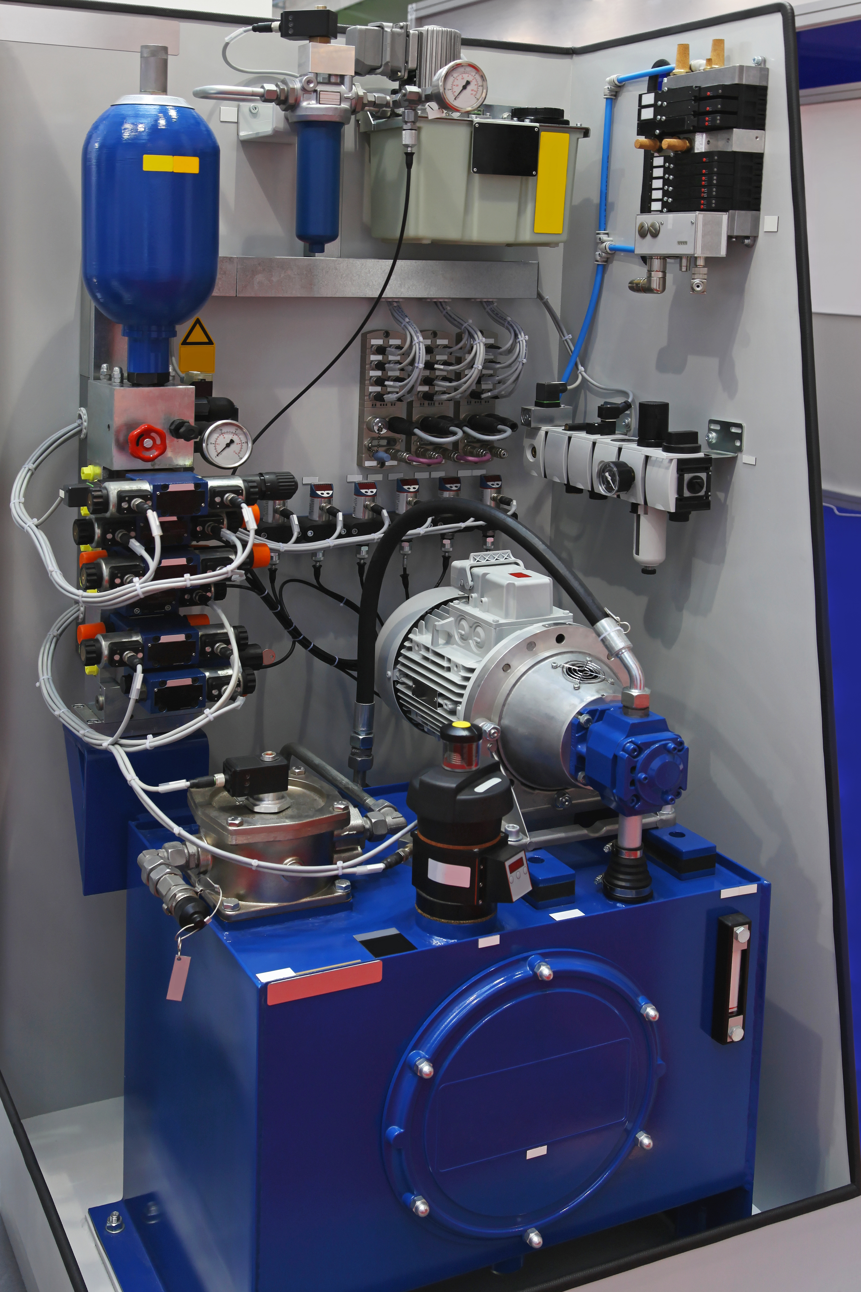
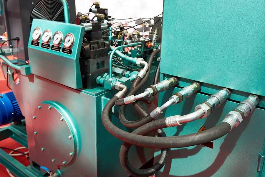
"Pascal"s Law" applies to confined liquids. Thus, in order for liquids to act hydraulically, they must be contained within a system. A hydraulic power pack or hydraulic power unit is a confined mechanical system that utilizes liquid hydraulically. Despite the fact that specific operating systems vary, all hydraulic power units share the same basic components. A reservoir, valves, a piping/tubing system, a pump, and actuators are examples of these components. Similarly, despite their versatility and adaptability, these mechanisms work together in related operating processes at the heart of all hydraulic power packs.
The hydraulic reservoir"s function is to hold a volume of liquid, transfer heat from the system, permit solid pollutants to settle, and aid in releasing moisture and air from the liquid.
Mechanical energy is changed to hydraulic energy by the hydraulic pump. This is accomplished through the movement of liquid, which serves as the transmission medium. All hydraulic pumps operate on the same basic principle of dispensing fluid volume against a resistive load or pressure.
Hydraulic valves are utilized to start, stop, and direct liquid flow in a system. Hydraulic valves are made of spools or poppets and can be actuated hydraulically, pneumatically, manually, electrically, or mechanically.
The end result of Pascal"s law is hydraulic actuators. This is the point at which hydraulic energy is transformed back to mechanical energy. This can be accomplished by using a hydraulic cylinder to transform hydraulic energy into linear movement and work or a hydraulic motor to transform hydraulic energy into rotational motion and work. Hydraulic motors and hydraulic cylinders, like hydraulic pumps, have various subtypes, each meant for specific design use.
The essence of hydraulics can be found in a fundamental physical fact: fluids are incompressible. (As a result, fluids more closely resemble solids than compressible gasses) The incompressible essence of fluid allows it to transfer force and speed very efficiently. This fact is summed up by a variant of "Pascal"s Principle," which states that virtually all pressure enforced on any part of a fluid is transferred to every other part of the fluid. This scientific principle states, in other words, that pressure applied to a fluid transmits equally in all directions.
Furthermore, the force transferred through a fluid has the ability to multiply as it moves. In a slightly more abstract sense, because fluids are incompressible, pressurized fluids should keep a consistent pressure just as they move. Pressure is defined mathematically as a force acting per particular area unit (P = F/A). A simplified version of this equation shows that force is the product of area and pressure (F = P x A). Thus, by varying the size or area of various parts inside a hydraulic system, the force acting inside the pump can be adjusted accordingly (to either greater or lesser). The need for pressure to remain constant is what causes force and area to mirror each other (on the basis of either shrinking or growing). A hydraulic system with a piston five times larger than a second piston can demonstrate this force-area relationship. When a force (e.g., 50lbs) is exerted on the smaller piston, it is multiplied by five (e.g., 250 lbs) and transmitted to the larger piston via the hydraulic system.
Hydraulics is built on fluids’ chemical properties and the physical relationship between pressure, area, and force. Overall, hydraulic applications allow human operators to generate and exert immense mechanical force with little to no physical effort. Within hydraulic systems, both oil and water are used to transmit power. The use of oil, on the other hand, is far more common, owing in part to its extremely incompressible nature.
Pressure relief valves prevent excess pressure by regulating the actuators’ output and redirecting liquid back to the reservoir when necessary. Directional control valves are used to change the size and direction of hydraulic fluid flow.
While hydraulic power transmission is remarkably useful in a wide range of professional applications, relying solely on one type of power transmission is generally unwise. On the contrary, the most efficient strategy is to combine a wide range of power transmissions (pneumatic, hydraulic, mechanical, and electrical). As a result, hydraulic systems must be carefully embedded into an overall power transmission strategy for the specific commercial application. It is necessary to invest in locating trustworthy and skilled hydraulic manufacturers/suppliers who can aid in the development and implementation of an overall hydraulic strategy.
The intended use of a hydraulic pump must be considered when selecting a specific type. This is significant because some pumps may only perform one function, whereas others allow for greater flexibility.
The pump"s material composition must also be considered in the application context. The cylinders, pistons, and gears are frequently made of long-lasting materials like aluminum, stainless steel, or steel that can withstand the continuous wear of repeated pumping. The materials must be able to withstand not only the process but also the hydraulic fluids. Composite fluids frequently contain oils, polyalkylene glycols, esters, butanol, and corrosion inhibitors (though water is used in some instances). The operating temperature, flash point, and viscosity of these fluids differ.
In addition to material, manufacturers must compare hydraulic pump operating specifications to make sure that intended utilization does not exceed pump abilities. The many variables in hydraulic pump functionality include maximum operating pressure, continuous operating pressure, horsepower, operating speed, power source, pump weight, and maximum fluid flow. Standard measurements like length, rod extension, and diameter should be compared as well. Because hydraulic pumps are used in lifts, cranes, motors, and other heavy machinery, they must meet strict operating specifications.
It is critical to recall that the overall power generated by any hydraulic drive system is influenced by various inefficiencies that must be considered in order to get the most out of the system. The presence of air bubbles within a hydraulic drive, for example, is known for changing the direction of the energy flow inside the system (since energy is wasted on the way to the actuators on bubble compression). Using a hydraulic drive system requires identifying shortfalls and selecting the best parts to mitigate their effects. A hydraulic pump is the "generator" side of a hydraulic system that initiates the hydraulic procedure (as opposed to the "actuator" side that completes the hydraulic procedure). Regardless of disparities, all hydraulic pumps are responsible for displacing liquid volume and transporting it to the actuator(s) from the reservoir via the tubing system. Some form of internal combustion system typically powers pumps.
While the operation of hydraulic pumps is normally the same, these mechanisms can be split into basic categories. There are two types of hydraulic pumps to consider: gear pumps and piston pumps. Radial and axial piston pumps are types of piston pumps. Axial pumps produce linear motion, whereas radial pumps can produce rotary motion. The gear pump category is further subdivided into external gear pumps and internal gear pumps.
Each type of hydraulic pump, regardless of piston or gear, is either double-action or single-action. Single-action pumps can only pull, push, or lift in one direction, while double-action pumps can pull, push, or lift in multiple directions.
Vane pumps are positive displacement pumps that maintain a constant flow rate under varying pressures. It is a pump that self-primes. It is referred to as a "vane pump" because the effect of the vane pressurizes the liquid.
This pump has a variable number of vanes mounted onto a rotor that rotates within the cavity. These vanes may be variable in length and tensioned to maintain contact with the wall while the pump draws power. The pump also features a pressure relief valve, which prevents pressure rise inside the pump from damaging it.
Internal gear pumps and external gear pumps are the two main types of hydraulic gear pumps. Pumps with external gears have two spur gears, the spurs of which are all externally arranged. Internal gear pumps also feature two spur gears, and the spurs of both gears are internally arranged, with one gear spinning around inside the other.
Both types of gear pumps deliver a consistent amount of liquid with each spinning of the gears. Hydraulic gear pumps are popular due to their versatility, effectiveness, and fairly simple design. Furthermore, because they are obtainable in a variety of configurations, they can be used in a wide range of consumer, industrial, and commercial product contexts.
Hydraulic ram pumps are cyclic machines that use water power, also referred to as hydropower, to transport water to a higher level than its original source. This hydraulic pump type is powered solely by the momentum of moving or falling water.
Ram pumps are a common type of hydraulic pump, especially among other types of hydraulic water pumps. Hydraulic ram pumps are utilized to move the water in the waste management, agricultural, sewage, plumbing, manufacturing, and engineering industries, though only about ten percent of the water utilized to run the pump gets to the planned end point.
Despite this disadvantage, using hydropower instead of an external energy source to power this kind of pump makes it a prominent choice in developing countries where the availability of the fuel and electricity required to energize motorized pumps is limited. The use of hydropower also reduces energy consumption for industrial factories and plants significantly. Having only two moving parts is another advantage of the hydraulic ram, making installation fairly simple in areas with free falling or flowing water. The water amount and the rate at which it falls have an important effect on the pump"s success. It is critical to keep this in mind when choosing a location for a pump and a water source. Length, size, diameter, minimum and maximum flow rates, and speed of operation are all important factors to consider.
Hydraulic water pumps are machines that move water from one location to another. Because water pumps are used in so many different applications, there are numerous hydraulic water pump variations.
Water pumps are useful in a variety of situations. Hydraulic pumps can be used to direct water where it is needed in industry, where water is often an ingredient in an industrial process or product. Water pumps are essential in supplying water to people in homes, particularly in rural residences that are not linked to a large sewage circuit. Water pumps are required in commercial settings to transport water to the upper floors of high rise buildings. Hydraulic water pumps in all of these situations could be powered by fuel, electricity, or even by hand, as is the situation with hydraulic hand pumps.
Water pumps in developed economies are typically automated and powered by electricity. Alternative pumping tools are frequently used in developing economies where dependable and cost effective sources of electricity and fuel are scarce. Hydraulic ram pumps, for example, can deliver water to remote locations without the use of electricity or fuel. These pumps rely solely on a moving stream of water’s force and a properly configured number of valves, tubes, and compression chambers.
Electric hydraulic pumps are hydraulic liquid transmission machines that use electricity to operate. They are frequently used to transfer hydraulic liquid from a reservoir to an actuator, like a hydraulic cylinder. These actuation mechanisms are an essential component of a wide range of hydraulic machinery.
There are several different types of hydraulic pumps, but the defining feature of each type is the use of pressurized fluids to accomplish a job. The natural characteristics of water, for example, are harnessed in the particular instance of hydraulic water pumps to transport water from one location to another. Hydraulic gear pumps and hydraulic piston pumps work in the same way to help actuate the motion of a piston in a mechanical system.
Despite the fact that there are numerous varieties of each of these pump mechanisms, all of them are powered by electricity. In such instances, an electric current flows through the motor, which turns impellers or other devices inside the pump system to create pressure differences; these differential pressure levels enable fluids to flow through the pump. Pump systems of this type can be utilized to direct hydraulic liquid to industrial machines such as commercial equipment like elevators or excavators.
Hydraulic hand pumps are fluid transmission machines that utilize the mechanical force generated by a manually operated actuator. A manually operated actuator could be a lever, a toggle, a handle, or any of a variety of other parts. Hydraulic hand pumps are utilized for hydraulic fluid distribution, water pumping, and various other applications.
Hydraulic hand pumps may be utilized for a variety of tasks, including hydraulic liquid direction to circuits in helicopters and other aircraft, instrument calibration, and piston actuation in hydraulic cylinders. Hydraulic hand pumps of this type use manual power to put hydraulic fluids under pressure. They can be utilized to test the pressure in a variety of devices such as hoses, pipes, valves, sprinklers, and heat exchangers systems. Hand pumps are extraordinarily simple to use.
Each hydraulic hand pump has a lever or other actuation handle linked to the pump that, when pulled and pushed, causes the hydraulic liquid in the pump"s system to be depressurized or pressurized. This action, in the instance of a hydraulic machine, provides power to the devices to which the pump is attached. The actuation of a water pump causes the liquid to be pulled from its source and transferred to another location. Hydraulic hand pumps will remain relevant as long as hydraulics are used in the commerce industry, owing to their simplicity and easy usage.
12V hydraulic pumps are hydraulic power devices that operate on 12 volts DC supplied by a battery or motor. These are specially designed processes that, like all hydraulic pumps, are applied in commercial, industrial, and consumer places to convert kinetic energy into beneficial mechanical energy through pressurized viscous liquids. This converted energy is put to use in a variety of industries.
Hydraulic pumps are commonly used to pull, push, and lift heavy loads in motorized and vehicle machines. Hydraulic water pumps may also be powered by 12V batteries and are used to move water out of or into the desired location. These electric hydraulic pumps are common since they run on small batteries, allowing for ease of portability. Such portability is sometimes required in waste removal systems and vehiclies. In addition to portable and compact models, options include variable amp hour productions, rechargeable battery pumps, and variable weights.
While non rechargeable alkaline 12V hydraulic pumps are used, rechargeable ones are much more common because they enable a continuous flow. More considerations include minimum discharge flow, maximum discharge pressure, discharge size, and inlet size. As 12V batteries are able to pump up to 150 feet from the ground, it is imperative to choose the right pump for a given use.
Air hydraulic pumps are hydraulic power devices that use compressed air to stimulate a pump mechanism, generating useful energy from a pressurized liquid. These devices are also known as pneumatic hydraulic pumps and are applied in a variety of industries to assist in the lifting of heavy loads and transportation of materials with minimal initial force.
Air pumps, like all hydraulic pumps, begin with the same components. The hydraulic liquids, which are typically oil or water-based composites, require the use of a reservoir. The fluid is moved from the storage tank to the hydraulic cylinder via hoses or tubes connected to this reservoir. The hydraulic cylinder houses a piston system and two valves. A hydraulic fluid intake valve allows hydraulic liquid to enter and then traps it by closing. The discharge valve is the point at which the high pressure fluid stream is rele


 8613371530291