
what is a case drain on a hydraulic pump supplier
On most skidsteer and excavator Hydraulic systems, Hydraulic motors and pumps require a case drain line. Sometimes referred to as a third line, the case drain line will relieve any excess pressure and drain it back to your return line, then into the reservoir. Without a properly installed case drain,
that extra pressure could blow a seal or damage your hydraulic line. For higher flow motors or on piston and gear motors, a case drain line is always required. Although, no matter the size of your motor, a case drain is always a good idea as it will relieve the amount of pressure on your shaft seal, helping to prolong its life. A case drain line
Since most machines have a unique style of coupler, BaumaLight does not include a coupler on our case drain line, although they are available. If your skidsteer is not equipped with a case drain, then it can be field installed.

Often in hydraulic systems, hydraulic motors and pumps run case drain hoses. The reason for this is to drain excess internal oil leakage from the motor. This is certainly critical in a piston motor and pump as the pistons have some internal leakage as they are actually just metal on metal. If no case drain hose is installed then the result will be, at the least, a blown shaft seal, and at worst, a split or damaged housing.
With gear pumps the leakage drains back into the suction hose internally, so no case drain is required. With gear motors and geroller/geroter motors, the oil can drain into the outlet port, however, that means that the oil pressure in the outlet port must not exceed the pressure rating of the seal. If it does, then a case drain needs to be installed. This will then usually mean you can run motors in series without damaging the motor.
If you require assistance with your hydraulic system, motors, pumps, hoses, seals, case drain, oil, lubricants or anything else for that matter, please give us a call on (03) 5382 0574 or call in and see us at Horsham Hydraulics, 84 GolfCourse
This article is based on a basic circuit with single hydraulic internal gear motor. More complex circuits with multiple motors can have different solutions. Collaborate with your motor supplier for the best results for your particular design.
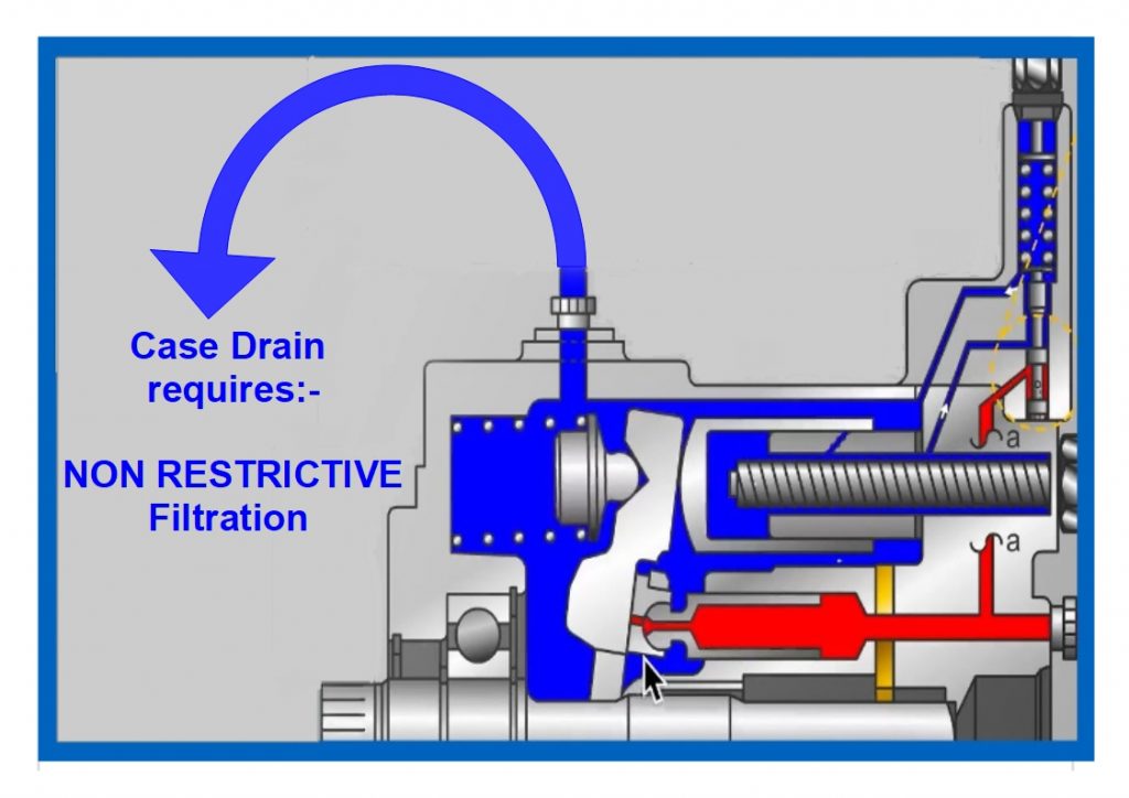
Background: Hydraulic motors have a volumetric efficiency of 90-98%. That means 2 - 10% of the flow entering the motor leaks internally into the case. This is intentional and vital for internal lubrication and clearance between mating pieces.If not allowed to escape, that leakage can build pressure inside the pump case, causing seal leaks or worse, cracks in the cast iron case. The main purpose of a case drain is to allow the internal leakage to escape, but there are other benefits too.
Alternatives: The motor below has a clever solution making the case drain "optional". Two smaller plugs on the rear of this internal gear motor are for check valves.
In the absence of a case drain line, these check valves allow fluid in the case to enter the low-pressure fluid stream. This allows leaked fluid and contamination to exit the motor via the drain line. That might explain why you have seen some hydraulic motors without case drains. However, in a reversing application, that heat and contamination returns to the motor when the direction is reversed.
With a case drain vented to tank, heat and contamination are sent to the reservoir, extending motor life. Even if the case drain port is located on the bottom of the motor, the case will remain filled if the reservoir is above the motor.
A case drain is a specific component of a hydraulic system, its objective is to extend the life of a system and reduce time spent on repairs and maintenance.An unrestricted case-drain line is essential on a piston-type hydraulic motor, whether it has axial, radial or bent-axis design. Most skid steers rely on hydraulic systems to power their front loading arms.
Sometimes referred to as a ‘third line’,a case drain drains back the oil which has leaked past the primary seal, and in doing so, prevents pressure from building up against the outer seal.This oil is then returned to the tank or reservoir.
A case drain will have an in-line case drain filter to prevent contaminants from travelling from the hydraulic motor to the tank. Operating a skid steer without a case drain line could result in a full system failure as the shaft seal will be irreparably blown out, if not installed properly your hydraulic line will not work and in worst cases become damaged beyond repair.
A good case drain makes your hydraulic system more energy efficient and lowers the pressure on the tank, good general maintenance of your hydraulic system results in longer durability for your skid steer and attachments.
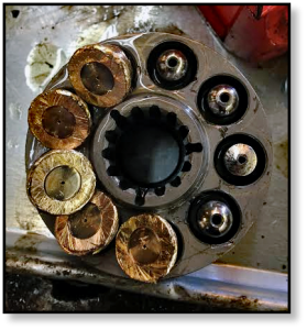
A case drain is made up of multiple elements whose materials vary, it’s important to know how to remove and disassemble the case drain in order to understand its function and materials. A case drain filter is contained within an aluminum canister.
To remove the filter make sure to plug the drain lines to avoid losing hydraulic fluid or introducing contamination into the system. Simply unscrew the hex nut to access the filter element.
You may be surprised to find that case drain filters are made from a metal, sintered bronze to be specific. To the naked eye, the sintered bronze looks like one solid piece of metal but is actually thousands of bronze spheres that have been sintered together. Sintering is a heat treatment, like welding or soldering, that imparts strength and integrity to a ‘powdered’ material.
Sintering can determine a filter’s porosity which affects what goes through the filter and what doesn’t. Once sintered, the filter is now porous enough to allow hydraulic fluid to flow through it, yet remains dense enough to capture contaminants like metal and rubber debris which will eventually lead to a total system failure if left unmaintained.
Filters in a hydraulic system maintain fluid cleanliness at a level that maximizes component life. The appropriate cleanliness level is based on factors such as operating pressure and the internal clearances of components within a system.
If your case drain filter is blocked, then the hydraulic pressure of the motor will increase severely which will eventually lead to a myriad of mechanical and hydraulic issues and even a total system failure. Seals can be blown allowing hydraulic fluid and lubricant to leak out and also allowing contaminants to make their way into the skid steer and damage it irreparably.
If the filter in your case drain is no longer bronze in colour and looks mucky or dirty we suggest that you replace it. If your case drain is blocked then its worth dissembling the other filters and drain on the hydraulic system to ensure they have remained clean. It’s highly discouraged to attempt to clean your case drain or its filter.
Even if you had power tools or a heavy duty wire brush you will only move more trapped solids into the filter, clogging it even further. Case drain replacements are cheap when compared to replacing your whole final drive. Case drain maintenance is a key part of maintaining the life of your skid steer, and is often overlooked.
The main disadvantage of installing a filter on your hydraulics system is that back pressure created by the filter can cause total system failure caused by excessive pressure on the case drain if installed improperly
In some cases, case drains are considered optional. The case drain line is for low volume flow to the tank. In theory, by installing a high-pressure shaft seal and two check valves then internal leakage is technically drained into the return line, which is the usual function of a case line.
It has generally been found that systems without case drains often result in failure due to shaft seal leaks. Case drain line installation can be tedious but will eradicate any problem relating to shaft seal leakage.
Oftentimes, if a vehicle doesn’t already have a case drain line fitted, the manufacturer will not necessarily outline the need for hydraulic fluid to be returned to the tank. If you want optimum reliability from your tank and hydraulics then fitting a case drain line is the way to go.
Case drain lines are a very specific component, its use is debated among hydraulics experts - some say you need a case drain and others suggest you don’t. Ultimately, understanding how a case drain works is fundamental to upholding your machines maintenance and making sure that your tools last for a long time.
Many system failures in hydraulics are caused by leaks from the tank. It’s important not to neglect your hydraulics system as it could put you, or your workers, at risk.
Once you know how case drain filters work and what their function is within the hydraulic system of a skid steer, then you can visit your mechanical professional and ask for their opinion on whether you need to install a case filter on your skid steer or not.

www.powermotiontech.com is using a security service for protection against online attacks. An action has triggered the service and blocked your request.
Please try again in a few minutes. If the issue persist, please contact the site owner for further assistance. Reference ID IP Address Date and Time 8bf2006c85a66667641f5dd58dcb3d35 63.210.148.230 03/07/2023 08:42 AM UTC

The system has three separate circuits, each with an axial-piston pump and a common reservoir. Case drain filtration was included to reduce the possibility of cross-contamination if a failure occured. The pump manufacturer led me to believe that although it isn’t the norm, if the pressure drop across the filter is kept to less than 30 PSI it will be all right. This forces filter maintenance.
Filters in a hydraulic system maintain fluid cleanliness at a level that maximizes component life. The appropriate cleanliness level is based on factors such as operating pressure and the internal clearances of components within a system.
Given that the objective of this process is to extend the service life of components in a system, it is imperative to understand that some filter locations can have the opposite effect.
The rationale for installing filters in piston pump and motor case drain lines is similar to the rationale for locating filtering media in the return line, meaning; if the reservoir and the fluid it contains start out clean and all air entering the reservoir and returning fluid is adequately filtered, fluid cleanliness will be maintained.
The main disadvantage of installing filters on piston pump or motor case drain lines is that the back pressure created by the element can cause failures. Drain line filters can cause excessive case pressure, resulting in seal failure and mechanical damage.
High case pressure results in excessive load on the lip of the shaft seal. This causes the seal lip to wear a groove in the shaft, eventually resulting in leakage past the seal. If case pressure exceeds the shaft seal’s design limits, instantaneous failure can occur. The subsequent loss of oil from the case may result in damage through inadequate lubrication.
The effect of high case pressure on axial piston pumps is similar to excessive vacuum at the pump inlet. Both conditions put the piston-ball and slipper-pad socket in tension during inlet (Figure 1). This causes buckling of the piston retaining plate and/or separation of the slipper from the piston, resulting in catastrophic failure.
High case pressure can cause the pistons of radial piston motors to be lifted off the cam. This occurs in operation during the outlet cycle. The pistons are then hammered back onto the cam during inlet, destroying the motor.
If residual case pressure remains high when the motor is stopped, loss of contact between the pistons and cam allows the motor to freewheel, resulting in uncontrolled machine movement.
I recently witnessed a situation where these problems occurred. I was asked to locate a replacement for a radial piston motor no longer in production. The motor in question was powering a winch on a barge working in an offshore oilfield. The situation was urgent because the downtime was costing the company $40,000 per day. When I inquired about the nature of the failure of the original motor, he reported the following symptoms:
On-site personnel had torn down the motor and sent photos back to the company’s onshore office. The photos of the motor internals showed no obvious failure, confirming my suspicions. I explained that the symptoms described were consistent with high case pressure, most likely as a result of a blocked or restricted case drain line. I later learned that a technician, who had recently completed a contamination control course, connected the motor case drain line back to the tank through the system’s return filter.
To avoid these problems, piston pump and motor case drain lines should be returned to the reservoir through dedicated penetrations. These penetrations must be higher than the unit’s case port and be connected to a drop-pipe inside the reservoir that extends below minimum fluid level.
Due to the reasons above, filters are not recommended on case drain lines. While this does allow a small percentage of fluid to return to the reservoir unfiltered, in most applications the contamination risk is low and can be effectively managed using oil analysis and other condition-based maintenance techniques.
The primary objective of contamination control is extending the service life of hydraulic components. Unfortunately, case drain filters can reduce the service life of piston pumps and motors, making their installation in pursuit of this objective a paradox.
Effective contamination control is achievable using alternative filter locations that do not compromise component reliability. However, if case drain filters are included in a system, precautions must be taken to ensure that damage is not caused to the components they were installed to protect.
If a filter is fitted to a piston pump or motor drain line, I recommend a 125-micron screen, grossly oversized for the maximum expected flow rate to ensure that pressure drop is minimized, even under the most adverse conditions.
The filter housing must incorporate a bypass valve with an opening pressure lower than the maximum allowable case pressure for the particular component (typically 5 to 15 PSIG). Installing a gauge or transducer upstream of the filter for monitoring case pressure is also advisable.
Brendan Casey has more than 20 years experience in the maintenance, repair and overhaul of mobile and industrial equipment. For more information on reducing the operating cost and increasing the...

Sizing case drain lines.Typically, hydraulic motors and pumps have hoses that run to a case drain in order to drain excess internal oil from the motor. Having a case drain usually requires running motors in series to avoid damage. If the case drain line is undersized on a hydraulic pump (piston),it can cause the pressure in the case to be too high. As the pump’s life depreciates, its volumetric efficiency will decrease, which in turn will increase leakage from the case drain line. If there is extreme case pressure, it can cause the piston shoe to lift off of the swash plate. This will cause damage that will force the pump to stop working. Go by the case drain port size or up-size it. It is important to make sure the case pressure is below the max rating, which, if necessary, can be adjusted at the case drain port size, or increase the size of the port. Case pressure can also become too high at:
Alleviate pump failure by mitigating caveated or aerated components.If air is allowed to enter the system, the aeration will produce erosive damage when passing through the pump. In addition, cavitation can cause insufficient pump inlet, which can damage the pump. Either of these conditions can be very destructive.
Aeration is caused by air entering the pump inlet and mixing with the fluid. Low pump pressure at the inlet will cause air bubbles to expand and, as the aerated fluid reaches the pressure side of the pump, the bubbles will disintegrate and implode which causes internal erosion of the system.
Similar to aeration, extreme vacuum in a component will cause cavitation, which allows vapor bubbles to form in the fluid, ultimately damaging the pump.
Either of these conditions will cause pump noise to go up. If the system is allowed to continue to operate the pump will eventually fail. To safeguard against this problem in the design phase any source of air must be contained and the potential of vacuum at the inlet must be alleviated.
If the proper size of the lines is not selected to handle a higher flow rate, unwanted heat will occur causing damage to motors or other hydraulic system components. When designing a hydraulic system valvesmust be selected and sized correctly, or flow will be restricted which can cause it to unseat. In addition, the filter must be sized correctly, or the bypass valve may open causing some of the fluid to be unfiltered or cause a flow surge that could collapse the element.
The control of pressure in a system is paramount in the design. Within hydraulic system components and their functions, pressure control valves are essential in preventing leaks or bursting of pipes, hoses or tubing. This is largely dependent on the proper selection of pressure control valves, which may include:

White House Products Ltd., one of the leading hydraulic gear pump suppliers, is familiar with the importance of monitoring case drain flow and offers some valuable tips for monitoring your hydraulic pump, lines, and overall system performance.
Monitoring the case drain flow in hydraulic piston pumps and motors is beneficial to determine the current state of the hydraulic pump and the status of fluid flow rates. This type of monitoring is considered to be preventative/predictive pump maintenance because you can see the conditions slowly start to degrade over time from continuous pump use. Without maintenance, the pump’s performance and pressure load capability will degrade; excessive wear due to particulate contamination is responsible for the vast majority of all hydraulic component failures.
In the past, it was common to just continue to run piston pumps & motors without any monitoring. Once the fluid degraded and the conditions become too poor to continue to operate the system, the pump was either replaced or rebuilt. Plus, the system was flushed. This often led to long downtimes while the work was being done.
Not to mention, the costs to replace/rebuild a pump and flush the hydraulic system are more expensive than case drain monitoring. Case drain monitoring allows the operator and maintenance technicians to determine the current flow rates and evaluate the pump without having to stop operations.
Once the flow rates start to drop below a percentage of the total expected pump output on the case drain monitor, maintenance technicians will know the pump needs to be serviced, by either rebuilding it or replacing it. Monitoring can also help prevent having to flush the system each time the pump is serviced.
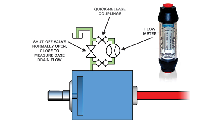
If your case drain flow meter is properly sized, it should be easy to take readings and there should be minimal back pressure on the case of the pump or motor. When selecting a device, determine your application’s flow rate (one method is to calculate 10% of the pump’s total output and picking the closest flow range). When results don’t correspond to a specified range, rounding to the nearest one is helpful.
A case drain monitor can reveal abrupt changes in drain flow and can provide years of service. During installation, check manufacturers’ guidelines for the pump or motor to be certain that the maximum allowable case drain pressure, exceeds the back pressure exerted by the flow monitor. While monitoring pump performance, you can log the baseline flow from the pump case to reservoir and any changes at set time intervals. You’ll instantly know when maintenance or hydraulic pump replacement is required.
Order a hydraulic motor or complete hydraulic pump system from one of the most trusted hydraulic piston pump suppliers. We offer a full range of high-quality hydraulic components so you can have the most reliable hydraulic system possible. Also, find hydraulic diagnostic equipment including flowmeters and pressure gauges to help maximize the reliability of your hydraulic pump installation. For assistance in choosing the right case drain monitors for your hydraulic systems, do not hesitate to call White House Products, Ltd. at +44 (0) 1475 742500 today!

In this Shop Talk Blog post, we are going to discuss the answers to five very common questions about hydraulic motors: what is a case drain, how do hydraulic motors fail, what exactly is displacement, how are hydraulic motors rated, and how does a hydraulic motor differ from a final drive?
Some people may use the terms hydraulic motor and final drive interchangeably, but they aren"t exactly the same. A final drive usually refers to a hydraulic motor that has a speed-reducing
We"ve only covered five of the most common questions about hydraulic motors. If you have any hydraulic motor questions, why not mention them in the comments? We"d love to hear what kind of topics you"d like to have addressed in future blog posts.
is your partner in providing new or remanufactured final drive hydraulic motors from a single mini-excavator to a fleet of heavy equipment. Call today so we can find the right final drive or hydraulic component for you, or check out our online store to.

Mid MichiganWhat is a case drain on a vacuum planter? We are converting our Kinze planter to v-sets. I have a dump valve on the tractor already, will that work for the return on the fan. Thanks
By installing a high-pressure shaft seal and two check valves as shown in the schematic diagram inset above, internal leakage is drained via the return line–something that’s not acceptable for a piston motor or pump!
So the presence of a high pressure shaft seal and check valves renders a dedicated external drain line optional. But not if reliability is the primary concern. Here’s one application example from the ‘coal face’:
“Part of a design modification we carried out to our fleet of drilling rigs required two, low speed, high torque (gerotor) motors being installed on the front of the drilling rig to turn a shaft that housed wire rope brushes to clean the spoil from the drill string. The early design was without case drains because the motors did not require it according to the specification. However after several failed motors due to leaking shaft seals, we installed external case drain lines. It meant quite a bit of extra work and materials (hoses, brackets, fittings etc.) to return the drain back to tank but since then the problem has been eliminated.”
This issue is one of many apparent conflicts in hydraulics between what is OK to do-according to the component manufacturer, and what is best for optimum reliability. Of course, there will always be exceptions to the rule. You may have a gerotor motor without an external drain line that has never leaked and doesn’t look likely to (and this is most probably because the hydraulic system it’s installed on has a low and stable return line pressure).
In other words, not installing a case drain line, even when it’s optional, can turn out to be a costly mistake. And to discover six other costly mistakes you want to be sure to avoid with your hydraulic equipment, get “Six Costly Mistakes Most Hydraulics Users Make… And How You Can Avoid Them!” available for FREE download here.

?I get e-mails like this all the time. I never find time to read them. I decided to read Issue #30 and I couldn"t put it down. I"ll make time from now on.?
?I just love this newsletter. As a Hydraulics Instructor for Eaton, I make copies and distribute them to my students as I address various topics. Please keep "em coming.?

This website is using a security service to protect itself from online attacks. The action you just performed triggered the security solution. There are several actions that could trigger this block including submitting a certain word or phrase, a SQL command or malformed data.

When a pump or motor is worn or damaged, internal leakage increases and therefore the flow available to do useful work decreases. This means that the condition of a pump or motor can be determined by measuring the flow from its case-drain line (internal leakage) and expressing it as a percentage of its theoretical flow. However, using case drain flows to determine the condition of a hydrostatic transmission, without a thorough understanding of closed circuits, can lead to incorrect conclusions and the costly change-out of serviceable components.
A hydrostatic transmission usually comprises a variable-displacement pump and a fixed or variable displacement motor, operating together in a closed circuit. In a closed circuit, fluid from the motor outlet flows directly to the pump inlet, without returning to the tank (Fig. 1).
Because the pump and motor leak internally, which allows fluid to escape from the transmission “loop” and drain back to tank, a fixed-displacement pump called a charge pump is used to ensure that the loop remains full of fluid during normal operation.
In practice, the charge pump not only keeps the loop full of fluid; it pressurizes it to between 110 and 360 psi, depending on the transmission manufacturer. A simple charge pressure circuit comprises the charge pump, a relief valve, and two check valves, through which the charge pump can replenish the transmission loop(Fig. 2).Once the loop is charged to the pressure setting of the charge relief valve, flow from the charge pump passes over the relief valve, through the case of the pump or motor or both, and back to tank.
A variation to this charge circuit arrangement is where the transmission is fitted with a purge valve (also called a transmission valve or replenishing valve or flushing valve). Because the fluid in a closed circuit flows directly from the motor outlet to the pump inlet, it means that apart from losses through internal leakage, the same fluid circulates continuously between pump and motor. If the transmission is heavily loaded, the fluid circulating in the transmission loop can overheat. The function of the purge valve is to positively exchange the fluid in the loop with that in the reservoir.
A purge valve is most effective when it is located at the motor, assuming the charge check valves (Fig. 2) are located in the transmission pump, as is the norm. The effect of this is that cool fluid drawn from the reservoir by the charge pump charges the low-pressure side of the loop through the check valve located close to the transmission pump inlet. The volume of hot fluid leaving the motor outlet that is not required to maintain charge pressure in the low pressure side of the loop vents across the purge valve relief into the case of the motor and back to tank—sometimes via the transmission pump case.
This arrangement is important to keep in mind when using case drain flow to determine the condition of a hydrostatic transmission because charge pump flow must be taken into account.Consider an example where charge pump flow is 10 gpm, of which 4 gpm is leaking out of the loop through the motor’s internals (case drain) and 2 gpm is leaking out of the loop through the pump’s internals. The balance of 4 gpm must therefore be going over either the charge or purge relief valve—but still ends up in the pump or motor case, depending on the location of these valves.
In other words, it is not possible to determine the condition of the component that has the charge or purge relief valve dumping into it because there is no way of telling what proportion of the total case drain flow is due to internal leakage—unless the relief valve can be vented externally while the test is conducted.
When conducting these tests, it is also important to understand that the volume of internal leakage from a hydrostatic transmission cannot exceed the flow rate of its charge pump. Consider for a moment, a transmission that has a volumetric efficiency of 100%, that is, the pump and motor have no internal leakage. The transmission loop has a total volume of two gallons and is full of fluid. Because there is no internal leakage, there is no need for a charge pump.
When the pump is stroked to maximum displacement, this circulates the two gallons of fluid in the loop at a rate of, let’s say, 50 gpm. Because it’s a closed loop, with no leakage, the flow from pump to motor is 50 gpm and the flow from motor to pump is 50 gpm.
Now let’s introduce internal leakage of 0.5 gpm in each of the pump and motor. The result is that, with no charge pump, after one minute there will only be one gallon of fluid left in the loop (the other gallon will have leaked back to tank). However, within a second of the transmission starting to leak, the transmission pump will start to cavitate and the severity of this cavitation will increase with each passing second until the transmission destroys itself.
If a charge pump with a flow rate of 1 gpm is installed in the circuit, the problem is solved, temporarily at least. With 1 gpm leaking out of the loop and 1 gpm being replenished by the charge pump, the status quo is maintained—until wear causes the internal leakage of the transmission pump and/or motor to exceed 1 gpm.
As you can see, it’s not possible for the internal leakage of a hydrostatic transmission to exceed the flow rate of its charge pump. Charge pump flow rate is typically 20% of transmission pump flow rate. This means that volumetric efficiency can drop to 80% before the transmission will start to cavitate and ultimately destroy itself. The trick is to overhaul the transmission before this point is reached!
About the Author:Brendan Casey is the founder of HydraulicSupermarket.com and the author of Insider Secrets to Hydraulics, Preventing Hydraulic Failures, Hydraulics Made Easy and Advanced Hydraulic Control. A fluid power specialist with an MBA, he has more than 20 years experience in the design, maintenance and repair of mobile and industrial hydraulic equipment. Visit his website: www.HydraulicSupermarket.com.

Hydraulic pump and motor users have been faced with an ongoing dilemma… do I install filters on my case drains and risk causing major component damage? …. Or…

PumpMD™ (manufactured by IoT Diagnostics, serviced & distributed by Airline Hydraulics Corp.) provides critical first alerts for your workhorse axial piston pumps. This cost-effective sensor pack allows you to scale across your fleet of pumps and manage schedules around real-time performance data.
Whether you are in the shop, the office, or on the road, never miss a critical alert. Receive instant notifications on pump health (via text, email, and other notifications).
We can configure your PumpMD™ specifications, help place yourorder, or just answer your questions! Connect with an expert by submitting the form below.


 8613371530291