
what is a two stage hydraulic pump factory

2-stage hydraulic pumps are used in motor-driven operations wherein a low-pressure, high rate inlet must be transferred to high pressure, low flow-rate outlet. Single-stage pumps are rated to a static max pressure level and have a limited recycle rate.
To achieve high pressure without a 2-stage unit, the drive engine would require significantly higher horsepower and torque capacity but still lack an effective cycle rate. Other hydraulic pump variants exist – such as piston pumps – but are expensive, making 2-stage units more feasible.
For example, a single gear hydraulic pump might be designed to generate a high-pressure output. Still, it will be unable to repeat a cycle rapidly due to a necessarily low flow rate at the intake. A 2-stage unit ensures consistent flow to increase cycle turnover.
Compactors utilize a similar 2-stage process. High-pressure flow drives the compacting rod, while the low-pressure flow retracts the mechanism and feeds the high-pressure chamber for repeated impacts.
2. Once the first-stage pressure meets a certain pressure threshold, a combiner check valve will open and feed into the second-stage, small-gear unit – joining flows at relatively low pressure.
3. A load sensing pin will trigger the unloading valve to open and the check valve to close. The flow will be directed exclusively to the discharge port.
4. A small amount of fluid may feedback to a load sensing pin to measure the pressure at the outlet and signal lower flow rate in the first unit, lowering the pressure and providing the conditions for a cycle to repeat.
A piston pump operates according to variable displacement. Flow is determined by the angle of an internal slant disk attached to the pump shaft. Pump adjustments – like torque or horsepower limiters – allow piston pumps to emit a max flow rate regardless of pressure level.
In most cases, hydraulic piston pumps are an order of magnitude more expensive than gear-based pumps. Potential downtime and part replacement in high volume work conditions exacerbate price disparities further.
Chiefly: fuel and power consumption. A piston pump operating in high-pressure ranges will regularly demand the full horsepower capabilities of its associated drive engine – increasing the power utilization of the system.
Opportunity cost may also be considered when using a piston pump. Depending on the application (e.g., log splitting), work output can be heavily impacted by the cycle speed of the pump. Not only is a piston pump more expensive to peruse, it is also slower than 2-stage pumps.
Panagon Systems has specialized in manufacturing industry-standard and custom hydraulic assemblies for 25 years. Reach out to our team for a consultation on your specific operational and equipment needs.

A two-stage hydraulic pump is two gear pumps that combine flow at low pressures and only use one pump at high pressures. This allows for high flow rates at low pressures or high pressures at low flow rates. As a result, total horsepower required is limited.
Pumps are rated at their maximum displacement. This is the maximum amount of oil that is produced in a single rotation. This is usually specified in cubic inches per revolution (cipr) or cubic centimeters per revolution (ccpr). Flow is simply the pump displacement multiplied by the rotation speed (usually RPM) and then converted to gallons or liters. For example, a 0.19 cipr pump will produce 1.48 gallons per minute (gpm) at 1800 rpm.
Simply put, gear pumps are positive displacement pumps and are the simplest type you can purchase. Positive displacement means that every time I rotate the shaft there is a fixed amount of oil coming out. In the diagram shown here, oil comes in the bottom and is pressurized by the gears and then moves out the top. The blue gear will spin clockwise. These pumps are small, inexpensive and will handle dirty oil well. As a result, they are the most common pump type on the market.
I found that I was constantly waiting for the cylinder to stroke so that I could insert the next piece. I was really good at determining how much stroke I would need so that wasn’t wasting time over stroking the cylinder.
A piston pump is a variable displacement pump and will produce full flow to no flow depending on a variety of conditions. There is no direct link between shaft rotation and flow output. In the diagram below, there are eight pistons (mini cylinders) arranged in a circle. The movable end is attached to a swashplate which pushes and pulls the pistons in and out of the cylinder. The pistons are all attached to the rotating shaft while the swashplate stays fixed. Oil from the inlet flows into the cylinders as the swashplate is extending the pistons. When the swashplate starts to push the pistons back in, this oil is expelled to the outlet.
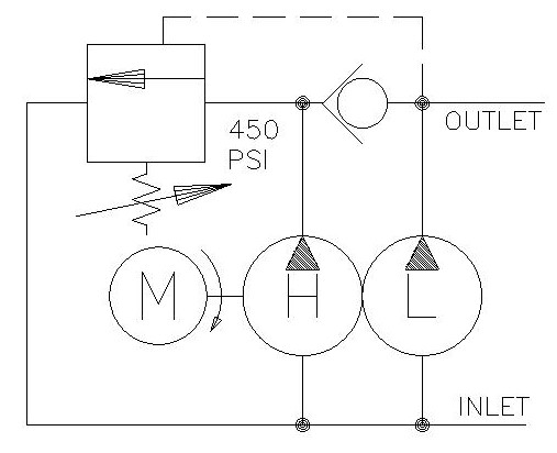
So, we don’t actually turn one of the pumps off. It is very difficult to mechanically disconnect the pump, but we do the next best thing. So earlier in the article I mentioned that pumps move oil they don’t create pressure. Keeping this in mind, we can simply recirculate the oil from the pressure side back to the tank side. Simple. So, let’s look at this as a schematic.
Luckily, turning off the pump is quite simple and only involves two components: a check valve and an unloader valve. The check valve is there to keep the higher-pressure oil from the low flow pump separate from the oil in the high flow pump. The higher-pressure oil from the low flow pump will shift the unloader valve by compressing the spring. This allows flow from the high flow pump to return to the suction line of the pump. Many pumps have this return line internal to the pump, so there is no additional plumbing needed. At this point, the high flow pump uses little to no power to perform this action. You will notice that the cylinder speed slows dramatically. As the log splits apart, the pressure may drop causing the unloader valve to close again. At this point, the flows will combine again. This process may repeat several times during a single split.
The graph above shows the overlay of a performance curve of a piston pump and two stage gear pumps. As you can see, the piston pump between 700 psi and 3000 psi will deliver the maximum HP that our engine can produce and as a result, it will have maximum speed. Unfortunately, it will also have maximum cost. If we are willing to sacrifice a little performance, the two-stage pump will work very well. Most of our work is done under 500 psi where the two pumps have identical performance. As pressure builds, the gear pump will be at a slight disadvantage, but with good performance. The amount of time we spend in this region of the curve is very little and it would be hard to calculate the time wasted.
After the pump on my log splitter died, I replaced it with a two-stage pump. While I was missing out on the full benefits of the piston pump, there was a tremendous increase in my output (logs/hr.). I noticed that instead of me waiting on the cylinder to be in the right position, I was now the hold up. I couldn’t get the logs in and positioned fast enough. What a difference!
As you go from a standard two-stage pump to your own custom design, you will find that you will need to add the check valve and unloader separately. However, there are many available cartridges manifold out there already that make this simple. Some even have relief valves built in!
Two stage pumps are wonderful creations! They allow for better utilization of pressure, flow and power by giving you two performance curve areas. They also show their versatility in conserving power which leads to energy savings while remaining inexpensive. A lot of these pumps come pre-made and preset, but you can make your own! See if your next project can get a boost from one of these wonderful devices.

If you’re looking for information on what is a two stage hydraulic pump, you’ve come to the right place. A two-stage hydraulic pump is a positive displacement pump that uses two pistons to move fluid through a chamber. The first piston, called the “suction” piston, draws fluid into the chamber from the inlet port. The second piston, called the “discharge” piston, pushes fluid out of the chamber through the outlet port.
The suction piston is the first piston in a two-stage hydraulic pump. It is responsible for drawing fluid into the chamber from the inlet port. The suction piston typically has a larger diameter than the discharge piston and may also have a different number of slots or windows cut into it.
The discharge piston is the second piston in atwo-stage hydraulic pump. It is responsible for pushing fluid out of the chamber through the outlet port. The discharge piston typically has a smaller diameter than the suction piston and may also have a different number of slots or windows cut into it.
Two-stage hydraulic pumps are often used when high pressure is required, such as in construction equipment or heavy machinery. They are also sometimes used in automotive applications, such as power steering or brakes. Depending on the application, two-stage hydraulic pumps can either air or water-cooled.
Two-stage hydraulic pumps offer some benefits over other types of positive displacement pumps. They can generate higher pressures than single-stage pumps, making them ideal for use in applications where high pressure is required. Two-stage hydraulic pumps are also more efficient than single-stage pumps, which can move more fluid per cycle while using less energy.
Additionally, two-stage hydraulic pumps are less likely to cavitate than single-stage pumps, making them less likely to damage the pump or cause disruptions in fluid flow.
A two-stage hydraulic pump is a device that uses two pistons to move fluid through a cylinder. The first piston, the low-pressure stage, draws the fluid from the reservoir and moves it into the second stage. The second piston, called the high-pressure stage, forces the fluid through the outlet port at high pressure.
Two-stage hydraulic pumps are used in various applications requiring high volume and pressure. For example, they are commonly used in construction equipment, agricultural machinery, and manufacturing machinery.
Gear pumps and vane pumps. Gear pumps are the most common type of two-stage hydraulic pump. They use gears to move fluid through the pump and are typically used in applications where high pressures are required. Vane pumps use vanes to move fluid through the pump and are typically used in applications with high volumes.
Gear pumps typically have a pressure rating of 3000 psi or more. They are also very efficient, with some models achieving efficiencies as high as 99%.
Always check the pressure relief valve to make sure it is functioning correctly. The pressure relief valve protects the pump from damage if the pressure gets too high.
If the pump is not working correctly, check the inlet and outlet ports to ensure they are clear. Sometimes debris can build up in these ports and block fluid flow.
One-stage hydraulic pumps are less efficient than 2 stage hydraulic pumps. Additionally, 1-stage hydraulic pumps are more likely to cavitate than 2-stage hydraulic pumps, making them less reliable. 2-stage hydraulic pumps are more expensive than 1-stage ones, but they offer superior performance and reliability.
One-stage hydraulic pumps are less efficient than 2 stage hydraulic pumps. This is because they have to pump the fluid twice to reach the high pressure required for most applications.
2 stage hydraulic pumps are more expensive than 1 stage hydraulic pumps. Still, they offer superior performance and reliability. 2 stage hydraulic pumps are more efficient than 1 stage hydraulic pumps because they only have to pump the fluid once. Additionally, 2-stage hydraulic pumps are less likely to cavitate than 1-stage hydraulic pumps, making them more reliable.
Gear pumps and vane pumps. Gear pumps are the most common type of two-stage hydraulic pump. They use gears to move fluid through the pump and are typically used in applications where high pressures are required. Vane pumps use vanes to move fluid through the pump and are typically used in applications with high volumes.
Always check the oil level in the pump before starting it. The pump will not work correctly if the oil level is too low. Always check the pressure relief valve to make sure it is functioning correctly. The pressure relief valve protects the pump from damage if the pressure gets too high. If the pump is not working correctly, check the inlet and outlet ports to ensure they are clear. Sometimes debris can build up in these ports and block fluid flow. If the pump is still not working correctly, check the piston seals. These seals can wear out over time and need to be replaced. Always consult the owner’s manual for your specific model of the two-stage hydraulic pump before performing any maintenance or repairs. By following these tips, you can help ensure that your two-stage hydraulic pump will work correctly and last many years. We hope this guide has helped teach you what is a two-stage hydraulic pump.
• The Economy pump is best suited to power small to medium size fixtures. Its lightweight and compact design makes it ideal for applications which require easy transport of the pump. ...
The axial piston pump generates a maximum working pressure of 700 bar with an oil flow of 0,61 per minute. Tne pump is equipped with a low pressure stage ...
The HP245 range of high flow, two speed, manually operated pumps is ideally suited for applications where high tonnage cylinders are to be used on sites, without any available electric ...
... ready for immediate use. The HP227FP pump incorporates the same specification and features of the HP227FPC pump however is supplied without the pressure gauge, gauge mounting block and 3 metre hose assembly.
Compact, Portable, Cordless Hydraulic Pump for MRO Applications. Compact, Li-ion 18VDC, 9.0 Ah battery-powered pump provides extended run-time. Two-stage, ...
This two-stage, continuous pressure (demand) pump contains all the necessary controls and circuitry for powering single- or double-acting continuous pressure workholding systems. It has ...
This electric/hydraulic pump is a two-stage, continuous pressure (demand) pump that contains all the necessary controls and circuitry for powering any ...
... The Marzocchi 1HL, 1PHL and 2HL High/Low hydraulic gear pumps are special double stage pumps with special integrated valves as shown in the hydraulic ...
Hand or foot pumps – Nominal pressure: 700 bars. Overload valve operating pressure: 720 bars.Dual-stage (two-speed) pumps fitted in their standard versions with a coupler ...
The radial piston pump type R consists of valve-controlled pump elements arranged in star form around an eccentric. For large flow rates, up to 42 pump elements can be set up in 6 stars ...
With DirectIndustry you can: Find the product, subcontractor or service provider you need | Find a nearby distributor or reseller| Contact the manufacturer to get a quote or a price | Examine product characteristics and technical specifications for major brands | View PDF catalogues and other online documentation

This 2-Stage pump fits a wide variety of log splitters and outdoor power equipment and works in both horizontal and vertical orientations. The inlet (suction) port is 1" NPT and the minimum suction hose inner diameter (ID) is 1-1/4". The inlet barbed fitting is not included but is available separately. Use a 1-1/4 ID Suction Hose and 3/4" ID high-pressure hose.
Be sure to use AW-32 10-Weight (ISO 32) or AW-46 20-Weight (ISO 46) light hydraulic fluid. This pump is not designed for use with “universal” or "tractor" transmission oil, such as "303". The use of incorrect fluid may damage the pump and void the warranty.
Make sure the hydraulic fluid reservoir is not below the pump to ensure a sufficient flow of fluid to the pump. The hydraulic fluid reservoir should have a capacity of at least 12 gallons to allow sufficient cooling. Suction-side filtration should be no finer than 150 microns. The use of a 10-25 micron filter on the suction side of the pump is too restrictive and will cause failure.
We recommend using an L-style jaw coupling to connect the pump to an engine. Couplings and mounting brackets are available. You should use at least a 15hp engine to maintain 3,600 RPM under load.

This 2-Stage pump fits a wide variety of log splitters and outdoor power equipment and works in both horizontal and vertical orientations. The included inlet nipple requires a 1" inner diameter suction hose.
Rated for up to 3,000 PSI at 3,600 RPM, this pump can power log splitters from 5 to 35 tons, depending on the inner diameter of the hydraulic cylinder. It features a fast cycle time by moving quickly when unloaded. It automatically shifts to low-flow/high-pressure mode at 500 PSI.
Be sure to use AW-32 10-Weight (ISO 32) or AW-46 20-Weight (ISO 46) light hydraulic fluid or Dexron III automatic transmission fluid. This pump is not designed for use with “universal” or "tractor" transmission oil, such as "303". The use of incorrect fluid may damage the pump and void the warranty.
Make sure the hydraulic fluid reservoir is not below the pump to ensure a sufficient flow of fluid to the pump. Suction-side filtration should be no finer than 150 microns. The use of a 10-25 micron filter on the suction side of the pump is too restrictive and will cause failure.
We recommend using an L-style jaw coupling to connect the pump to an engine. Couplings and mounting brackets are available. You should use at least a 5hp 163cc engine to maintain 3,600 RPM under load.

How does a 2 stage hydraulic pump work? Knowing the answer to this question means going back to the basics. This includes understanding that 2 stage pumps are usually called log splitter pumps. In terms of purpose, these pumps are an amazing way to expect better performance without worrying about an increase in the horsepower.
A 2 stage pump is often regarded as an excellent time-saver. This is because the pump is composed of two pumping parts, along with an inside pressure-sensing valve which works by cutting between the two. A section of the hydraulic pump creates the max gpm flow rate at a relatively low-pressure rate.
As mentioned, looking inside the housing of this type of pump will introduce you to two components – a huge volume pump, alongside its low volume counterpart.
What makes this pump unique is that it makes possible that a hydraulic system produces either high pressure or high flow, which can easily be powered using an engine of a moderate size. The usual log splitters come between 5 and 12 hp.
In contrast to single stage pump which is composed of a single dual suction impeller that is situated on both vehicle sides and giving volume to all of the vehicle discharges, the2-stage hydraulic pump features two suction impellers that work side-by-side.
With this in mind, it is the operator’s call whether more volume or more pressure is required. This can be done by choosing the right switch that is located on the panel of the pump.
In a standard log splitter, a log is placed by the operator on the splitter, shifting a directional valve so as to route fluid coming from the pump and into the cap end of the cylinder. Then, the smaller pump works by moving the piston rod at a low speed, and can still attain higher pressure in pushing the wedge to the log, splitting it.
Engine– The engine is typically a small 4-stroke gasoline engine. It works by providing power to the entire system. It is connected to the hydraulic oil pump. A regular log splitter has a 5-hp gasoline engine or a a higher horsepower such as a Briggs & Stratton engine.
Hydraulic Oil Pump – This component produces a continuous high-pressure oil stream, running to a valve. The usual splitter features a 2 stage hydraulic oil pump that is rated at a max of 11 gpm, at 2500 psi.
Valve – This part allows the operator to actuate the hydraulic cylinder, thus splitting a log. The valves work by applying forward and backward pressure into the piston. A certain type of valve is called “spool valve” because it looks similar to a spool of thread.
Tank – The tank is the component that holds the hydraulic oil which feeds the pump. There is also a filter that keeps the oil clean. It can also be found in the tank. A usual log splitter comes with a 3.5 gallon hydraulic oil tank.
It is also possible to speed up the log splitter. For this, you need to have a bigger hydraulic pump. As you also upgrade your pump, you may also have to upgrade the size of the tank. This will help in preventing fluid overheating. You may also want to increase the size of the hoses, as this will also help in accommodating the increase in the flow rate.
As such, controlling the flow rate of a pump requires setting the output pressure towards the point using the P-V diagram, allowing the pump to provide the flow rate desired.
2 stage hydraulic pumps are often seen in hydraulic systems. They work by allowing the passage of different substances right into the pump, as well as the other components that are in the system. The different aspects of working can be adjusted, such as the valve accuracy, pressure settings, and creating minor adjustments using tools that you can find at home.
Locate the adjustment screw that is situated at the back of the hydraulic gauge. For this process, you can use a flathead screwdriver in turning the screw. This step enables you to easily adjust the needle of the screw. When needed, you can also turn it into zero.
This time, take time in adjusting the pressure switch. This switch can be found at the back of the hydraulic gauge. The best tool for this step is a wrench, using it to loosen the nut on the switch. Turn the adjusting screw afterwards. The pressure switch may also be adjusted in stopping the pump as it reaches a given setting in the pressure. Turn it in a counterclockwise direction to decrease the setting for the pressure switch.
After adjusting the 2 stage hydraulic pump, you can then focus your attention on adjusting the pressure regulating valve. This valve is situated right beside the pressure switch. This can be done with a wrench, loosening the nut on the switch.
Afterward, turn the screw in a clockwise motion to increase the setting for the pressure. Note that the switch needs to be adjusted to make sure that you can achieve a pressure differential of around 300 psi.
How does a 2 stage hydraulic pump work? As mentioned earlier, this equipment is truly a life saver and very effective. It contains two sections for pumping, along with an internal pressure-sensing valve, cutting over between both. A section creates the maximum gallon per minute flow rate at a low pressure. Among the uses include drawing the piston back from a log after splitting the log. Drawing it back to the cylinder requires little force, and should be done fast, so as to expect the best possible flow rate at a lower pressure.
Because these cookies are strictly necessary to deliver the website, refusing them will have impact how our site functions. You always can block or delete cookies by changing your browser settings and force blocking all cookies on this website. But this will always prompt you to accept/refuse cookies when revisiting our site.
We fully respect if you want to refuse cookies but to avoid asking you again and again kindly allow us to store a cookie for that. You are free to opt out any time or opt in for other cookies to get a better experience. If you refuse cookies we will remove all set cookies in our domain.
We provide you with a list of stored cookies on your computer in our domain so you can check what we stored. Due to security reasons we are not able to show or modify cookies from other domains. You can check these in your browser security settings.
Check to enable permanent hiding of message bar and refuse all cookies if you do not opt in. We need 2 cookies to store this setting. Otherwise you will be prompted again when opening a new browser window or new a tab.

Northern Hydraulics offers a full line of 2-stage hydraulic pumps for your log splitters, compactors, and press-type applications. Haldex/Concentric pumps have a cast iron gear housing and are available in flows ranging from 9 GPM to 28 GPM. These 2-stage hydraulic pumps are designed for heavy-duty use and long cycle times. The Haldex brand assures you are getting top-quality, high-performing products. Northern Hydraulics replacement pumps also have a cast iron gear housing and are available in flows ranging from 5 GPM to 28 GPM. These log splitter hydraulic pumps are ideal for the recreational wood splitter user, as they are still a quality product, but offered at a much lower price point.

Hydraulic pumps come in a wide range of styles and designs, and Flowfit Hydraulic two stage hi-lo gear pumps are amongst the most efficient available. These models can give you much faster cycle times and provide a higher maximum pressure, whilst only utilising a small engine. Typically, two-stage hi-lo gear pumps are excellent for use on log-splitters and hydraulic press applications.
Running at 85% efficiency, our range of hydraulic pumps are amongst the most effective in compactly designed hydraulic components available in the UK. With various designs, all available with a range of GPM specifications, you will be able to find the ideal model for your systems requirements amongst our extensive range.

Concentric AB-HILO PUMPS-US-2011-7 2 2 PERFORMANCE CURVES at 3600 RPM, with 300SSU Oil quality products for mechanical & fluid power ~ jbj Techniques Limited, www.jbj.co.uk UK distributor for Concentric Hydraulics
Concentric AB-HILO PUMPS-US-2011-7 3 * At 3600 RPM. ** SAE ports available, consult factory. : Ports and valves on opposite side of casting. 3 As viewed from the shaft end. n These two pumps have square keys, 1/8" x 1", instead of #404 Woodruff Key. 6 Indicates a 1" inlet tube is used. © Indicates 1/2" NPTF port. DIMENSIONAL DRAWINGS GC Series Pictures on front cover are used with the kind permission of eg: Atlet, BT, Huddig, Scania, Toro and Volvo Construction Equipment. 1300483 1300484 1300485 1300356 1300357 1300159 1300486 1300487 5 7 9 11 11 11 13 16 CW CW CW CW CCW CW CW CW Rotation P/N Nominal Flow GPM Shaft Dia. Ext. 1/2 1/2 1/2 1/2 1/2 1/2 1/2 1/2 1.5" 1.5" 1.5" 1.5" 1.5" 1.5" 1.5" 1.5" Mount Type 4-bolt 4-bolt 4-bolt 4-bolt 4-bolt 4-bolt 4-bolt 4-bolt 1/2" NPTF 1/2" NPTF 1/2" NPTF 1/2" NPTF 1/2" NPTF 1" tube 1" tube 1" tube Inlet Outlet 1/2" NPTF 1/2" NPTF 1/2" NPTF 1/2" NPTF 1/2" NPTF 1/2" NPTF 1/2" NPTF 1/2" NPTF Ports Dimensions (inches) A 4.91 4.91 4.91 4.91 4.91 4.91 5.47 5.47 B 4.03 4.03 4.03 4.03 4.03 4.03 4.59 4.59 C 2.53 2.53 2.53 2.53 2.53 2.53 3.09 3.09 GC Series ** * © © © © © 6 6 6 3 : n n A B C 1.25 .125 1.50 .62 .55 .5000 .4997 1.7815 1.7800 # 404 WOODRUFF KEY INLET: SEE TABLE BELOW OPPOSITE: 1/2-14 NPTF OUTLET PORT 2.560 1.780 1.780 2.144 1.000 1.000 1.000 1.000 1.41 2.812 1.41 2.812 .344 DIA. THRU MOUNTING HOLES (4) © © 3.00 INLET TUBE OPTION DIA. DIA. o quality products for mechanical & fluid power ~ jbj Techniques Limited, www.jbj.co.uk UK distributor for Concentric Hydraulics
Concentric AB-HILO PUMPS-US-2011-7 4 DIMENSIONAL DRAWINGS D Series 6.56 1-11 1/2 INLET PORT SHOWN 3/4-14 NPTF OUTLET PORT OPPOSITE SIDE 5.46 3.28 1.50 .2450 .1875 SQ. X 1.00 LONG KEY 3.250 3.248 .6250 .6247 3.61 2.63 .63 .438 DIA. THRU (2) 4.188 2.094 DIA. DIA. 1300488 1300489 22 28 CW CW Rotation P/N Nominal Flow GPM Shaft Dia. Ext. 5/8 5/8 1.5" 1.5" Mount Type SAE A SAE A 1" NPTF 1" NPTF Inlet Outlet 3/4" NPTF 3/4" NPTF Ports D Series * At 3600 RPM. ** SAE ports available, consult factory. As viewed from the shaft end. * ** 3 3 quality products for mechanical & fluid power ~ jbj Techniques Limited, www.jbj.co.uk UK distributor for Concentric Hydraulics
Concentric AB-HILO PUMPS-US-2011-7 5 TWO STAGE HIGH/LOW HYDRAULIC GEAR PUMPS 1300483 1300484 1300485 1300356 1300357 1300159 1300486 1300487 1300488 1300489 5 7 9 11 11 11 13 16 22 28 .065 .065 .194 .194 .194 .194 .194 .258 .465 .465 High Pressure Gear Displ. in.3 P/N Nominal Flow GPM Low Pressure Gear Displ. in.3 .258 .388 .388 .517 .517 .517 .647 .776 .930 1.395 Pump Selection Guide * At 3600 RPM. All pumps factory preset at 650 PSI; for settings outside range, contact factory. NOTE: All pumps above are 3000 PSI max. working pressure, 400-900 PSI unload adjustable range, and 500-4000 RPM range. * Hydraulic Schematic quality products for mechanical & fluid power ~ jbj Techniques Limited, www.jbj.co.uk UK distributor for Concentric Hydraulics
Cast Iron Pumps Heavy Duty GC Series Pumps Displacements 1.06 to 11.65 cc GC Series High/Low Pumps High Pressure Displacements 1.06 to 4.22 cc Low Pressure Displacements 4.22 to 12.71 cc Maximum Pressure 276 bar Maximum Speed 4,000 rpm W-Series Pumps W100 Displacements 0.50 to 2.00 cc W300 Displacements 0.80 to 5.70 cc W600 Displacements 4 to 12 cc W900 Displacements 5 to 31 cc W1200 Displacements 25 to 33 cc W1500 Displacements 19 to 50 cc Maximum Pressure 276 bar Maximum Speed 500 to 4,000 rpm D Series Pumps Displacements 03.80 to 22.85 cc D Series High/Low Pumps High Pressure Displacements 7.62 cc Low Pressure Displacements 15.24 to 22.86 cc Maximum Pressure 207–276 bar Maximum Speed 3,600–4,000 rpm WK900 CALMA Pumps Displacements 5 to 27 cc Maximum Pressure 230 bar Maximum Speed 4,000 rpm F12 & F15 Ferra Series Pumps F12 Displacements 16 – 41 cc F15 Displacements 19 to 50 cc Maximum Pressure 276 bar Maximum Speed 3,600 rpm Cast Iron Displacements 1.06 to 161 cc Speed Up to 10,000 rpm Aluminum Displacements 4 to 50 cc Speed Up to 4,000 rpm Flow Dividers Fluid Motors GC & D Series GC Displacements 1.58 to 8.47 cc D Displacements 3.8 to 13.32 cc Maximum Pressure 310 bar Maximum Input Flow Per Section 14 gpm (53 lpm) Aluminum Pumps Medium/Light Duty F20/F30 Pumps & F20-LS/F30-LS Load Sense Ferra Series Pumps Displacements 23 to 161 cc Maximum Pressure 276 bar Maximum Speed 3,600 rpm PUMPS & MOTORS
PUMP/MOTORS (DC/AC) DC Voltage Range 12 to 72 VDC AC Horsepower Range 0.367749 to 2.2065 kW Pump Displacements 0.65 to 28 cc Maximum Pressure 4276 bar HE “BOX” POWER PACKS Voltage Range 12 to 24 VDC Pump Displacements 0.80 to 6.36 cc Maximum Pressure 230 bar Reservoirs HB800 POWER PACKS Voltage Range 12 to 24 VDC Pump Displacements 0.60 to 1.5 cc Reservoirs 0.5 to 3.8 litres plastic Maximum Pressure 180 bar BIROTATIONAL POWER PACKS Voltage Range 12 to 24 VDC, 115 to 230 VAC Pump Displacements 0.80 to 2.11 cc Reservoirs 1.9 to 2.8 litres plastic, 3.8 to 7.6 litres steel HE1000 SERIES POWER PACKS Voltage Range 12 to 24 VDC Pump Displacements 0.24 to 2 cc Maximum Pressure 230 bar Reservoirs 0.5 to 3.8 litresplastic AC POWER PACKS GC-9500 SERIES Displacements 1.06 to 22.85 cc Maximum Pressure 207 bar Maximum Speed 3,600 rpm Reservoirs 19 to 76 litres steel HE2000 SERIES POWER PACKS Voltage Range 12 to 24 VDC, 115 to 230 VAC Pump Displacements 0.80 to 6.36 cc Maximum Pressure 230 bar Reservoirs 0.9 to 15 litres steel, 0.76 to 1.6 litresplastic 32.84 to 19 litres steel HE-Q (QUIET) POWER PACKS Voltage Range 24 VDC WQ300 Pump Displacements 1.2 to 5.7 cc Noise 42dB(A) Only Concentric offers this extensive range of products worldwide. POWER PACKS
Getting the most out of your machinery often depends on close integration between all components. An organisation that manufactures and integrates all the diverse components of a drivetrain provides the experience to help you select the best component combination for your application. jbj Techniques’ in-house design team and manufacturing facility provide tailored solutions for your applications at competitive prices with quick delivery. The following examples are a simplistic view of how jbj Techniques assists customers. Hydraulic Adaptors Designed primarily to allow the close coupling of hydraulic pumps to a variety of prime movers, such as diesel / petrol engines, electric, air or hydraulic motors, they can also be used in the connection from prime mover to alternative driven parts i.e. gear boxes, generators, water or vacuum pumps etc. An additional range of engine front PTO adaptors, which provide additional connection between the engine pulley and the driven part are also available. The kit comprises of a and flexible bellhousing drive that are fully machined to suit the coupling driving and driven components. These can be to suit either shaft to shaft, flange (flywheel) to shaft or even flange to flange connections. Getting the most out of your equipment will demand close integration between all components. In specifying jbj Techniques as your preferred supplier, you will have selected a company with the experience to specify, manufacture and integrate all of the diverse components that will ensure the best component combination for your application. jbj"s in house design team and manufacturing facility provide tailored solutions for your applications at competitive pricing and on-time deliveries. Pump shaft alignment is key to preventing unnecessary wear and damage to the pump shaft seal and bearing. Improper alignment may lead to premature pump failure. Also to be considered are unwanted torsional resonant frequencies in the system which can quickly cause damage to components in the drivetrain and reduce system life and performance. Improper pump installation can lead to premature failure, increased maintenance costs and reduced production levels of final product. jbj Techniques can advise on the correct installation of into Industrial / hydraulic pumps mobile / marine / machine tool / agricultural / offshore industries and can specify complete driveline systems from their extensive range of components which are available from stock or manufactured to order, albeit simple or complex, standard or bespoke. Electric Motor – Hydraulic Pump Adaptors (safe area) jbj Techniques Limited offer the most comprehensive range of in Europe. bellhousings Designed to connect electric motors with frame size IEC D56 - D400 (0.06kW – 750kW) and can be compatible with electric motor "B5" or "B14" flange configurations. Accompanying the metric frame units above is a complete range of mountings to suit Nema and imperial frame motors with "C" face or "D" flange fitments. With fully machined , torsionally flexible couplings or available, jbj ensure torsionally rigid couplings the most suitable combination is selected for the application in hand. As an example spider couplings are available in various materials including aluminium, grey cast iron, nodular iron, steel and stainless steels and can be finish machined with parallel, taper or splined bores to DIN, SAE, ANSI or ISO standards. Bellhousings can be manufactured in aluminium or cast iron material as standard, however, units can be produced in a variety of exotic materials on request. The aluminium product range is produced in either monoblock or composite formats giving great flexibility in design and allows for early delivery time, often with same or next day delivery possibilities. For applications where low noise levels are a quality products for mechanical & fluid power #DriveLineHarmony www.jbj.co.uk an excellence in engineering
ensuring a continuing high quality service in which customers can have complete confidence. “ “ requirement then a complete range of antivibration and noise reduction components add to the range. Electric motor – Hydraulic Pump Adaptors (hazardous area) Designed to meet the exacting safety standards of the offshore and chemical process industries, jbj Techniques produce certificated to adaptor kits Directive 2014/34/EU II2GD-IM2-TX -50 C< Service Temp < +105 C. Harmonised standards BS EN 1127:1, BS EN 13463:1, BS EN13463:5, BS EN 50303, BS EN 1834-1,BS EN 1834-3. Generally manufactured in Cast or Nodular iron, bellhousings can be produced in steel, stainless steel or alternative exotic materials on customer request. Couplings supplied for these applications are the jbj Techniques "JXL" pin and bush range which provide an anti-static and flameproof drive which meet zone 1 area requirements, conforming to all of the above standards. Also available are spider and gear couplings which are certified to zone 2 standards. (Contact jbj Techniques for details). An important development of equipment for use within hazardous areas is the wet mount series of bellhousings. Commissioned to research and develop a product that would control the high temperature generated by a piston pump shaft seal when working within cycling applications. A little considered issue is the frictional heat generated at the shaft seal when the application requires the pump to cycle between different pressures causing the seal temperature to increase. This process will often take the seal temperature out and above the levels required by the relevant ATEX standards requirement. This specially designed assembly allows a pumped cooling flow to be passed over the seal face and through an auxiliary cooler, this in turn reduces the seal face temperature which can be maintained at an acceptable level. With a vast array of components to select from, jbj are well placed to provide all required components to support the required cooling system. Diesel Engine – Hydraulic Pump Adaptors A complete range of bellhousing and couplings exist for the connection of a diesel engine flywheel to a specified driven component, be it an oil hydraulic pump, water pump, generator or similar device. With the bellhousing available in various materials to suit all application areas. With a standard range to connect Diesel engines with SAE dimensions from SAE "6" to SAE "0" jbj are well placed to satisfy the majority of customer requirements. Couplings to complete the assembly are available in either torsionally flexible or torsionally rigid design ad can be supplied to suit SAE flywheel dimensions from SAE 6.5” to SAE 18”. For hydraulic pumps to be mounted to engines that do not conform to SAE dimensions, we offer a full range of assembly parts, some of which (but not all) are shown here » for diesel engines All bellhousings within this range can be finished machined to accept any, piston, vane or gear pump interfaces requested by customer. As with the electric motor range of product jbj offer complete solutions for ATEX environments, using our well proven "JXL" coupling range which has standard design to connect to the engine flywheel. Directive 2014/34/EU II2GD-IM2-TX -50°C ≤ Service Temp ≤ +105°C. Harmonised Standards: BS EN 1127:1 BS EN 13463:1 BS EN 13463:5 BS EN 50303. Petrol Engine – Hydraulic Pump Adaptors Petrol engine adaptors have been developed for use with industrial petrol engines. Design exists to suit Honda, Briggs and Stratton, Kawasaki, Kubota, Hatz, Mag, Robin, Suzuki, Winsconsin, to name but a few, all adaptors can be finished to accept most hydraulic pumps. Adaptors to suit engine crankshaft drives and for vertical mounting are available on request. #DriveLineHarmony www.jbj.co.ukl to Large Combinations Small Individual Components
to Large Combinations from Small Individual Components ensuring a continuing high quality service in which customers can have complete confidence. “ “ # Driveline jbj Techniques is a specialist supplier of high-quality products for the mechanical power transmission and fluid power sectors. The company offers a high level of in-house expertise plus a huge selection of products to meet a very broad range of customer applications. From specification, through technical advice and manufacture to after-sales support, jbj Techniques provides a comprehensive and valued service to the power transmission and hydraulics industries. The company fields a UK-wide team of technical sales engineers to ensure that the business is close to its customers, and it enjoys excellent associations with European manufacturers, acting as sole UK distributor in many cases. jbj’s team is recognised for its expertise in the selection and configuration of hydraulic and mechanical transmission systems. Able to draw on an that extensive product range provides the building blocks for bespoke systems both large and small, the in-house design team offers a complete service, ranging from an assessment of customer requirements to full technical backup, including product specification, CAD based system design, system build and certification. Moreover customers can take advantage of jbj’s own machine-shop facilities and skilled engineers guarantee to quality and control costs. jbj Techniques provides one of the widest ranges of couplings available within the UK; mechanical power transmission couplings for a vast range of applications. Ranging from miniature couplings, all steel gear couplings, flexible spider couplings, shaft couplings, torque limiting couplings, disc and grid type couplings, ATEX compliant and shaft locking devices. Magnetic couplings for power transmission between hermetically sealed areas. However as extensive as the selection is, couplings make up a fraction of jbj’s portfolio. As power transmission specialists the company stock and provide gearboxes, clutches, pumps, hydraulic motors, flow meters, fluid power accessories including: cooling & heat exchange products, reservoirs, pipe flanges, seals and level indicators, as well as a variety of bellhousings and engine adaptors, to name just a few of the product categories. jbj Techniques Limited is proud of it’s relationship and reputation with customers and suppliers. The core client base is stable and loyal, which is testament to the quality of service provided by the company. A similar relationship exists with suppliers, ensuring a continuing high quality service in which customers can have complete confidence. Dampers Engine Adaptor Kits Hydraulic Adaptors Torque Limiting Couplings Tyre Couplings Anti-static/Flameproof Couplings Torsionally Rigid Couplings Torsionally Flexible Couplings Bellhousings Permanent Magnetic Couplings Torsional Couplings
ne Harmony comprehensive range of components www.jbj.co.uk an excellence in engineering 01737 767493 info@jbj.co.uk www.jbj.co.uk - registered in England No: 1185469 - jbj Techniques Limited is ISO certificated, committed to international coordination & unification of industrial standards. A range of products ATEX certificated to directive 94/9/E requirements Screw Pumps Pneumatic Motors & Starters Gear Pumps/Motors Axial & Radial Piston Motors Vane Pumps LSHT Motors/Geared Motors Splitter Gearboxes Planetary Gearboxes BDS Clutches BD Clutches & Gearboxes Oil Bath Clutches Flow Dividers Tanks/Accessories Fluid Level Indicators Flanges Mini Power Packs Coolers Pressure Intensifiers You Tube
uk distributor for quality products for mechanical & fluid power jbj Techniques Limited www.jbj.co.uk 28 Trowers Way, Holmethorpe Industrial Estate Redhill, Surrey RH1 2LW UNITED KINGDOM tel: 01737 767493 fax: 01737 772041 email: info@jbj.co.uk Concentric will not accept responsibility for any catalogue errors and reserves the right to modify its products without prior notice. This also applies to products already ordered, provided that such modifications can be made without affecting technical specifications. All trademarks in this material are properties of their respective owners. Concentric is an innovator in flow control and fluid power, supplying proprietary systems and components for trucks, buses and industrial vehicles, worldwide. With 1,156 employees and yearly sales exceeding 1,977 million Swedish Kronor, Concentric AB is listed on the Stockholm Stock Exchange (www.concentricAB.com).


 8613371530291