
what is a two stage hydraulic pump free sample
A two-stage hydraulic pump is two gear pumps that combine flow at low pressures and only use one pump at high pressures. This allows for high flow rates at low pressures or high pressures at low flow rates. As a result, total horsepower required is limited.
Pumps are rated at their maximum displacement. This is the maximum amount of oil that is produced in a single rotation. This is usually specified in cubic inches per revolution (cipr) or cubic centimeters per revolution (ccpr). Flow is simply the pump displacement multiplied by the rotation speed (usually RPM) and then converted to gallons or liters. For example, a 0.19 cipr pump will produce 1.48 gallons per minute (gpm) at 1800 rpm.
Simply put, gear pumps are positive displacement pumps and are the simplest type you can purchase. Positive displacement means that every time I rotate the shaft there is a fixed amount of oil coming out. In the diagram shown here, oil comes in the bottom and is pressurized by the gears and then moves out the top. The blue gear will spin clockwise. These pumps are small, inexpensive and will handle dirty oil well. As a result, they are the most common pump type on the market.
I found that I was constantly waiting for the cylinder to stroke so that I could insert the next piece. I was really good at determining how much stroke I would need so that wasn’t wasting time over stroking the cylinder.
A piston pump is a variable displacement pump and will produce full flow to no flow depending on a variety of conditions. There is no direct link between shaft rotation and flow output. In the diagram below, there are eight pistons (mini cylinders) arranged in a circle. The movable end is attached to a swashplate which pushes and pulls the pistons in and out of the cylinder. The pistons are all attached to the rotating shaft while the swashplate stays fixed. Oil from the inlet flows into the cylinders as the swashplate is extending the pistons. When the swashplate starts to push the pistons back in, this oil is expelled to the outlet.
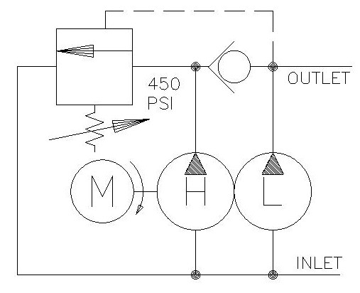
So, we don’t actually turn one of the pumps off. It is very difficult to mechanically disconnect the pump, but we do the next best thing. So earlier in the article I mentioned that pumps move oil they don’t create pressure. Keeping this in mind, we can simply recirculate the oil from the pressure side back to the tank side. Simple. So, let’s look at this as a schematic.
Luckily, turning off the pump is quite simple and only involves two components: a check valve and an unloader valve. The check valve is there to keep the higher-pressure oil from the low flow pump separate from the oil in the high flow pump. The higher-pressure oil from the low flow pump will shift the unloader valve by compressing the spring. This allows flow from the high flow pump to return to the suction line of the pump. Many pumps have this return line internal to the pump, so there is no additional plumbing needed. At this point, the high flow pump uses little to no power to perform this action. You will notice that the cylinder speed slows dramatically. As the log splits apart, the pressure may drop causing the unloader valve to close again. At this point, the flows will combine again. This process may repeat several times during a single split.
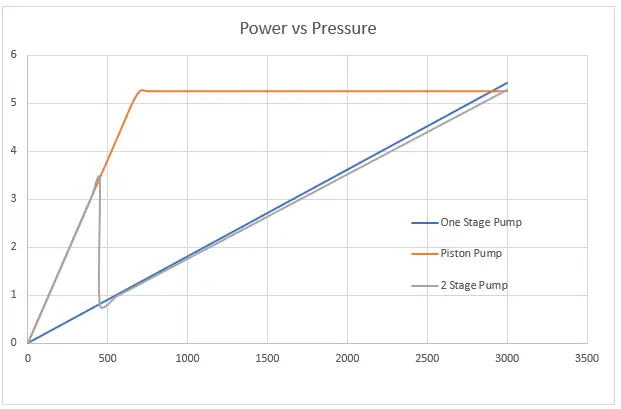
The graph above shows the overlay of a performance curve of a piston pump and two stage gear pumps. As you can see, the piston pump between 700 psi and 3000 psi will deliver the maximum HP that our engine can produce and as a result, it will have maximum speed. Unfortunately, it will also have maximum cost. If we are willing to sacrifice a little performance, the two-stage pump will work very well. Most of our work is done under 500 psi where the two pumps have identical performance. As pressure builds, the gear pump will be at a slight disadvantage, but with good performance. The amount of time we spend in this region of the curve is very little and it would be hard to calculate the time wasted.
After the pump on my log splitter died, I replaced it with a two-stage pump. While I was missing out on the full benefits of the piston pump, there was a tremendous increase in my output (logs/hr.). I noticed that instead of me waiting on the cylinder to be in the right position, I was now the hold up. I couldn’t get the logs in and positioned fast enough. What a difference!
As you go from a standard two-stage pump to your own custom design, you will find that you will need to add the check valve and unloader separately. However, there are many available cartridges manifold out there already that make this simple. Some even have relief valves built in!
Two stage pumps are wonderful creations! They allow for better utilization of pressure, flow and power by giving you two performance curve areas. They also show their versatility in conserving power which leads to energy savings while remaining inexpensive. A lot of these pumps come pre-made and preset, but you can make your own! See if your next project can get a boost from one of these wonderful devices.

2-stage hydraulic pumps are used in motor-driven operations wherein a low-pressure, high rate inlet must be transferred to high pressure, low flow-rate outlet. Single-stage pumps are rated to a static max pressure level and have a limited recycle rate.
To achieve high pressure without a 2-stage unit, the drive engine would require significantly higher horsepower and torque capacity but still lack an effective cycle rate. Other hydraulic pump variants exist – such as piston pumps – but are expensive, making 2-stage units more feasible.
For example, a single gear hydraulic pump might be designed to generate a high-pressure output. Still, it will be unable to repeat a cycle rapidly due to a necessarily low flow rate at the intake. A 2-stage unit ensures consistent flow to increase cycle turnover.
Compactors utilize a similar 2-stage process. High-pressure flow drives the compacting rod, while the low-pressure flow retracts the mechanism and feeds the high-pressure chamber for repeated impacts.
2. Once the first-stage pressure meets a certain pressure threshold, a combiner check valve will open and feed into the second-stage, small-gear unit – joining flows at relatively low pressure.
3. A load sensing pin will trigger the unloading valve to open and the check valve to close. The flow will be directed exclusively to the discharge port.
4. A small amount of fluid may feedback to a load sensing pin to measure the pressure at the outlet and signal lower flow rate in the first unit, lowering the pressure and providing the conditions for a cycle to repeat.
A piston pump operates according to variable displacement. Flow is determined by the angle of an internal slant disk attached to the pump shaft. Pump adjustments – like torque or horsepower limiters – allow piston pumps to emit a max flow rate regardless of pressure level.
In most cases, hydraulic piston pumps are an order of magnitude more expensive than gear-based pumps. Potential downtime and part replacement in high volume work conditions exacerbate price disparities further.
Chiefly: fuel and power consumption. A piston pump operating in high-pressure ranges will regularly demand the full horsepower capabilities of its associated drive engine – increasing the power utilization of the system.
Opportunity cost may also be considered when using a piston pump. Depending on the application (e.g., log splitting), work output can be heavily impacted by the cycle speed of the pump. Not only is a piston pump more expensive to peruse, it is also slower than 2-stage pumps.
Panagon Systems has specialized in manufacturing industry-standard and custom hydraulic assemblies for 25 years. Reach out to our team for a consultation on your specific operational and equipment needs.

www.powermotiontech.com is using a security service for protection against online attacks. An action has triggered the service and blocked your request.
Please try again in a few minutes. If the issue persist, please contact the site owner for further assistance. Reference ID IP Address Date and Time 8bf2006c85a66667641f5dd58dcb3d35 63.210.148.230 03/07/2023 05:29 AM UTC

Hydraulic pumps are mechanisms in hydraulic systems that move hydraulic fluid from point to point initiating the production of hydraulic power. Hydraulic pumps are sometimes incorrectly referred to as “hydrolic” pumps.
They are an important device overall in the hydraulics field, a special kind of power transmission which controls the energy which moving fluids transmit while under pressure and change into mechanical energy. Other kinds of pumps utilized to transmit hydraulic fluids could also be referred to as hydraulic pumps. There is a wide range of contexts in which hydraulic systems are applied, hence they are very important in many commercial, industrial, and consumer utilities.
“Power transmission” alludes to the complete procedure of technologically changing energy into a beneficial form for practical applications. Mechanical power, electrical power, and fluid power are the three major branches that make up the power transmission field. Fluid power covers the usage of moving gas and moving fluids for the transmission of power. Hydraulics are then considered as a sub category of fluid power that focuses on fluid use in opposition to gas use. The other fluid power field is known as pneumatics and it’s focused on the storage and release of energy with compressed gas.
"Pascal"s Law" applies to confined liquids. Thus, in order for liquids to act hydraulically, they must be contained within a system. A hydraulic power pack or hydraulic power unit is a confined mechanical system that utilizes liquid hydraulically. Despite the fact that specific operating systems vary, all hydraulic power units share the same basic components. A reservoir, valves, a piping/tubing system, a pump, and actuators are examples of these components. Similarly, despite their versatility and adaptability, these mechanisms work together in related operating processes at the heart of all hydraulic power packs.
The hydraulic reservoir"s function is to hold a volume of liquid, transfer heat from the system, permit solid pollutants to settle, and aid in releasing moisture and air from the liquid.
Mechanical energy is changed to hydraulic energy by the hydraulic pump. This is accomplished through the movement of liquid, which serves as the transmission medium. All hydraulic pumps operate on the same basic principle of dispensing fluid volume against a resistive load or pressure.
Hydraulic valves are utilized to start, stop, and direct liquid flow in a system. Hydraulic valves are made of spools or poppets and can be actuated hydraulically, pneumatically, manually, electrically, or mechanically.
The end result of Pascal"s law is hydraulic actuators. This is the point at which hydraulic energy is transformed back to mechanical energy. This can be accomplished by using a hydraulic cylinder to transform hydraulic energy into linear movement and work or a hydraulic motor to transform hydraulic energy into rotational motion and work. Hydraulic motors and hydraulic cylinders, like hydraulic pumps, have various subtypes, each meant for specific design use.
The essence of hydraulics can be found in a fundamental physical fact: fluids are incompressible. (As a result, fluids more closely resemble solids than compressible gasses) The incompressible essence of fluid allows it to transfer force and speed very efficiently. This fact is summed up by a variant of "Pascal"s Principle," which states that virtually all pressure enforced on any part of a fluid is transferred to every other part of the fluid. This scientific principle states, in other words, that pressure applied to a fluid transmits equally in all directions.
Furthermore, the force transferred through a fluid has the ability to multiply as it moves. In a slightly more abstract sense, because fluids are incompressible, pressurized fluids should keep a consistent pressure just as they move. Pressure is defined mathematically as a force acting per particular area unit (P = F/A). A simplified version of this equation shows that force is the product of area and pressure (F = P x A). Thus, by varying the size or area of various parts inside a hydraulic system, the force acting inside the pump can be adjusted accordingly (to either greater or lesser). The need for pressure to remain constant is what causes force and area to mirror each other (on the basis of either shrinking or growing). A hydraulic system with a piston five times larger than a second piston can demonstrate this force-area relationship. When a force (e.g., 50lbs) is exerted on the smaller piston, it is multiplied by five (e.g., 250 lbs) and transmitted to the larger piston via the hydraulic system.
Hydraulics is built on fluids’ chemical properties and the physical relationship between pressure, area, and force. Overall, hydraulic applications allow human operators to generate and exert immense mechanical force with little to no physical effort. Within hydraulic systems, both oil and water are used to transmit power. The use of oil, on the other hand, is far more common, owing in part to its extremely incompressible nature.
Pressure relief valves prevent excess pressure by regulating the actuators’ output and redirecting liquid back to the reservoir when necessary. Directional control valves are used to change the size and direction of hydraulic fluid flow.
While hydraulic power transmission is remarkably useful in a wide range of professional applications, relying solely on one type of power transmission is generally unwise. On the contrary, the most efficient strategy is to combine a wide range of power transmissions (pneumatic, hydraulic, mechanical, and electrical). As a result, hydraulic systems must be carefully embedded into an overall power transmission strategy for the specific commercial application. It is necessary to invest in locating trustworthy and skilled hydraulic manufacturers/suppliers who can aid in the development and implementation of an overall hydraulic strategy.
The intended use of a hydraulic pump must be considered when selecting a specific type. This is significant because some pumps may only perform one function, whereas others allow for greater flexibility.
The pump"s material composition must also be considered in the application context. The cylinders, pistons, and gears are frequently made of long-lasting materials like aluminum, stainless steel, or steel that can withstand the continuous wear of repeated pumping. The materials must be able to withstand not only the process but also the hydraulic fluids. Composite fluids frequently contain oils, polyalkylene glycols, esters, butanol, and corrosion inhibitors (though water is used in some instances). The operating temperature, flash point, and viscosity of these fluids differ.
In addition to material, manufacturers must compare hydraulic pump operating specifications to make sure that intended utilization does not exceed pump abilities. The many variables in hydraulic pump functionality include maximum operating pressure, continuous operating pressure, horsepower, operating speed, power source, pump weight, and maximum fluid flow. Standard measurements like length, rod extension, and diameter should be compared as well. Because hydraulic pumps are used in lifts, cranes, motors, and other heavy machinery, they must meet strict operating specifications.
It is critical to recall that the overall power generated by any hydraulic drive system is influenced by various inefficiencies that must be considered in order to get the most out of the system. The presence of air bubbles within a hydraulic drive, for example, is known for changing the direction of the energy flow inside the system (since energy is wasted on the way to the actuators on bubble compression). Using a hydraulic drive system requires identifying shortfalls and selecting the best parts to mitigate their effects. A hydraulic pump is the "generator" side of a hydraulic system that initiates the hydraulic procedure (as opposed to the "actuator" side that completes the hydraulic procedure). Regardless of disparities, all hydraulic pumps are responsible for displacing liquid volume and transporting it to the actuator(s) from the reservoir via the tubing system. Some form of internal combustion system typically powers pumps.
While the operation of hydraulic pumps is normally the same, these mechanisms can be split into basic categories. There are two types of hydraulic pumps to consider: gear pumps and piston pumps. Radial and axial piston pumps are types of piston pumps. Axial pumps produce linear motion, whereas radial pumps can produce rotary motion. The gear pump category is further subdivided into external gear pumps and internal gear pumps.
Each type of hydraulic pump, regardless of piston or gear, is either double-action or single-action. Single-action pumps can only pull, push, or lift in one direction, while double-action pumps can pull, push, or lift in multiple directions.
Vane pumps are positive displacement pumps that maintain a constant flow rate under varying pressures. It is a pump that self-primes. It is referred to as a "vane pump" because the effect of the vane pressurizes the liquid.
This pump has a variable number of vanes mounted onto a rotor that rotates within the cavity. These vanes may be variable in length and tensioned to maintain contact with the wall while the pump draws power. The pump also features a pressure relief valve, which prevents pressure rise inside the pump from damaging it.
Internal gear pumps and external gear pumps are the two main types of hydraulic gear pumps. Pumps with external gears have two spur gears, the spurs of which are all externally arranged. Internal gear pumps also feature two spur gears, and the spurs of both gears are internally arranged, with one gear spinning around inside the other.
Both types of gear pumps deliver a consistent amount of liquid with each spinning of the gears. Hydraulic gear pumps are popular due to their versatility, effectiveness, and fairly simple design. Furthermore, because they are obtainable in a variety of configurations, they can be used in a wide range of consumer, industrial, and commercial product contexts.
Hydraulic ram pumps are cyclic machines that use water power, also referred to as hydropower, to transport water to a higher level than its original source. This hydraulic pump type is powered solely by the momentum of moving or falling water.
Ram pumps are a common type of hydraulic pump, especially among other types of hydraulic water pumps. Hydraulic ram pumps are utilized to move the water in the waste management, agricultural, sewage, plumbing, manufacturing, and engineering industries, though only about ten percent of the water utilized to run the pump gets to the planned end point.
Despite this disadvantage, using hydropower instead of an external energy source to power this kind of pump makes it a prominent choice in developing countries where the availability of the fuel and electricity required to energize motorized pumps is limited. The use of hydropower also reduces energy consumption for industrial factories and plants significantly. Having only two moving parts is another advantage of the hydraulic ram, making installation fairly simple in areas with free falling or flowing water. The water amount and the rate at which it falls have an important effect on the pump"s success. It is critical to keep this in mind when choosing a location for a pump and a water source. Length, size, diameter, minimum and maximum flow rates, and speed of operation are all important factors to consider.
Hydraulic water pumps are machines that move water from one location to another. Because water pumps are used in so many different applications, there are numerous hydraulic water pump variations.
Water pumps are useful in a variety of situations. Hydraulic pumps can be used to direct water where it is needed in industry, where water is often an ingredient in an industrial process or product. Water pumps are essential in supplying water to people in homes, particularly in rural residences that are not linked to a large sewage circuit. Water pumps are required in commercial settings to transport water to the upper floors of high rise buildings. Hydraulic water pumps in all of these situations could be powered by fuel, electricity, or even by hand, as is the situation with hydraulic hand pumps.
Water pumps in developed economies are typically automated and powered by electricity. Alternative pumping tools are frequently used in developing economies where dependable and cost effective sources of electricity and fuel are scarce. Hydraulic ram pumps, for example, can deliver water to remote locations without the use of electricity or fuel. These pumps rely solely on a moving stream of water’s force and a properly configured number of valves, tubes, and compression chambers.
Electric hydraulic pumps are hydraulic liquid transmission machines that use electricity to operate. They are frequently used to transfer hydraulic liquid from a reservoir to an actuator, like a hydraulic cylinder. These actuation mechanisms are an essential component of a wide range of hydraulic machinery.
There are several different types of hydraulic pumps, but the defining feature of each type is the use of pressurized fluids to accomplish a job. The natural characteristics of water, for example, are harnessed in the particular instance of hydraulic water pumps to transport water from one location to another. Hydraulic gear pumps and hydraulic piston pumps work in the same way to help actuate the motion of a piston in a mechanical system.
Despite the fact that there are numerous varieties of each of these pump mechanisms, all of them are powered by electricity. In such instances, an electric current flows through the motor, which turns impellers or other devices inside the pump system to create pressure differences; these differential pressure levels enable fluids to flow through the pump. Pump systems of this type can be utilized to direct hydraulic liquid to industrial machines such as commercial equipment like elevators or excavators.
Hydraulic hand pumps are fluid transmission machines that utilize the mechanical force generated by a manually operated actuator. A manually operated actuator could be a lever, a toggle, a handle, or any of a variety of other parts. Hydraulic hand pumps are utilized for hydraulic fluid distribution, water pumping, and various other applications.
Hydraulic hand pumps may be utilized for a variety of tasks, including hydraulic liquid direction to circuits in helicopters and other aircraft, instrument calibration, and piston actuation in hydraulic cylinders. Hydraulic hand pumps of this type use manual power to put hydraulic fluids under pressure. They can be utilized to test the pressure in a variety of devices such as hoses, pipes, valves, sprinklers, and heat exchangers systems. Hand pumps are extraordinarily simple to use.
Each hydraulic hand pump has a lever or other actuation handle linked to the pump that, when pulled and pushed, causes the hydraulic liquid in the pump"s system to be depressurized or pressurized. This action, in the instance of a hydraulic machine, provides power to the devices to which the pump is attached. The actuation of a water pump causes the liquid to be pulled from its source and transferred to another location. Hydraulic hand pumps will remain relevant as long as hydraulics are used in the commerce industry, owing to their simplicity and easy usage.
12V hydraulic pumps are hydraulic power devices that operate on 12 volts DC supplied by a battery or motor. These are specially designed processes that, like all hydraulic pumps, are applied in commercial, industrial, and consumer places to convert kinetic energy into beneficial mechanical energy through pressurized viscous liquids. This converted energy is put to use in a variety of industries.
Hydraulic pumps are commonly used to pull, push, and lift heavy loads in motorized and vehicle machines. Hydraulic water pumps may also be powered by 12V batteries and are used to move water out of or into the desired location. These electric hydraulic pumps are common since they run on small batteries, allowing for ease of portability. Such portability is sometimes required in waste removal systems and vehiclies. In addition to portable and compact models, options include variable amp hour productions, rechargeable battery pumps, and variable weights.
While non rechargeable alkaline 12V hydraulic pumps are used, rechargeable ones are much more common because they enable a continuous flow. More considerations include minimum discharge flow, maximum discharge pressure, discharge size, and inlet size. As 12V batteries are able to pump up to 150 feet from the ground, it is imperative to choose the right pump for a given use.
Air hydraulic pumps are hydraulic power devices that use compressed air to stimulate a pump mechanism, generating useful energy from a pressurized liquid. These devices are also known as pneumatic hydraulic pumps and are applied in a variety of industries to assist in the lifting of heavy loads and transportation of materials with minimal initial force.
Air pumps, like all hydraulic pumps, begin with the same components. The hydraulic liquids, which are typically oil or water-based composites, require the use of a reservoir. The fluid is moved from the storage tank to the hydraulic cylinder via hoses or tubes connected to this reservoir. The hydraulic cylinder houses a piston system and two valves. A hydraulic fluid intake valve allows hydraulic liquid to enter and then traps it by closing. The discharge valve is the point at which the high pressure fluid stream is released. Air hydraulic pumps have a linked air cylinder in addition to the hydraulic cylinder enclosing one end of the piston.
The protruding end of the piston is acted upon by a compressed air compressor or air in the cylinder. When the air cylinder is empty, a spring system in the hydraulic cylinder pushes the piston out. This makes a vacuum, which sucks fluid from the reservoir into the hydraulic cylinder. When the air compressor is under pressure, it engages the piston and pushes it deeper into the hydraulic cylinder and compresses the liquids. This pumping action is repeated until the hydraulic cylinder pressure is high enough to forcibly push fluid out through the discharge check valve. In some instances, this is connected to a nozzle and hoses, with the important part being the pressurized stream. Other uses apply the energy of this stream to pull, lift, and push heavy loads.
Hydraulic piston pumps transfer hydraulic liquids through a cylinder using plunger-like equipment to successfully raise the pressure for a machine, enabling it to pull, lift, and push heavy loads. This type of hydraulic pump is the power source for heavy-duty machines like excavators, backhoes, loaders, diggers, and cranes. Piston pumps are used in a variety of industries, including automotive, aeronautics, power generation, military, marine, and manufacturing, to mention a few.
Hydraulic piston pumps are common due to their capability to enhance energy usage productivity. A hydraulic hand pump energized by a hand or foot pedal can convert a force of 4.5 pounds into a load-moving force of 100 pounds. Electric hydraulic pumps can attain pressure reaching 4,000 PSI. Because capacities vary so much, the desired usage pump must be carefully considered. Several other factors must also be considered. Standard and custom configurations of operating speeds, task-specific power sources, pump weights, and maximum fluid flows are widely available. Measurements such as rod extension length, diameter, width, and height should also be considered, particularly when a hydraulic piston pump is to be installed in place of a current hydraulic piston pump.
Hydraulic clutch pumps are mechanisms that include a clutch assembly and a pump that enables the user to apply the necessary pressure to disengage or engage the clutch mechanism. Hydraulic clutches are crafted to either link two shafts and lock them together to rotate at the same speed or detach the shafts and allow them to rotate at different speeds as needed to decelerate or shift gears.
Hydraulic pumps change hydraulic energy to mechanical energy. Hydraulic pumps are particularly designed machines utilized in commercial, industrial, and residential areas to generate useful energy from different viscous liquids pressurization. Hydraulic pumps are exceptionally simple yet effective machines for moving fluids. "Hydraulic" is actually often misspelled as "Hydralic". Hydraulic pumps depend on the energy provided by hydraulic cylinders to power different machines and mechanisms.
There are several different types of hydraulic pumps, and all hydraulic pumps can be split into two primary categories. The first category includes hydraulic pumps that function without the assistance of auxiliary power sources such as electric motors and gas. These hydraulic pump types can use the kinetic energy of a fluid to transfer it from one location to another. These pumps are commonly called ram pumps. Hydraulic hand pumps are never regarded as ram pumps, despite the fact that their operating principles are similar.
The construction, excavation, automotive manufacturing, agriculture, manufacturing, and defense contracting industries are just a few examples of operations that apply hydraulics power in normal, daily procedures. Since hydraulics usage is so prevalent, hydraulic pumps are unsurprisingly used in a wide range of machines and industries. Pumps serve the same basic function in all contexts where hydraulic machinery is used: they transport hydraulic fluid from one location to another in order to generate hydraulic energy and pressure (together with the actuators).
Elevators, automotive brakes, automotive lifts, cranes, airplane flaps, shock absorbers, log splitters, motorboat steering systems, garage jacks and other products use hydraulic pumps. The most common application of hydraulic pumps in construction sites is in big hydraulic machines and different types of "off-highway" equipment such as excavators, dumpers, diggers, and so on. Hydraulic systems are used in other settings, such as offshore work areas and factories, to power heavy machinery, cut and bend material, move heavy equipment, and so on.
Fluid’s incompressible nature in hydraulic systems allows an operator to make and apply mechanical power in an effective and efficient way. Practically all force created in a hydraulic system is applied to the intended target.
Because of the relationship between area, pressure, and force (F = P x A), modifying the force of a hydraulic system is as simple as changing the size of its components.
Hydraulic systems can transfer energy on an equal level with many mechanical and electrical systems while being significantly simpler in general. A hydraulic system, for example, can easily generate linear motion. On the contrary, most electrical and mechanical power systems need an intermediate mechanical step to convert rotational motion to linear motion.
Hydraulic systems are typically smaller than their mechanical and electrical counterparts while producing equivalents amounts of power, providing the benefit of saving physical space.
Hydraulic systems can be used in a wide range of physical settings due to their basic design (a pump attached to actuators via some kind of piping system). Hydraulic systems could also be utilized in environments where electrical systems would be impractical (for example underwater).
By removing electrical safety hazards, using hydraulic systems instead of electrical power transmission improves relative safety (for example explosions, electric shock).
The amount of power that hydraulic pumps can generate is a significant, distinct advantage. In certain cases, a hydraulic pump could generate ten times the power of an electrical counterpart. Some hydraulic pumps (for example, piston pumps) cost more than the ordinary hydraulic component. These drawbacks, however, can be mitigated by the pump"s power and efficiency. Despite their relatively high cost, piston pumps are treasured for their strength and capability to transmit very viscous fluids.
Handling hydraulic liquids is messy, and repairing leaks in a hydraulic pump can be difficult. Hydraulic liquid that leaks in hot areas may catch fire. Hydraulic lines that burst may cause serious injuries. Hydraulic liquids are corrosive as well, though some are less so than others. Hydraulic systems need frequent and intense maintenance. Parts with a high factor of precision are frequently required in systems. If the power is very high and the pipeline cannot handle the power transferred by the liquid, the high pressure received by the liquid may also cause work accidents.
Even though hydraulic systems are less complex than electrical or mechanical systems, they are still complex systems that should be handled with caution. Avoiding physical contact with hydraulic systems is an essential safety precaution when engaging with them. Even when a hydraulic machine is not in use, active liquid pressure within the system can be a hazard.
Inadequate pumps can cause mechanical failure in the place of work that can have serious and costly consequences. Although pump failure has historically been unpredictable, new diagnostic technology continues to improve on detecting methods that previously relied solely on vibration signals. Measuring discharge pressures enables manufacturers to forecast pump wear more accurately. Discharge sensors are simple to integrate into existing systems, increasing the hydraulic pump"s safety and versatility.
Hydraulic pumps are devices in hydraulic systems that move hydraulic fluid from point to point, initiating hydraulic power production. They are an important device overall in the hydraulics field, a special kind of power transmission that controls the energy which moving fluids transmit while under pressure and change into mechanical energy. Hydraulic pumps are divided into two categories namely gear pumps and piston pumps. Radial and axial piston pumps are types of piston pumps. Axial pumps produce linear motion, whereas radial pumps can produce rotary motion. The construction, excavation, automotive manufacturing, agriculture, manufacturing, and defense contracting industries are just a few examples of operations that apply hydraulics power in normal, daily procedures.
A hydraulic pump converts mechanical energy into fluid power. It"s used in hydraulic systems to perform work, such as lifting heavy loads in excavators or jacks to being used in hydraulic splitters. This article focuses on how hydraulic pumps operate, different types of hydraulic pumps, and their applications.
A hydraulic pump operates on positive displacement, where a confined fluid is subjected to pressure using a reciprocating or rotary action. The pump"s driving force is supplied by a prime mover, such as an electric motor, internal combustion engine, human labor (Figure 1), or compressed air (Figure 2), which drives the impeller, gear (Figure 3), or vane to create a flow of fluid within the pump"s housing.
A hydraulic pump’s mechanical action creates a vacuum at the pump’s inlet, which allows atmospheric pressure to force fluid into the pump. The drawn in fluid creates a vacuum at the inlet chamber, which allows the fluid to then be forced towards the outlet at a high pressure.
Vane pump:Vanes are pushed outwards by centrifugal force and pushed back into the rotor as they move past the pump inlet and outlet, generating fluid flow and pressure.
Piston pump:A piston is moved back and forth within a cylinder, creating chambers of varying size that draw in and compress fluid, generating fluid flow and pressure.
A hydraulic pump"s performance is determined by the size and shape of the pump"s internal chambers, the speed at which the pump operates, and the power supplied to the pump. Hydraulic pumps use an incompressible fluid, usually petroleum oil or a food-safe alternative, as the working fluid. The fluid must have lubrication properties and be able to operate at high temperatures. The type of fluid used may depend on safety requirements, such as fire resistance or food preparation.
Air hydraulic pump:These pumps have a compact design and do not require an external power source. However, a reliable source of compressed air is necessary and is limited by the supply pressure of compressed air.
Electric hydraulic pump:They have a reliable and efficient power source and can be easily integrated into existing systems. However, these pumps require a constant power source, may be affected by power outages, and require additional electrical safety measures. Also, they have a higher upfront cost than other pump types.
Gas-powered hydraulic pump:Gas-powered pumps are portable hydraulic pumps which are easy to use in outdoor and remote environments. However, they are limited by fuel supply, have higher emissions compared to other hydraulic pumps, and the fuel systems require regular maintenance.
Manual hydraulic pump:They are easy to transport and do not require a power source. However, they are limited by the operator’s physical ability, have a lower flow rate than other hydraulic pump types, and may require extra time to complete tasks.
Hydraulic hand pump:Hydraulic hand pumps are suitable for small-scale, and low-pressure applications and typically cost less than hydraulic foot pumps.
Hydraulic foot pump:Hydraulic foot pumps are suitable for heavy-duty and high-pressure applications and require less effort than hydraulic hand pumps.
Hydraulic pumps can be single-acting or double-acting. Single-acting pumps have a single port that hydraulic fluid enters to extend the pump’s cylinder. Double-acting pumps have two ports, one for extending the cylinder and one for retracting the cylinder.
Single-acting:With single-acting hydraulic pumps, the cylinder extends when hydraulic fluid enters it. The cylinder will retract with a spring, with gravity, or from the load.
Double-acting:With double-acting hydraulic pumps, the cylinder retracts when hydraulic fluid enters the top port. The cylinder goes back to its starting position.
Single-acting:Single-acting hydraulic pumps are suitable for simple applications that only need linear movement in one direction. For example, such as lifting an object or pressing a load.
Double-acting:Double-acting hydraulic pumps are for applications that need precise linear movement in two directions, such as elevators and forklifts.
Pressure:Hydraulic gear pumps and hydraulic vane pumps are suitable for low-pressure applications, and hydraulic piston pumps are suitable for high-pressure applications.
Cost:Gear pumps are the least expensive to purchase and maintain, whereas piston pumps are the most expensive. Vane pumps land somewhere between the other two in cost.
Efficiency:Gear pumps are the least efficient. They typically have 80% efficiency, meaning 10 mechanical horsepower turns into 8 hydraulic horsepower. Vane pumps are more efficient than gear pumps, and piston pumps are the most efficient with up to 95% efficiency.
Automotive industry:In the automotive industry, hydraulic pumps are combined with jacks and engine hoists for lifting vehicles, platforms, heavy loads, and pulling engines.
Process and manufacturing:Heavy-duty hydraulic pumps are used for driving and tapping applications, turning heavy valves, tightening, and expanding applications.
Despite the different pump mechanism types in hydraulic pumps, they are categorized based on size (pressure output) and driving force (manual, air, electric, and fuel-powered). There are several parameters to consider while selecting the right hydraulic pump for an application. The most important parameters are described below:
Source of driving force: Is it to be manually operated (by hand or foot), air from a compressor, electrical power, or a fuel engine as a prime mover? Other factors that may affect the driving force type are whether it will be remotely operated or not, speed of operation, and load requirement.
Speed of operation: If it is a manual hydraulic pump, should it be a single-speed or double-speed? How much volume of fluid per handle stroke? When using a powered hydraulic pump, how much volume per minute? Air, gas, and electric-powered hydraulic pumps are useful for high-volume flows.
Portability: Manual hand hydraulic pumps are usually portable but with lower output, while fuel power has high-output pressure but stationary for remote operations in places without electricity. Electric hydraulic pumps can be both mobile and stationary, as well as air hydraulic pumps. Air hydraulic pumps require compressed air at the operation site.
Operating temperature: The application operating temperature can affect the size of the oil reservoir needed, the type of fluid, and the materials used for the pump components. The oil is the operating fluid but also serves as a cooling liquid in heavy-duty hydraulic pumps.
Operating noise: Consider if the environment has a noise requirement. A hydraulic pump with a fuel engine will generate a higher noise than an electric hydraulic pump of the same size.
Spark-free: Should the hydraulic pump be spark-free due to a possible explosive environment? Remember, most operating fluids are derivatives of petroleum oil, but there are spark-free options.
A hydraulic pump transforms mechanical energy into fluid energy. A relatively low amount of input power can turn into a large amount of output power for lifting heavy loads.
A hydraulic pump works by using mechanical energy to pressurize fluid in a closed system. This pressurized fluid is then used to drive machinery such as excavators, presses, and lifts.
A hydraulic ram pump leverages the energy of falling water to move water to a higher height without the usage of external power. It is made up of a valve, a pressure chamber, and inlet and exit pipes.
A water pump moves water from one area to another, whereas a hydraulic pump"s purpose is to overcome a pressure that is dependent on a load, like a heavy car.

A gear pump is a type of positive displacement (PD) pump. It moves a fluid by repeatedly enclosing a fixed volume using interlocking cogs or gears, transferring it mechanically using a cyclic pumping action. It delivers a smooth pulse-free flow proportional to the rotational speed of its gears.
Gear pumps use the actions of rotating cogs or gears to transfer fluids. The rotating element develops a liquid seal with the pump casing and creates suction at the pump inlet. Fluid, drawn into the pump, is enclosed within the cavities of its rotating gears and transferred to the discharge. There are two basic designs of gear pump: external and internal(Figure 1).
An external gear pump consists of two identical, interlocking gears supported by separate shafts. Generally, one gear is driven by a motor and this drives the other gear (the idler). In some cases, both shafts may be driven by motors. The shafts are supported by bearings on each side of the casing.
As the gears come out of mesh on the inlet side of the pump, they create an expanded volume. Liquid flows into the cavities and is trapped by the gear teeth as the gears continue to rotate against the pump casing.
No fluid is transferred back through the centre, between the gears, because they are interlocked. Close tolerances between the gears and the casing allow the pump to develop suction at the inlet and prevent fluid from leaking back from the discharge side (although leakage is more likely with low viscosity liquids).
An internal gear pump operates on the same principle but the two interlocking gears are of different sizes with one rotating inside the other. The larger gear (the rotor) is an internal gear i.e. it has the teeth projecting on the inside. Within this is a smaller external gear (the idler –only the rotor is driven) mounted off-centre. This is designed to interlock with the rotor such that the gear teeth engage at one point. A pinion and bushing attached to the pump casing holds the idler in position. A fixed crescent-shaped partition or spacer fills the void created by the off-centre mounting position of the idler and acts as a seal between the inlet and outlet ports.
As the gears come out of mesh on the inlet side of the pump, they create an expanded volume. Liquid flows into the cavities and is trapped by the gear teeth as the gears continue to rotate against the pump casing and partition.
Gear pumps are compact and simple with a limited number of moving parts. They are unable to match the pressure generated by reciprocating pumps or the flow rates of centrifugal pumps but offer higher pressures and throughputs than vane or lobe pumps. Gear pumps are particularly suited for pumping oils and other high viscosity fluids.
Of the two designs, external gear pumps are capable of sustaining higher pressures (up to 3000 psi) and flow rates because of the more rigid shaft support and closer tolerances. Internal gear pumps have better suction capabilities and are suited to high viscosity fluids, although they have a useful operating range from 1cP to over 1,000,000cP. Since output is directly proportional to rotational speed, gear pumps are commonly used for metering and blending operations. Gear pumps can be engineered to handle aggressive liquids. While they are commonly made from cast iron or stainless steel, new alloys and composites allow the pumps to handle corrosive liquids such as sulphuric acid, sodium hypochlorite, ferric chloride and sodium hydroxide.
External gear pumps can also be used in hydraulic power applications, typically in vehicles, lifting machinery and mobile plant equipment. Driving a gear pump in reverse, using oil pumped from elsewhere in a system (normally by a tandem pump in the engine), creates a hydraulic motor. This is particularly useful to provide power in areas where electrical equipment is bulky, costly or inconvenient. Tractors, for example, rely on engine-driven external gear pumps to power their services.
Gear pumps are self-priming and can dry-lift although their priming characteristics improve if the gears are wetted. The gears need to be lubricated by the pumped fluid and should not be run dry for prolonged periods. Some gear pump designs can be run in either direction so the same pump can be used to load and unload a vessel, for example.
The close tolerances between the gears and casing mean that these types of pump are susceptible to wear particularly when used with abrasive fluids or feeds containing entrained solids. However, some designs of gear pumps, particularly internal variants, allow the handling of solids. External gear pumps have four bearings in the pumped medium, and tight tolerances, so are less suited to handling abrasive fluids. Internal gear pumps are more robust having only one bearing (sometimes two) running in the fluid. A gear pump should always have a strainer installed on the suction side to protect it from large, potentially damaging, solids.
Generally, if the pump is expected to handle abrasive solids it is advisable to select a pump with a higher capacity so it can be operated at lower speeds to reduce wear. However, it should be borne in mind that the volumetric efficiency of a gear pump is reduced at lower speeds and flow rates. A gear pump should not be operated too far from its recommended speed.
For high temperature applications, it is important to ensure that the operating temperature range is compatible with the pump specification. Thermal expansion of the casing and gears reduces clearances within a pump and this can also lead to increased wear, and in extreme cases, pump failure.
Despite the best precautions, gear pumps generally succumb to wear of the gears, casing and bearings over time. As clearances increase, there is a gradual reduction in efficiency and increase in flow slip: leakage of the pumped fluid from the discharge back to the suction side. Flow slip is proportional to the cube of the clearance between the cog teeth and casing so, in practice, wear has a small effect until a critical point is reached, from which performance degrades rapidly.
Gear pumps continue to pump against a back pressure and, if subjected to a downstream blockage will continue to pressurise the system until the pump, pipework or other equipment fails. Although most gear pumps are equipped with relief valves for this reason, it is always advisable to fit relief valves elsewhere in the system to protect downstream equipment.
Internal gear pumps, operating at low speed, are generally preferred for shear-sensitive liquids such as foodstuffs, paint and soaps. The higher speeds and lower clearances of external gear designs make them unsuitable for these applications. Internal gear pumps are also preferred when hygiene is important because of their mechanical simplicity and the fact that they are easy to strip down, clean and reassemble.
Gear pumps are commonly used for pumping high viscosity fluids such as oil, paints, resins or foodstuffs. They are preferred in any application where accurate dosing or high pressure output is required. The output of a gear pump is not greatly affected by pressure so they also tend to be preferred in any situation where the supply is irregular.
A gear pump moves a fluid by repeatedly enclosing a fixed volume within interlocking cogs or gears, transferring it mechanically to deliver a smooth pulse-free flow proportional to the rotational speed of its gears. There are two basic types: external and internal. An external gear pump consists of two identical, interlocking gears supported by separate shafts. An internal gear pump has two interlocking gears of different sizes with one rotating inside the other.
Gear pumps are commonly used for pumping high viscosity fluids such as oil, paints, resins or foodstuffs. They are also preferred in applications where accurate dosing or high pressure output is required. External gear pumps are capable of sustaining higher pressures (up to 7500 psi) whereas internal gear pumps have better suction capabilities and are more suited to high viscosity and shear-sensitive fluids.

A gear pump is a type of positive displacement (PD) pump. Gear pumps use the actions of rotating cogs or gears to transfer fluids. The rotating gears develop a liquid seal with the pump casing and create a vacuum at the pump inlet. Fluid, drawn into the pump, is enclosed within the cavities of the rotating gears and transferred to the discharge. A gear pump delivers a smooth pulse-free flow proportional to the rotational speed of its gears.
There are two basic designs of gear pump: internal and external (Figure 1). An internal gear pump has two interlocking gears of different sizes with one rotating inside the other. An external gear pump consists of two identical, interlocking gears supported by separate shafts. Generally, one gear is driven by a motor and this drives the other gear (the idler). In some cases, both shafts may be driven by motors. The shafts are supported by bearings on each side of the casing.
As the gears come out of mesh on the inlet side of the pump, they create an expanded volume. Liquid flows into the cavities and is trapped by the gear teeth as the gears continue to rotate against the pump casing.
No fluid is transferred back through the centre, between the gears, because they are interlocked. Close tolerances between the gears and the casing allow the pump to develop suction at the inlet and prevent fluid from leaking back from the discharge side (although leakage is more likely with low viscosity liquids).
External gear pump designs can utilise spur, helical or herringbone gears (Figure 3). A helical gear design can reduce pump noise and vibration because the teeth engage and disengage gradually throughout the rotation. However, it is important to balance axial forces resulting from the helical gear teeth and this can be achieved by mounting two sets of ‘mirrored’ helical gears together or by using a v-shaped, herringbone pattern. With this design, the axial forces produced by each half of the gear cancel out. Spur gears have the advantage that they can be run at very high speed and are easier to manufacture.
Gear pumps are compact and simple with a limited number of moving parts. They are unable to match the pressure generated by reciprocating pumps or the flow rates of centrifugal pumps but offer higher pressures and throughputs than vane or lobe pumps. External gear pumps are particularly suited for pumping water, polymers, fuels and chemical additives. Small external gear pumps usually operate at up to 3500 rpm and larger models, with helical or herringbone gears, can operate at speeds up to 700 rpm. External gear pumps have close tolerances and shaft support on both sides of the gears. This allows them to run at up to 7250 psi (500 bar), making them well suited for use in hydraulic power applications.
Since output is directly proportional to speed and is a smooth pulse-free flow, external gear pumps are commonly used for metering and blending operations as the metering is continuous and the output is easy to monitor. The low internal volume provides for a reliable measure of liquid passing through a pump and hence accurate flow control. They are also used extensively in engines and gearboxes to circulate lubrication oil. External gear pumps can also be used in hydraulic power applications, typically in vehicles, lifting machinery and mobile plant equipment. Driving a gear pump in reverse, using oil pumped from elsewhere in a system (normally by a tandem pump in the engine), creates a motor. This is particularly useful to provide power in areas where electrical equipment is bulky, costly or inconvenient. Tractors, for example, rely on engine-driven external gear pumps to power their services.
External gear pumps can be engineered to handle aggressive liquids. While they are commonly made from cast iron or stainless steel, new alloys and composites allow the pumps to handle corrosive liquids such as sulphuric acid, sodium hypochlorite, ferric chloride and sodium hydroxide.
External gear pumps are self-priming and can dry-lift although their priming characteristics improve if the gears are wetted. The gears need to be lubricated by the pumped fluid and should not be run dry for prolonged periods. Some gear pump designs can be run in either direction so the same pump can be used to load and unload a vessel, for example.
The close tolerances between the gears and casing mean that these types of pump are susceptible to wear particularly when used with abrasive fluids or feeds containing entrained solids. External gear pumps have four bearings in the pumped medium, and tight tolerances, so are less suited to handling abrasive fluids. For these applications, internal gear pumps are more robust having only one bearing (sometimes two) running in the fluid. A gear pump should always have a strainer installed on the suction side to protect it from large, potentially damaging, solids.
Generally, if the pump is expected to handle abrasive solids it is advisable to select a pump with a higher capacity so it can be operated at lower speeds to reduce wear. However, it should be borne in mind that the volumetric efficiency of a gear pump is reduced at lower speeds and flow rates. A gear pump should not be operated too far from its recommended speed.
For high temperature applications, it is important to ensure that the operating temperature range is compatible with the pump specification. Thermal expansion of the casing and gears reduces clearances within a pump and this can also lead to increased wear, and in extreme cases, pump failure.
Despite the best precautions, gear pumps generally succumb to wear of the gears, casing and bearings over time. As clearances increase, there is a gradual reduction in efficiency and increase in flow slip: leakage of the pumped fluid from the discharge back to the suction side. Flow slip is proportional to the cube of the clearances between the cog teeth and casing so, in practice, wear has a small effect until a critical point is reached, from which performance degrades rapidly.
Gear pumps continue to pump against a back pressure and, if subjected to a downstream blockage will continue to pressurise the system until the pump, pipework or other equipment fails. Although most gear pumps are equipped with relief valves for this reason, it is always advisable to fit relief valves elsewhere in the system to protect downstream equipment.
The high speeds and tight clearances of external gear pumps make them unsuitable for shear-sensitive liquids such as foodstuffs, paint and soaps. Internal gear pumps, operating at lower speed, are generally preferred for these applications.
External gear pumps are commonly used for pumping water, light oils, chemical additives, resins or solvents. They are preferred in any application where accurate dosing is required such as fuels, polymers or chemical additives. The output of a gear pump is not greatly affected by pressure so they also tend to be preferred in any situation where the supply is irregular.
An external gear pump moves a fluid by repeatedly enclosing a fixed volume within interlocking gears, transferring it mechanically to deliver a smooth pulse-free flow proportional to the rotational speed of its gears.
External gear pumps are commonly used for pumping water, light oils, chemical additives, resins or solvents. They are preferred in applications where accurate dosing or high pressure output is required. External gear pumps are capable of sustaining high pressures. The tight tolerances, multiple bearings and high speed operation make them less suited to high viscosity fluids or any abrasive medium or feed with entrained solids.

Check that the electric motor is running. Although this is a simple concept, before you begin replacing parts, it’s critical that you make sure the electric motor is running. This can often be one of the easiest aspects to overlook, but it is necessary to confirm before moving forward.
Check that the pump shaft is rotating. Even though coupling guards and C-face mounts can make this difficult to confirm, it is important to establish if your pump shaft is rotating. If it isn’t, this could be an indication of a more severe issue, and this should be investigated immediately.
Check the oil level. This one tends to be the more obvious check, as it is often one of the only factors inspected before the pump is changed. The oil level should be three inches above the pump suction. Otherwise, a vortex can form in the reservoir, allowing air into the pump.
If the oil level is low, determine where the leak is in the system. Although this can be a difficult process, it is necessary to ensure your machines are performing properly. Leaks can be difficult to find.
What does the pump sound like when it is operating normally? Vane pumps generally are quieter than piston and gear pumps. If the pump has a high-pitched whining sound, it most likely is cavitating. If it has a knocking sound, like marbles rattling around, then aeration is the likely cause.
Cavitation is the formation and collapse of air cavities in the liquid. When the pump cannot get the total volume of oil it needs, cavitation occurs. Hydraulic oil contains approximately nine percent dissolved air. When the pump does not receive adequate oil volume at its suction port, high vacuum pressure occurs.
This dissolved air is pulled out of the oil on the suction side and then collapses or implodes on the pressure side. The implosions produce a very steady, high-pitched sound. As the air bubbles collapse, the inside of the pump is damaged.
While cavitation is a devastating development, with proper preventative maintenance practices and a quality monitoring system, early detection and deterrence remain attainable goals. UE System’s UltraTrak 850S CD pump cavitation sensor is a Smart Analog Sensor designed and optimized to detect cavitation on pumps earlier by measuring the ultrasound produced as cavitation starts to develop early-onset bubbles in the pump. By continuously monitoring the impact caused by cavitation, the system provides a simple, single value to trend and alert when cavitation is occurring.
The oil viscosity is too high. Low oil temperature increases the oil viscosity, making it harder for the oil to reach the pump. Most hydraulic systems should not be started with the oil any colder than 40°F and should not be put under load until the oil is at least 70°F.
Many reservoirs do not have heaters, particularly in the South. Even when heaters are available, they are often disconnected. While the damage may not be immediate, if a pump is continually started up when the oil is too cold, the pump will fail prematurely.
The suction filter or strainer is contaminated. A strainer is typically 74 or 149 microns in size and is used to keep “large” particles out of the pump. The strainer may be located inside or outside the reservoir. Strainers located inside the reservoir are out of sight and out of mind. Many times, maintenance personnel are not even aware that there is a strainer in the reservoir.
The suction strainer should be removed from the line or reservoir and cleaned a minimum of once a year. Years ago, a plant sought out help to troubleshoot a system that had already had five pumps changed within a single week. Upon closer inspection, it was discovered that the breather cap was missing, allowing dirty air to flow directly into the reservoir.
A check of the hydraulic schematic showed a strainer in the suction line inside the tank. When the strainer was removed, a shop rag was found wrapped around the screen mesh. Apparently, someone had used the rag to plug the breather cap opening, and it had then fallen into the tank. Contamination can come from a variety of different sources, so it pays to be vigilant and responsible with our practices and reliability measures.
The electric motor is driving the hydraulic pump at a speed that is higher than the pump’s rating. All pumps have a recommended maximum drive speed. If the speed is too high, a higher volume of oil will be needed at the suction port.
Due to the size of the suction port, adequate oil cannot fill the suction cavity in the pump, resulting in cavitation. Although this rarely happens, some pumps are rated at a maximum drive speed of 1,200 revolutions per minute (RPM), while others have a maximum sp


 8613371530291