
what is cc in hydraulic pump free sample

www.powermotiontech.com is using a security service for protection against online attacks. An action has triggered the service and blocked your request.
Please try again in a few minutes. If the issue persist, please contact the site owner for further assistance. Reference ID IP Address Date and Time 8bf2006c85a66667641f5dd58dcb3d35 63.210.148.230 03/07/2023 05:23 AM UTC
Calculation of preliminary cooler capacity: Heat dissipation from hydraulic oil tanks, valves, pipes and hydraulic components is less than a few percent in standard mobile equipment and the cooler capacity must include some margins. Minimum cooler capacity, Ecooler = 0.25Ediesel
At least 25% of the input power must be dissipated by the cooler when peak power is utilized for long periods. In normal case however, the peak power is used for only short periods, thus the actual cooler capacity required might be considerably less. The oil volume in the hydraulic tank is also acting as a heat accumulator when peak power is used.
The system efficiency is very much dependent on the type of hydraulic work tool equipment, the hydraulic pumps and motors used and power input to the hydraulics may vary considerably. Each circuit must be evaluated and the load cycle estimated. New or modified systems must always be tested in practical work, covering all possible load cycles.
An easy way of measuring the actual average power loss in the system is to equip the machine with a test cooler and measure the oil temperature at the cooler inlet, the oil temperature at the cooler outlet and the oil flow through the cooler, when the machine is in normal operating mode. From these figures the test cooler power dissipation can be calculated and this is equal to the power loss when temperatures are stabilized. From this test the actual required cooler can be calculated to reach specified oil temperature in the oil tank. One problem can be to assemble the measuring equipment in-line, especially the oil flow meter.
Hydraulic pumps are used in hydraulic drive systems and can be hydrostatic or hydrodynamic. A hydraulic pump is a mechanical source of power that converts mechanical power into hydraulic energy (hydrostatic energy i.e. flow, pressure). It generates flow with enough power to overcome pressure induced by the load at the pump outlet. When a hydraulic pump operates, it creates a vacuum at the pump inlet, which forces liquid from the reservoir into the inlet line to the pump and by mechanical action delivers this liquid to the pump outlet and forces it into the hydraulic system.
Hydrostatic pumps are positive displacement pumps while hydrodynamic pumps can be fixed displacement pumps, in which the displacement (flow through the pump per rotation of the pump) cannot be adjusted, or variable displacement pumps, which have a more complicated construction that allows the displacement to be adjusted. Hydrodynamic pumps are more frequent in day-to-day life. Hydrostatic pumps of various types all work on the principle of Pascal"s law.
Gear pumps (with external teeth) (fixed displacement) are simple and economical pumps. The swept volume or displacement of gear pumps for hydraulics will be between about 1 to 200 milliliters. They have the lowest volumetric efficiency (η
A rotary vane pump is a positive-displacement pump that consists of vanes mounted to a rotor that rotates inside a cavity. In some cases these vanes can have variable length and/or be tensioned to maintain contact with the walls as the pump rotates. A critical element in vane pump design is how the vanes are pushed into contact with the pump housing, and how the vane tips are machined at this very point. Several type of "lip" designs are used, and the main objective is to provide a tight seal between the inside of the housing and the vane, and at the same time to minimize wear and metal-to-metal contact. Forcing the vane out of the rotating centre and towards the pump housing is accomplished using spring-loaded vanes, or more traditionally, vanes loaded hydrodynamically (via the pressurized system fluid).
Screw pumps (fixed displacement) consist of two Archimedes" screws that intermesh and are enclosed within the same chamber. These pumps are used for high flows at relatively low pressure (max 100 bars (10,000 kPa)).ball valves
The major problem of screw pumps is that the hydraulic reaction force is transmitted in a direction that"s axially opposed to the direction of the flow.
Bent axis pumps, axial piston pumps and motors using the bent axis principle, fixed or adjustable displacement, exists in two different basic designs. The Thoma-principle (engineer Hans Thoma, Germany, patent 1935) with max 25 degrees angle and the Wahlmark-principle (Gunnar Axel Wahlmark, patent 1960) with spherical-shaped pistons in one piece with the piston rod, piston rings, and maximum 40 degrees between the driveshaft centerline and pistons (Volvo Hydraulics Co.). These have the best efficiency of all pumps. Although in general, the largest displacements are approximately one litre per revolution, if necessary a two-liter swept volume pump can be built. Often variable-displacement pumps are used so that the oil flow can be adjusted carefully. These pumps can in general work with a working pressure of up to 350–420 bars in continuous work.
By using different compensation techniques, the variable displacement type of these pumps can continuously alter fluid discharge per revolution and system pressure based on load requirements, maximum pressure cut-off settings, horsepower/ratio control, and even fully electro proportional systems, requiring no other input than electrical signals. This makes them potentially hugely power saving compared to other constant flow pumps in systems where prime mover/diesel/electric motor rotational speed is constant and required fluid flow is non-constant.
A radial piston pump is a form of hydraulic pump. The working pistons extend in a radial direction symmetrically around the drive shaft, in contrast to the axial piston pump.
When you need to choose a hydraulic pump solution for a hydraulic system, it is important to decide what type of pump you will require. You must also understand the basics of how pumps work and hydraulics.
All hydraulic systems rely on pressurized fluid to create force in order to perform work that is accomplished by transforming mechanical energy into hydraulic energy inside hydraulic pumps and creating a positive displacement downstream. For example, a forklift needs to raise and lower pallets—which would be the desired work.
You must also choose between a ‘closed-loop’ or ‘open-loop’ system. In a ‘closed-loop’ system, the fluid passes from the pump directly to the motor before returning to the pump. In an ‘open-loop’ system, the pump draws the fluid from a reservoir or tank, and then pumps it to a control valve from where it is directed to the services being operated before returning to the tank.
Fixed-displacement pumps are well suited to a wide range of functions where the amount of pressure required to perform work is the same each and every time. For instance, if the pump is rated as a 30 cc pump, it will pump 30 ml of hydraulic fluid through the system for every single rotation.
The pressure and flow rate will not change, no matter how the pump is operated or what occurs elsewhere in the system. If you need a lower flow rate, then you will have to divert the excess flow or use a variable displacement pump.
Two common types of fixed-displacement pumps you can use are the bent axis piston pump and the gear pump. The bent axis piston pump provides the added benefit of normally having a higher pressure capability than a gear pump.
Aside from flow rates being directly proportional to pump drive speeds, fixed-displacement hydraulic pumps have several key benefits over variable displacement pumps, including:
Unlike fixed-displacement pumps, variable displacement pumps are able to increase or decrease the fluid flow rates electronically, manually, or hydraulically. The method used will depend on the flow required and the type of pump being used, such as a vane pump, axial piston pump, etc.
Furthermore, the method of displacement changes based on the pump’s internal structure. For example, a variable displacement piston pump is determined by the bore area of the pistons and the stroke length. The stroke length can vary to help regulate the flow rates as shaft rotation turns and moves the pistons inside the pump.
The control piston inside the pump also helps regular pressure and, essentially, functions as a relief valve. When pressure increases above the desired pressure compensator setting, the control piston moves outwards and slows the travel distance of the other pistons.
As can be seen, fixed-displacement pumps and variable displacement pumps have their own benefits, depending on your specific needs. For further assistance in choosing the right pump or for other hydraulic system solutions, please feel free to contact White House Products, Ltd. at +44 (0) 1475 742500 today!
The ideal in hydraulic system designis to match overall efficiencies to the application performance expectation. This requires the designer to first match the motor, then the pump to a specific system performance expectation. Whether the requirement is to do something within a specific time frame, or in handling a given amount of load, the design of the entire system will change depending on the motor selected.
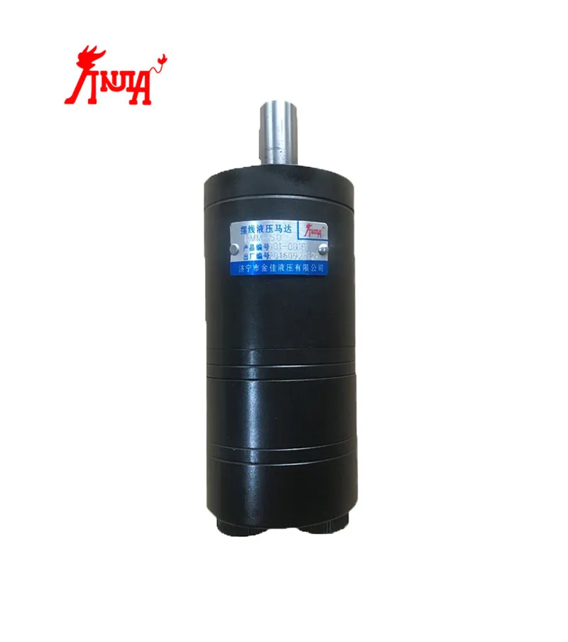
A hydraulic motor is a hydraulic actuator that, when properly connected into a hydraulic system, will produce a rotary actuation. This can be unidirectional or bidirectional depending on the system design. Motors are similar in design to pumps only where a pump takes a rotary actuation to move hydraulic fluid out of the unit, whereas a motor will take flow into itself and put out a rotaryactuation.
The motor selection comes first in the process because application design best practices require that you start with the load requirement, then work back to the prime mover—the pump that will put the fluid power into the motor selected to deliver the performance goal.
Each motor type—gear, vane, in-line piston, bent-axis piston and radial piston—has a specific performance profile. So, knowing the application performance requirement and which motor type best meets the objective is the first step. Then it’s necessary to evaluate the cost of your motor options along with the degree of complexity you want for the overall system.
In the end, it all goes back to the application’s performance expectations. Some have severe duty cycles, while others do not. If, for example, you consider running a low-efficiency, lighter-duty motor into a higher-duty cycle application, the life of the motor will be less than the life of a higher-duty cycle motor that is designed to operate in those types of environments. It is important to understand what operating pressures and flows are required for the motor selected to achieve the application performance expectations.
Each motor type has its own set of applications where they are a better choice than others. For example, if a small gear motor designed to operate at a max of 3,000 psi and 1,000 rpm is put into an application that requires it to run consistently at 3,000 psi and 1,000 rpm, the motor will be running in a “corner” overstressed condition and have a reduced life—even though it is technically within its ratings. The better motor choice would be a motor with higher ratings that will live longer in the application. Granted, there is a greater cost in going with a higher rated motor. The final decision always will depend on what is required in terms of application performance and motor life versus where you want to be with cost.
How motors are ratedMotors are rated bydisplacement, with displacement defined as the volume of fluid that it takes to rotate the shaft of the motor once. The common rating units are cubic inches per revolution (CIR), or cubic centimeters per revolution (CCR).
Motors are also rated bytorque—the amount of twisting force the motor can deliver. The common measurements of torque are inch-pounds (in.-lb) and Newton-meters (Nm). The torque of a motor is a function of motor displacement and system pressure.
Starting torqueis the torque the motor can generate to turn a load when starting from a stop. In general, starting toque is the lowest torque rating of a hydraulic motor due to inefficiencies.
The rotationalspeedof the motor shaft is measured in units of rotations per minute (rpm). Motor speed is a function of hydraulic input flow and motor displacement.
Pressure is generated by resistance to hydraulic flow. The more resistance, the higher the pressure. Common measurement units are pounds per square inch (psi), kilo Pascal’s (kPa) or bar.
Common motor classes and typesGenerally, hydraulic motors are placed into one of two classifications: high speed, low torque (HSLT) or low speed, high torque (LSHT).
Gear motorscome in two varieties—the gerotor/geroller or orbital and external spur gear designs. Orbital styles are classified as LSHT motors; however, some do exist with the HSLT classification. They consist of a matched gear set enclosed in a housing. When hydraulic fluid is moved into the motor, it causes the gears to rotate. One of the gears is connected to the motor output shaft, which produces the motor’s rotary motion. Key features include:
Applications include mobile hydraulics, agricultural machinery to drive conveyor belts, dispersion plates, screw conveyors or fans. Their biggest drawback is that they have a higher noise level.
Vane motorsare typically classified as HSLT units. However, larger displacements will fall into the LSHT range. Hydraulic fluid enters the motor and is applied to a rectangular vane, which slides into and out of the center rotor. This center rotor is connected to the main output shaft. The fluid being applied to the vane causes the output shaft to rotate.
Parker’s vane motors feature a balanced design where the inlet and outlet ports of the motor are applied to sections of the vane cartridge that are 180° apart from each other to ensure that the hydraulic forces are always in balance inside the motor. Key features include:
In-line piston motorsare classified as HSLT. Hydraulic fluid enters the motor and is applied to a series of pistons inside a cylinder barrel. The pistons are pressed against a swash plate, which is at an angle. The pistons push against this angle, which causes the rotation of the swash plate that is mechanically connected to the output shaft of the motor. The swash plate can be a fixed or variable angle. Variable angle motors can have their displacements adjusted between a maximum and minimum setting. The command signals to change the displacement can be electrical, hydraulic or a combination of both.
Bent-axis piston motorsare classified as HSLT. They are similar to inline motors except that the piston barrel is at an angle in relation to the swash plate. Hydraulic fluid enters the motor and is applied to the pistons, which are contained in a cylinder barrel. The pistons are at an angle to the drive shaft, which means that the piston will rotate the shaft as fluid enters the motor.
They can be both fixed and variable displacement. In a variable-displacement bent-axis motor, the cylinder barrel is rotated between maximum and minimum displacements. The command signals to change the displacement can be electrical, hydraulic or a combination of both.
They are best known for high performance, high pressures, high speeds and volumetric mechanical efficiencies in the 97 to 98% range. The also offer quick reaction and precise control. These motors are suitable for applications that require a significant amount of power. They are used to drive mobile and construction equipment, winches, ship-cranes and all kinds of heavy-duty hydraulic equipment for offshore and onshore operations.
Radial piston motorsare LSHT classified. These motors are designed with pistons arranged perpendicular to the output shaft. Typically, the pistons will ride against a cam, which is mechanically connected to the output shaft. The pistons will force the cam to rotate as hydraulic fluid enters the motor.
In general, these motors are fixed displacement. However, some versions will allow for variable displacement. They accomplish this by limiting the number of pistons that can receive hydraulic fluid. Other versions change the internal geometry of the cam the pistons areacting against.
Proper hydraulic motor selection starts with the expected performance required by the application, then works back to the prime mover—the pump. Then it is necessary to evaluate the cost of your motor options along with the degree of complexity you want for the overall system.
Whenever you’re dealing with a hydraulic system you always get asked, “What is your systems pressure and flow rate?” or, “Why is pressure and flow so important?”
For our discussion, let’s talk specifically about fixed displacement components. There are variable displacement pumps and motors used in equipment today but to make these concepts easier to digest I will refer to fixed displacement components. Examples of fixed displacement components are gear pumps, gear motors, and hydraulic cylinders.Pressure and flow are the main variables when working with fluid power systems. Let’s look closer at flow rate.
Fixed displacement hydraulic motors require a fixed volume of oil to cause the shaft to turn 1 revolution. This volume is referred to the motors displacement, usually measured in cubic inch displacement (CID) or cubic centimeter (CC). If you supply the motor with 100 times its CID every minute, it will turn 100 RPM. Speed up the flow rate and motor will go faster, slow it down and the motor will turn slower.
Because of the differences in units of measure (gallons, inches, cubic inches, etc.) we have equations to help with the conversions. For example, a motor with a 3 CID displacement turning @ 1,000 RPM requires 3,000 cubic inches of oil flow every minute (3×1,000=3,000). To convert this to gallons we divide 3000 cubic inches by 231 (cubic inches per gallon). 3000/231=12.99 gallons per minute (round up to 13 GPM). Making the motor smaller will increase the speed, and making it larger will decrease the speed given the same flow rate.
There are some flow implications for tubes and hoses that need to be considered. Oil flowing through a tube or hose must move along the conductor. As the oil moves, it contacts the inside of the conductor causing friction. To overcome the friction, we need to generate pressure to cause the oil to move. If you look at a 100’ length of hose and measured the pressure at each end, the pressure at the downstream end will be lower than the upstream end. We refer to the difference as the back pressure.
What size hose should I use for the 13 GPM flow from the earlier motor example? There are many ways to evaluate hose diameter for a given flow rate. I prefer to use oil velocity. As you push the oil through a smaller and smaller hose the oil must flow faster and faster to maintain the flow rate. As you force the oil to move faster the back pressure increases because of the increased friction.
For this example, I would recommend 5/8 hose for the working lines and ¾ hose for the return lines. The suction line supplying the pump will need to be at least 1-1/4”. Suction lines are larger to prevent the pump from cavitating.
For the pressure line feeding the motor I would use a 5/8 hose. If 5/8 is not available ¾” or ½” would work. Know that ½ will have a higher pressure drop and cost more in fuel or electricity than the ¾ hose. ¾” hose cost more for the materials. How much available pressure you have can also play into the decision. If you are running up against the pressure rating for your pump the larger hose will help you save some pump pressure. Where ½ may have a slightly higher pressure drop using ¼” hose will have an extremely high pressure drop and could cause your system to fail.
When working with cylinders, speed refers to the rate the cylinder rod extends or retracts. This is typically referred to in inches per minute (IPM). The speed the rod will extend is related to the area of the piston the oil is pushing against. For a 3” bore cylinder the area is 7.07 cubic inches. We’ll discuss how to calculate that in a minute.
For this example, our pump flow is 1 GPM. We calculate the IPM by calculating the volume needed to displace the cap end of cylinder. To do this we need to know the Stroke of the cylinder, in this case 12”. The cubic Inches of oil needed to displace the cylinder is 7.07 cu/in * 12 inches of stroke (7.07 * 12) = 84.84 cubic inches. To keep things simple, I like to convert GPM to cubic inches per second. (1 GPM / 231) /60 = 3.85 cu inches per second.
Now if we divide 84.84 cubic inches /3.85 we will get the number of seconds to extend the cylinder 84.84/3.85= 22 seconds to extend 12 inches. Now we can get an inches per second rate. 12 / 22 = .545 inches per second. Converting inches per second to inches per minute you multiply by 60 (.545 * 60 = 32.7 inches per minute)
The larger the bore of the cylinder the slower it will extend, If the bore is made smaller, the cylinder will move faster given the same flow rate. There are many different types of cylinders:
The formulas are applied differently for different types of cylinders. Understanding the changes in area are critical to correctly predicting cylinder speeds.
Hydraulic pumps generate flow and tolerate pressure. The pressure comes from resistance to the oil flow. For example, a hydraulic cylinder that is not connected to anything will extend and retract a cylinder at low pressure. The pressure measured at the pump is what is required to overcome the seal friction of the cylinder and back pressure from the oil flowing through the hoses and valves.
Hydraulic components need to be protected from pressures above there designed capability. It is very important that a hydraulic system has a way of relieving the pressure should it go higher than the components are designed to tolerate. In a simple circuit the device that does this is typically a relief valve. It allows oil to flow back to tank if the maximum pressure setting is exceeded. This is done to protect the components. Without a relief valve the components in the system will attempt operate at the higher pressure, resulting in damage or failure of the component.
With hydraulic motors and pressure, we are looking at the torque the motor can handle. In the U.S., torque is typically measured in foot pounds (ft/lbs) or inch pounds (in/lbs). Torque is the unit of measure for defining the force on a shaft. Think about driving in a screw with a screwdriver. As the screw goes deeper into the material the force required to keep in moving increases. We define that force as torque. With a rotating motor shaft, the torque is transmitted into the motor through the shaft and makes the hydraulic pressure increase to keep the motor rotating. This is the resistance to flow that causes the pressure to increase. Given a fixed displacement the higher the torque at the shaft the higher the pressure needed to keep in moving. If the torque on the shaft is constant the hydraulic pressure needed will decrease if the motor displacement is increased, conversely if the motor is made smaller the pressure will increase. As we looked at earlier there is also change in RPM if the flow rate is constant.
For example, let’s use a 3” hydraulic cylinder. Using the formula to calculate area the cylinder has an area of 7.07 cubic inches. (3x3x.7854 = 7.07 cubic Inches area)
Let’s say we need to lift 15,000 lbs using this 3” cylinder, we can predict the system PSI with the formulas above. We know force (15,000 lbs) and area (7.07 cu/in) using some simple algebra we can rearrange the force formula to PSI = Force / Area (15,000 / 7.07 = 2,122 PSI)
Using a 3” cylinder I need 2,122 PSI to lift the load. The pump pressure will be higher because of seal friction and system back pressure. Probably closer to 2,250 PSI depending on hose size and valving selected.
We made the area smaller and the pressure to lift the load went up proportionally. The same thing is happening with the extending speed of the cylinder. At the same flow rate, the 2.5” cylinder extends faster than the 3” cylinder because it takes less oil to displace the 2.5” cylinder.
From the examples we looked at you can see that flow rate relates to the speed of your components. Increasing flow rate will make cylinders extend and retract faster and make motors run at higher RPM. Pressure is a reaction to the force required to move the load. The size of the component can affect the pressure required but there is always a tradeoff. Lower pressure typically means larger components resulting in slower speeds
When working with components in a hydraulic system always be aware of the pressure rating of the components. If the system will operate at 2500 PSI the relief will need to be set higher, 2650-2800 PSI. All components used on the pressure side of the circuit need to be rated for higher PSI than the relief valve setting. This includes the pump, directional control valves, hoses, adapters, cylinders, motors, pressure filters etc.
Items on the return side of the system can be rated for lower pressures because the PSI in that portion of the system stays relatively low. This is the return filter, cooler, tank, return hoses and adapters. Selecting components with the correct pressure rating will extend the life of your hydraulic system.
If you ended up on this page doing normal allowed operations, please contact our support at support@mdpi.com. Please include what you were doing when this page came up and the Ray ID & Your IP found at the
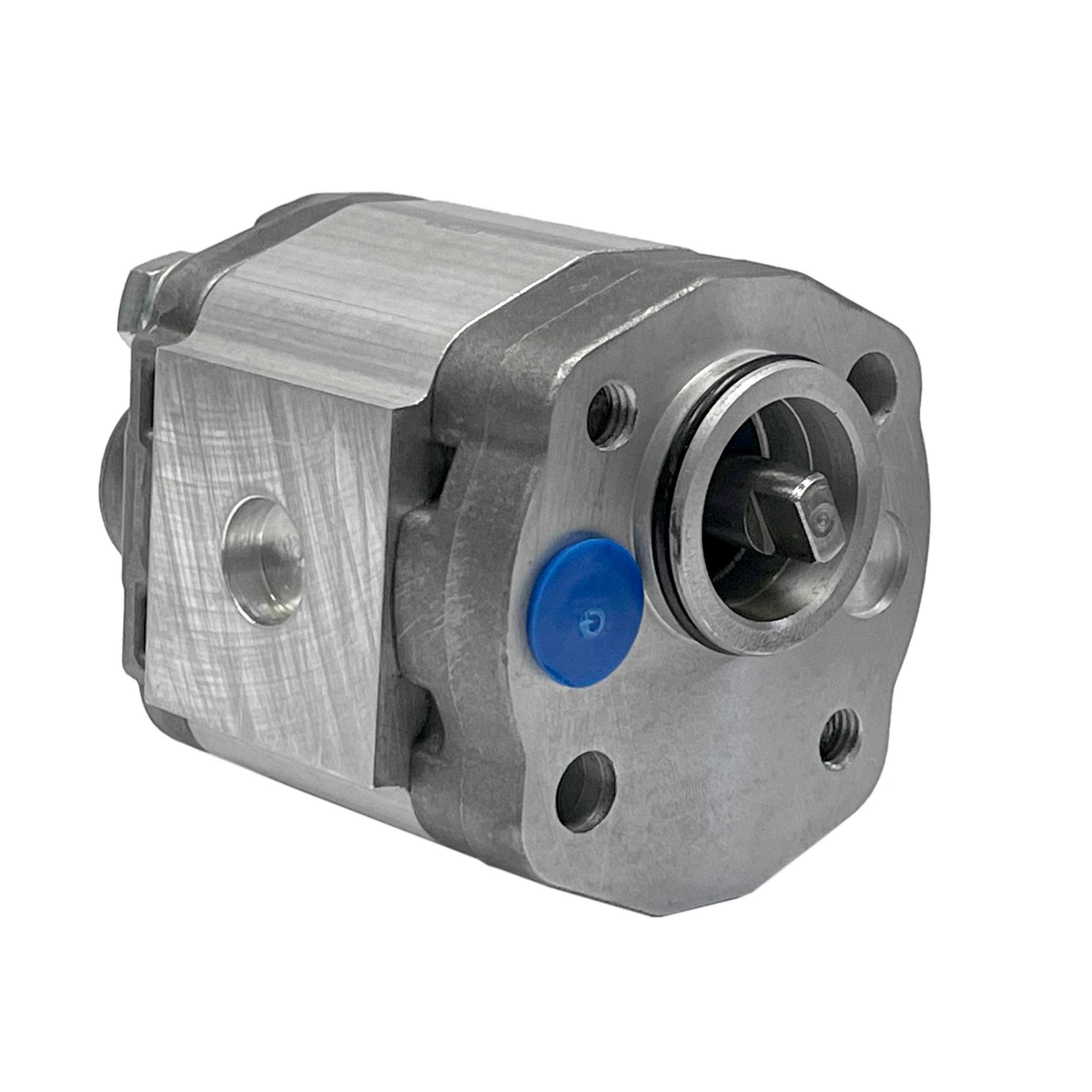
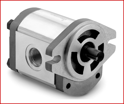
A gear pump is a type of positive displacement (PD) pump. It moves a fluid by repeatedly enclosing a fixed volume using interlocking cogs or gears, transferring it mechanically using a cyclic pumping action. It delivers a smooth pulse-free flow proportional to the rotational speed of its gears.
Gear pumps use the actions of rotating cogs or gears to transfer fluids. The rotating element develops a liquid seal with the pump casing and creates suction at the pump inlet. Fluid, drawn into the pump, is enclosed within the cavities of its rotating gears and transferred to the discharge. There are two basic designs of gear pump: external and internal(Figure 1).
An external gear pump consists of two identical, interlocking gears supported by separate shafts. Generally, one gear is driven by a motor and this drives the other gear (the idler). In some cases, both shafts may be driven by motors. The shafts are supported by bearings on each side of the casing.
As the gears come out of mesh on the inlet side of the pump, they create an expanded volume. Liquid flows into the cavities and is trapped by the gear teeth as the gears continue to rotate against the pump casing.
No fluid is transferred back through the centre, between the gears, because they are interlocked. Close tolerances between the gears and the casing allow the pump to develop suction at the inlet and prevent fluid from leaking back from the discharge side (although leakage is more likely with low viscosity liquids).
An internal gear pump operates on the same principle but the two interlocking gears are of different sizes with one rotating inside the other. The larger gear (the rotor) is an internal gear i.e. it has the teeth projecting on the inside. Within this is a smaller external gear (the idler –only the rotor is driven) mounted off-centre. This is designed to interlock with the rotor such that the gear teeth engage at one point. A pinion and bushing attached to the pump casing holds the idler in position. A fixed crescent-shaped partition or spacer fills the void created by the off-centre mounting position of the idler and acts as a seal between the inlet and outlet ports.
As the gears come out of mesh on the inlet side of the pump, they create an expanded volume. Liquid flows into the cavities and is trapped by the gear teeth as the gears continue to rotate against the pump casing and partition.
Gear pumps are compact and simple with a limited number of moving parts. They are unable to match the pressure generated by reciprocating pumps or the flow rates of centrifugal pumps but offer higher pressures and throughputs than vane or lobe pumps. Gear pumps are particularly suited for pumping oils and other high viscosity fluids.
Of the two designs, external gear pumps are capable of sustaining higher pressures (up to 3000 psi) and flow rates because of the more rigid shaft support and closer tolerances. Internal gear pumps have better suction capabilities and are suited to high viscosity fluids, although they have a useful operating range from 1cP to over 1,000,000cP. Since output is directly proportional to rotational speed, gear pumps are commonly used for metering and blending operations. Gear pumps can be engineered to handle aggressive liquids. While they are commonly made from cast iron or stainless steel, new alloys and composites allow the pumps to handle corrosive liquids such as sulphuric acid, sodium hypochlorite, ferric chloride and sodium hydroxide.
External gear pumps can also be used in hydraulic power applications, typically in vehicles, lifting machinery and mobile plant equipment. Driving a gear pump in reverse, using oil pumped from elsewhere in a system (normally by a tandem pump in the engine), creates a hydraulic motor. This is particularly useful to provide power in areas where electrical equipment is bulky, costly or inconvenient. Tractors, for example, rely on engine-driven external gear pumps to power their services.
Gear pumps are self-priming and can dry-lift although their priming characteristics improve if the gears are wetted. The gears need to be lubricated by the pumped fluid and should not be run dry for prolonged periods. Some gear pump designs can be run in either direction so the same pump can be used to load and unload a vessel, for example.
The close tolerances between the gears and casing mean that these types of pump are susceptible to wear particularly when used with abrasive fluids or feeds containing entrained solids. However, some designs of gear pumps, particularly internal variants, allow the handling of solids. External gear pumps have four bearings in the pumped medium, and tight tolerances, so are less suited to handling abrasive fluids. Internal gear pumps are more robust having only one bearing (sometimes two) running in the fluid. A gear pump should always have a strainer installed on the suction side to protect it from large, potentially damaging, solids.
Generally, if the pump is expected to handle abrasive solids it is advisable to select a pump with a higher capacity so it can be operated at lower speeds to reduce wear. However, it should be borne in mind that the volumetric efficiency of a gear pump is reduced at lower speeds and flow rates. A gear pump should not be operated too far from its recommended speed.
For high temperature applications, it is important to ensure that the operating temperature range is compatible with the pump specification. Thermal expansion of the casing and gears reduces clearances within a pump and this can also lead to increased wear, and in extreme cases, pump failure.
Despite the best precautions, gear pumps generally succumb to wear of the gears, casing and bearings over time. As clearances increase, there is a gradual reduction in efficiency and increase in flow slip: leakage of the pumped fluid from the discharge back to the suction side. Flow slip is proportional to the cube of the clearance between the cog teeth and casing so, in practice, wear has a small effect until a critical point is reached, from which performance degrades rapidly.
Gear pumps continue to pump against a back pressure and, if subjected to a downstream blockage will continue to pressurise the system until the pump, pipework or other equipment fails. Although most gear pumps are equipped with relief valves for this reason, it is always advisable to fit relief valves elsewhere in the system to protect downstream equipment.
Internal gear pumps, operating at low speed, are generally preferred for shear-sensitive liquids such as foodstuffs, paint and soaps. The higher speeds and lower clearances of external gear designs make them unsuitable for these applications. Internal gear pumps are also preferred when hygiene is important because of their mechanical simplicity and the fact that they are easy to strip down, clean and reassemble.
Gear pumps are commonly used for pumping high viscosity fluids such as oil, paints, resins or foodstuffs. They are preferred in any application where accurate dosing or high pressure output is required. The output of a gear pump is not greatly affected by pressure so they also tend to be preferred in any situation where the supply is irregular.
A gear pump moves a fluid by repeatedly enclosing a fixed volume within interlocking cogs or gears, transferring it mechanically to deliver a smooth pulse-free flow proportional to the rotational speed of its gears. There are two basic types: external and internal. An external gear pump consists of two identical, interlocking gears supported by separate shafts. An internal gear pump has two interlocking gears of different sizes with one rotating inside the other.
Gear pumps are commonly used for pumping high viscosity fluids such as oil, paints, resins or foodstuffs. They are also preferred in applications where accurate dosing or high pressure output is required. External gear pumps are capable of sustaining higher pressures (up to 7500 psi) whereas internal gear pumps have better suction capabilities and are more suited to high viscosity and shear-sensitive fluids.


 8613371530291