
what is pto hydraulic pump free sample
www.powermotiontech.com is using a security service for protection against online attacks. An action has triggered the service and blocked your request.
Please try again in a few minutes. If the issue persist, please contact the site owner for further assistance. Reference ID IP Address Date and Time 8bf2006c85a66667641f5dd58dcb3d35 63.210.148.230 03/07/2023 05:12 AM UTC
A: PTO stands for power take-off, which is an auxiliary clutch on the bottom of an industrial truck. These are used in construction applications. You see these big trucks with the water tanks on them going up and down and spraying water out the back. They’re using that for dust control.
Every now and then you’ll see one and it’s spraying way over on a freshly finished highway where they just laid grass or hydroseed. They’ll use that to irrigate and that’s basically what it’s for is construction and new construction of highways. Also dust control and irrigation for new sod along fresh highways.
While water covers over 70% of the earth not all of it is readily accessible to all locations. Water trucks often bring water where it’s needed the most. They carry thousands of gallons of water and disperse them using a PTO water truck pump.
Before we get into what a PTO water truck pump is and PTO for that matter, let’s talk about PTO water trucks. A water truck is essentially a water reservoir on wheels that can disperse water at a regulated volume. It is mainly used for irrigation or other watering applications where a fixed water source is not readily accessible.
The rig includes the cab area for a driver and often a single passenger seat for a helper. Also within this cab is a full control panel for controlling how water is dispersed.
When you’re dealing with new construction or mining you can be guaranteed that there will be a lot of displaced dirt. That dirt when the wind picks up can create a ton of dust when it’s very dry. On a large construction or mining site, dust can become a hazard. It can limit visibility to dangerous levels, cause respiratory issues and get out of control in general. Water trucks are an excellent solution to tamp down the dust with a light dousing of water.
PTO water trucks are also used for compaction on construction sites. When dirt is dug up and displaced it is often very uneven. That can be dangerous for heavy equipment, plus it makes it hard to create flat road surfaces. The trucks can add just the right amount of water distributed evenly so that a plate compacter can smooth the ground. If there’s too much water it will turn to sludge, if not enough water the soil particles will not stick to each other. With the controls on water trucks, the water flow can be precisely controlled.
Using PTO water trucks for irrigation became very popular between 2011 and 2017 due to a series of droughts along the west coast and in the Midwest. California, one of the hardest states hit, was struggling to keep crops in the central valley from drying up.
Irrigation isn’t just for the crops though; livestock suffer too when watering holes dry up. A water truck with its large capacity can remedy both. Before these long drought seasons, water trucks were mainly used in construction and mining.
PTO water trucks are used both in a precautionary role and a reactive role in firefighting applications. Especially in the country and rural areas that lack organized water sources such as hydrants. They’re not only used for putting out fires but also as a precaution against wildfires. Water trucks during the summer will frequently dampen areas prone to burn.
Bulk water delivery providers rely heavily on water trucks to deliver bulk water to their residential customers. Often used to fill swimming pools, and landscape water features, for example. This application is especially popular for residential properties under drought control or surviving on untreated water from a well. Rather than wait for days for a hose to fill a pool wasting well water, trucks bring in the water and get it done quickly. This also prevents damage or excess stress on the well pump.
As evident in the recent winter freeze here in Houston—natural disasters, extreme climate events, or hurricanes can cause a water shortage. In the aftermath of the recent storm, water trucks parked outside many communities for people to fill up water bottles. This helped families by providing water to drink, bathe with, and wash dishes until pipes were repaired.
Water trucks use a special type of pump that runs off the powerful engine these trucks have. The process is referred to as “power take-off or PTO for short. A power take-off (PTO) pump is used to convert the rotary power from the engine to hydraulic power to run the water pump. A PTO doesn’t just run pumps, on tractors they can also run cotton balers, power mowers, and more. In the city, you see PTO’s in use on street sweepers and fire truck pumps.
PTO pumps, also called trunk pumps connect directly to the truck’s driveshaft. It uses that rotary power and converts it with the PTO, into hydraulic power. The hydraulic power is used to power the PTO water pump which is typically connected on-frame and to the tank.
PTO pumps deliver water at a high-output, and their most unique benefit is the ability to capture the massive engine output of these trucks. This output is the source behind the pumps ability to move large amounts of water very quickly. There are other great benefits PTO pumps bring to the table:
If you’ve ever tried repairing a broken water pump you know it’s almost easier to just buy a new one. That’s why you have to take such great care in maintaining most water pumps—except PTO pumps. These pumps, since they use the power of the truck engine to drive them—are practically maintenance-free.
There’s no worries about gasoline breaking down the pump. No spark plugs to worry about changing, and PTO pumps are built from powder-coated steel to take a beating.
Because they are quite large and have extreme performance capabilities, some assume these pumps are hard to set up. However, you’d be surprised just how simple it is.
Simply follow the instructions to mount the pump, connect it to the driveshaft and be about your business. They don’t even require many tools for setup and teardown.
These pumps simply do not cut corners on power. In fact, the most powerful PTO pump in existence moves 30,000 gallons of water an hour (GPH). GPH capability is typically the most important factor when choosing the right PTO pump for your application. However, keep in mind most PTO pumps measure capacity in gallons per minute (GPM).
Whether you have a single water truck or a fleet of 20 trucks for your contracting company, we’ve got you covered. Gulf Coast only carries the best pumps from legendary manufacturers such as Goulds. Contact us today and let us show you our selection and help you get the pump you need.

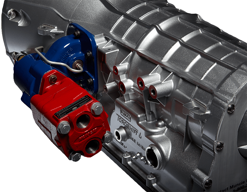
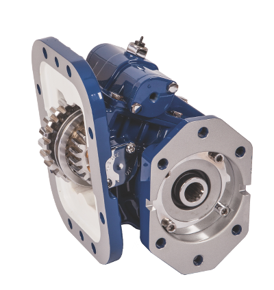
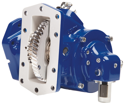
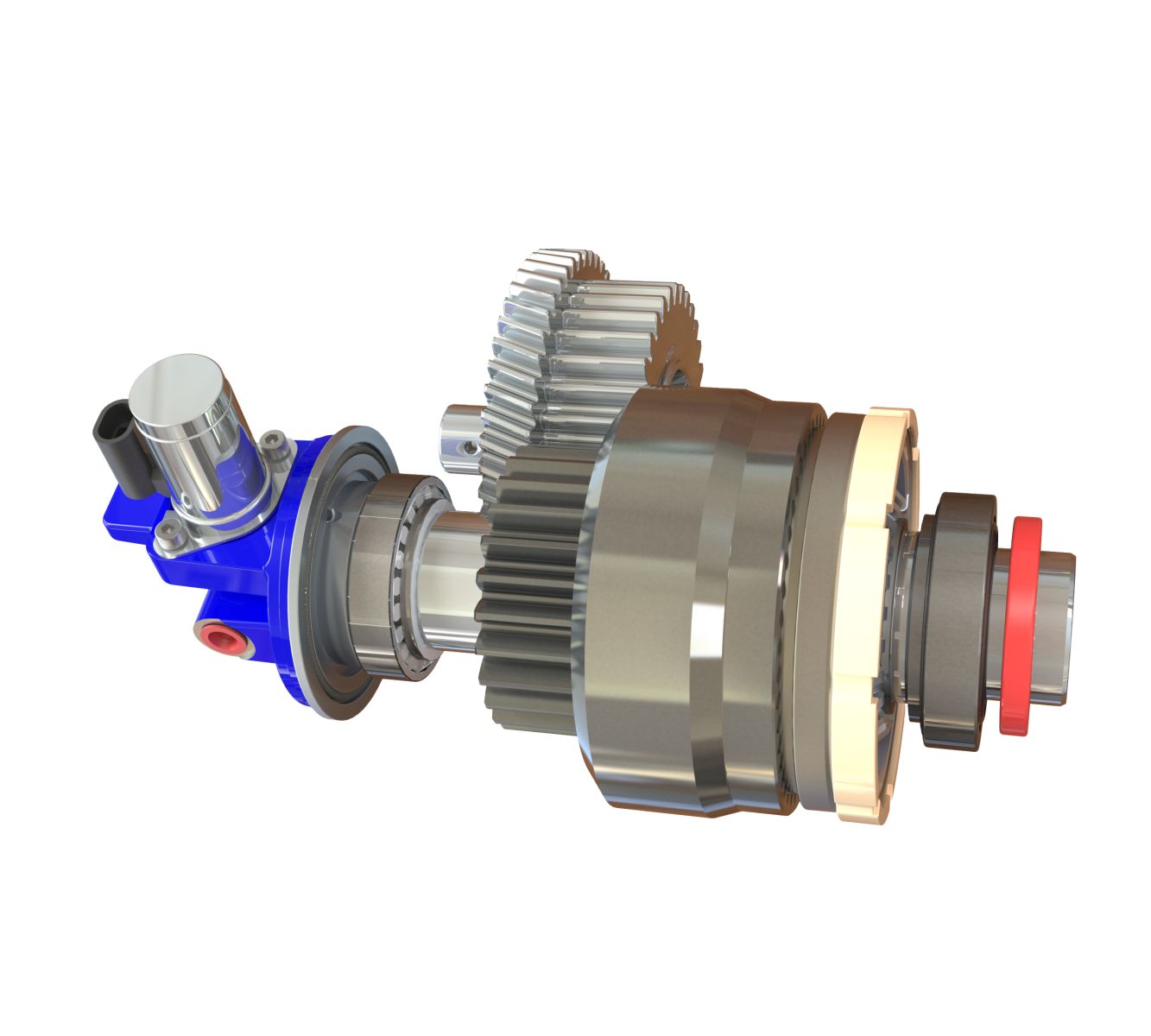
Powering a hydraulic pump to a power take-off (PTO) is a common practice. Within mobile hydraulic applications, there are three types of hydraulic pump construction typically found including gear, piston and vane.
Gear pumps are the most common design used in truck mounted hydraulic systems, as the gear pump is relatively inexpensive with its fewer moving parts, ability to be easily serviced and greater tolerance to contamination than other designs.
A hydraulic pump for mobile applications, like the gear, piston or vane pump, can be either direct mounted to the PTO or remote mounted – using a driveline. While each type is a viable option for mounting a hydraulic pump, it is important to understand each type of mount to ensure an effective connection is made between the PTO and pump.
In a direct mount the hydraulic pump is mounted directly to the output flange of the PTO. Direct mounting is the most common type of installation in the mobile equipment industry. When direct mounting a pump it is necessary to:
Select the correct pump rotation to match the PTO output rotation or select what is known as a bi-rotational pump, which tends to have equally sized ports since either can be the inlet or outlet.
For mobile, truck mounted hydraulic systems the most common pump mount is the SAE B, which is a 7/8” diameter shaft with 13 splines – one of the standard pump mounting configurations established by the Society of Automotive Engineers (SAE).
Disadvantages to direct mounting a pump• Concealed maintenance points, which include periodic removal and replacement of grease at the pump to PTO connection
Sometimes it is not possible to direct mount a hydraulic pump, requiring the pump to be remote mounted some distance away from the PTO and then powered from the power take-off by means of a driveline assembly. The correct type and series of driveline must be selected. Solid shafting is not recommended as it cannot be balanced and can vibrate, damaging the PTO and pump shaft seals – causing leaks. The better choice is a balanced, tubular assembly designed to meet the speed, torque and horsepower requirements of the application.
When using a driveline, it is important that it be in phase and incorporates a slip yoke at one end. Round, keyed PTO output shafts are susceptible to failure by high cyclic loading. An out of phase shaft will vibrate and damage the PTO and pump shaft seals while a functioning slip yoke will allow the shaft to adjust for flexing of the truck chassis. As part of a regularly scheduled, preventative maintenance plan, the slip yoke and bearings of the driveline must be lubricated.
As this type of installation has exposed rotating components it is important to make sure proper warning decals and guards are in place to protect workers.
Powering a pump to a PTO is a common practice, but selecting whether to direct or remote mount the pump takes understanding and careful consideration. Regardless of the type of mount you select, remember that this understanding of each mount – along with its advantages and its drawbacks – will be the key to creating an effective, lasting connection between the PTO and pump.
Josh Reimer has been with Muncie Power Products for 22 years. During his career with the company he has served in various capacities from shipping and receiving clerk to customer service manager to his current position as a market specialist and more. He holds four different certificates including those for lean implementer training and advanced facilitation training. When he’s not at work, Josh enjoys walking or hiking with his wife, Chasta.
It is recommended to begin analyzing a PTO application using pre-determined necessary technical information about the work output and installation requirements. Go through the following steps to specify a PTO.
Determine the transmission information being used (i.e. automatic or manual, make, model, side of installation). Parker Chelsea has an application guide that will help organize the necessary information needed. There are identification tags on the transmission itself that provide the make and model of the transmission which is required for the application worksheet.
Establish the approximate engine speed desired during operation or PTO ratio (if known). PTO speed is stated as a percentage of engine speed. An example being the required pump speed of 1000 RPM and having an engine operating speed of 1500 RPM. The percentage of PTO to engine speed would be calculated to approximately two-thirds, or approximately 67 percent (e.g. 1000/1500 = 66.67, or 67%).
Define the direction of the Driven Equipment Shaft Rotation with there being two choices, engine and opposite-engine. The PTO requirements will be determined by the driven equipment. It is important to note the PTO output shaft rotation listed on the application page is in relation to the vehicle crankshaft rotation as viewed from the rear of the vehicle.(See Figure 1).
Define the duty cycle as intermittent or continuous. Intermittent duty cycles are defined as PTO operations that last for less than five minutes in any fifteen-minute period. Conversely, continuous duty cycles are defined as PTO operations for more than five minutes out of every 15. If an intermittent PTO is used for continuous operation, the required torque must be divided by .70 to get the torque requirement for the driven equipment. The PTO will need to de-rated if it was not designed for continuous duty.
Determine the type and size of the PTO output required (i.e. driveshaft – the size of output required, direct mount pump – mounting flange and shaft type/size).
While not all information is always available, here is an informal guideline that can get you started with the right information to help you select the right PTO for your application.
It is important to remember when the appropriate PTO has been selected through the concluded gathered information, review the application guide, and make sure that all the necessary information has been included. When searching for a PTO in a catalog, please remember to read the footnotes as there may be additional information to consider for specifying a PTO. This can include transmissions not being able to withstand torque capacity of the PTO and the application or some other unique feature of the unit may be mentioned through the footnotes.
To further investigate what different PTOs are being offered, including the new 210 series PTO for the 2020 Ford Super Duty 10R140 Transmission, be sure to check out www.parker.com/chelsea to learn more.

This website is using a security service to protect itself from online attacks. The action you just performed triggered the security solution. There are several actions that could trigger this block including submitting a certain word or phrase, a SQL command or malformed data.

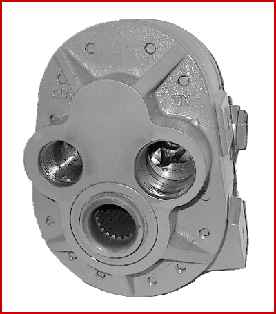
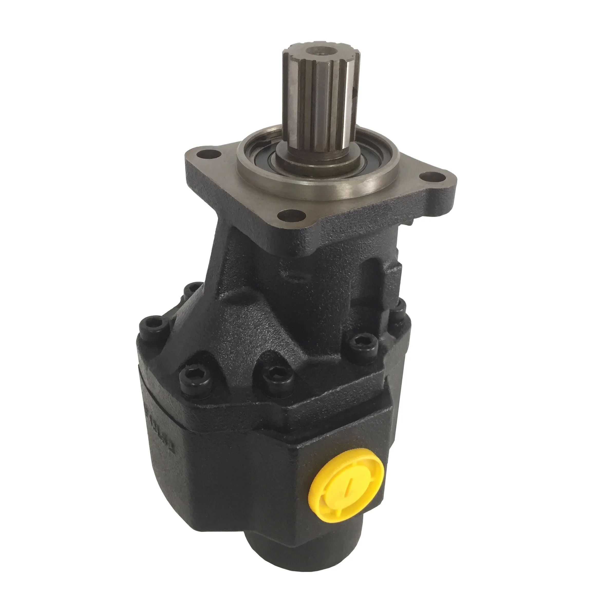
Model GP-PTO is a Power Take Off gear pump constructed with cast iron end plates and aluminium center section. It offers 4 displacement sizes from 3.41-9.76 in³/rev (56-160 cm³/rev). The standard drive is 1 3/8" diameter 6-tooth female spline.

Proper selection and installation of all hydraulic components in your winch system will ensure that your winch components perform as they should and are free of constant maintenance problems. Understanding the basic function, design, and components can help confirm proper selection and optimum usage for any hydraulic winch application.
The basic concept of any hydraulic system is simple: Force that is applied at one point is transmitted to another point using an incompressible fluid, yet every hydraulic system design will be unique to the application. A few hydraulic system components will be common for winch usages, such as pump/power take-offs and directional control valves.
The following component information is general in nature and will be helpful in choosing a hydraulic system design for a winch. It is always wise to consult a qualified hydraulic distributor, like Winches Inc, if you have specific questions about your system.
The hydraulic pump and PTO selected should be chosen to deliver the proper flow at any engine speed you want to run. For example, with an engine running at 1200 RPM, using a PTO which runs at 70% engine speed, a winch requiring 18 GPM flow for the line speed needed, the pump selected must be capable of delivering 18 GPM at 840 RPM, as that is what the PTO requires to operate. Also, the pump must be pressure rated for at least the setting of the relief valve.
Another important consideration on pump selection is to select the proper rotation. Most pumps are not bi-rotational; that is, they will function properly only in one direction of rotation. For example, if a PTO provides engine-wise rotation and the pump is mounted behind it with the shaft toward the front, a “right hand” or clockwise rotation of the pump is required. Other directions of mounting either the pump or PTO will affect the direction of rotation, so they must be considered in your selection.
The typical directional control valve to be used with a winch is a three-position, four-way valve with an open center spool which is spring returned in neutral. The open center spool is often referred to as a “motor” spool since its most common function is providing flow to hydraulic motors. In most winch applications, the spool should be spring returned to neutral, since this serves as a safety feature. As soon as the operator’s hand is removed from the valve lever the winch will stop running.

Things like restrictions and blockages can impede the flow of fluid to your pump. which could contribute to poor fluid flow. Air leak in suction line. Air present in the pump at startup. Insufficient supply of oil in pump. Clogged or dirty fluid filters. Clogged inlet lines or hoses. Blocked reservoir breather vent. Low oil in the reservoir
Now that we’ve ensured that the directional control is not reversed, it’s time to check that the drive motor itself is turning in the right direction. Sometimes incorrect installation leads to mismatched pipe routings between control valves and motors, which can reverse the direction of flow. Check to see that the motor is turning the pump in the right direction and if not - look at your piping.
Check to ensure that your pump drive motor is turning over and is developing the required speed and torque. In some cases, misalignment can cause binding of the drive shaft, which can prevent the motor from turning. If this is the case, correct the misalignment and inspect the motor for damage. If required, overhaul or replace motor.
Check to ensure the pump to motor coupling is undamaged. A sheared pump coupling is an obvious cause of failure, however the location of some pumps within hydraulic systems makes this difficult to check so it may go overlooked
It is possible that the entire flow could be passing over the relief valve, preventing the pressure from developing. Check that the relief valve is adjusted properly for the pump specifications and the application.
Seized bearings, or pump shafts and other internal damage may prevent the pump from operating all together. If everything else checks out, uncouple the pump and motor and check to see that the pump shaft is able to turn. If not, overhaul or replace the pump.
If your pump is having problems developing sufficient power, following this checklist will help you to pinpoint the problem. In some cases you may find a simple solution is the answer. If your pump is exhibiting any other issues such as noise problems, heat problems or flow problems, you may need to do some more investigation to address the root cause of your pump problem. To help, we’ve created a downloadable troubleshooting guide containing more information about each of these issues. So that you can keep your system up and running and avoid unplanned downtime. Download it here.
Hydraulic pumps are used in hydraulic drive systems and can be hydrostatic or hydrodynamic. A hydraulic pump is a mechanical source of power that converts mechanical power into hydraulic energy (hydrostatic energy i.e. flow, pressure). It generates flow with enough power to overcome pressure induced by the load at the pump outlet. When a hydraulic pump operates, it creates a vacuum at the pump inlet, which forces liquid from the reservoir into the inlet line to the pump and by mechanical action delivers this liquid to the pump outlet and forces it into the hydraulic system.
Hydrostatic pumps are positive displacement pumps while hydrodynamic pumps can be fixed displacement pumps, in which the displacement (flow through the pump per rotation of the pump) cannot be adjusted, or variable displacement pumps, which have a more complicated construction that allows the displacement to be adjusted. Hydrodynamic pumps are more frequent in day-to-day life. Hydrostatic pumps of various types all work on the principle of Pascal"s law.
Gear pumps (with external teeth) (fixed displacement) are simple and economical pumps. The swept volume or displacement of gear pumps for hydraulics will be between about 1 to 200 milliliters. They have the lowest volumetric efficiency (η
A rotary vane pump is a positive-displacement pump that consists of vanes mounted to a rotor that rotates inside a cavity. In some cases these vanes can have variable length and/or be tensioned to maintain contact with the walls as the pump rotates. A critical element in vane pump design is how the vanes are pushed into contact with the pump housing, and how the vane tips are machined at this very point. Several type of "lip" designs are used, and the main objective is to provide a tight seal between the inside of the housing and the vane, and at the same time to minimize wear and metal-to-metal contact. Forcing the vane out of the rotating centre and towards the pump housing is accomplished using spring-loaded vanes, or more traditionally, vanes loaded hydrodynamically (via the pressurized system fluid).
Screw pumps (fixed displacement) consist of two Archimedes" screws that intermesh and are enclosed within the same chamber. These pumps are used for high flows at relatively low pressure (max 100 bars (10,000 kPa)).ball valves
The major problem of screw pumps is that the hydraulic reaction force is transmitted in a direction that"s axially opposed to the direction of the flow.
Bent axis pumps, axial piston pumps and motors using the bent axis principle, fixed or adjustable displacement, exists in two different basic designs. The Thoma-principle (engineer Hans Thoma, Germany, patent 1935) with max 25 degrees angle and the Wahlmark-principle (Gunnar Axel Wahlmark, patent 1960) with spherical-shaped pistons in one piece with the piston rod, piston rings, and maximum 40 degrees between the driveshaft centerline and pistons (Volvo Hydraulics Co.). These have the best efficiency of all pumps. Although in general, the largest displacements are approximately one litre per revolution, if necessary a two-liter swept volume pump can be built. Often variable-displacement pumps are used so that the oil flow can be adjusted carefully. These pumps can in general work with a working pressure of up to 350–420 bars in continuous work.
By using different compensation techniques, the variable displacement type of these pumps can continuously alter fluid discharge per revolution and system pressure based on load requirements, maximum pressure cut-off settings, horsepower/ratio control, and even fully electro proportional systems, requiring no other input than electrical signals. This makes them potentially hugely power saving compared to other constant flow pumps in systems where prime mover/diesel/electric motor rotational speed is constant and required fluid flow is non-constant.
A radial piston pump is a form of hydraulic pump. The working pistons extend in a radial direction symmetrically around the drive shaft, in contrast to the axial piston pump.
Check that the electric motor is running. Although this is a simple concept, before you begin replacing parts, it’s critical that you make sure the electric motor is running. This can often be one of the easiest aspects to overlook, but it is necessary to confirm before moving forward.
Check that the pump shaft is rotating. Even though coupling guards and C-face mounts can make this difficult to confirm, it is important to establish if your pump shaft is rotating. If it isn’t, this could be an indication of a more severe issue, and this should be investigated immediately.
Check the oil level. This one tends to be the more obvious check, as it is often one of the only factors inspected before the pump is changed. The oil level should be three inches above the pump suction. Otherwise, a vortex can form in the reservoir, allowing air into the pump.
If the oil level is low, determine where the leak is in the system. Although this can be a difficult process, it is necessary to ensure your machines are performing properly. Leaks can be difficult to find.
What does the pump sound like when it is operating normally? Vane pumps generally are quieter than piston and gear pumps. If the pump has a high-pitched whining sound, it most likely is cavitating. If it has a knocking sound, like marbles rattling around, then aeration is the likely cause.
Cavitation is the formation and collapse of air cavities in the liquid. When the pump cannot get the total volume of oil it needs, cavitation occurs. Hydraulic oil contains approximately nine percent dissolved air. When the pump does not receive adequate oil volume at its suction port, high vacuum pressure occurs.
This dissolved air is pulled out of the oil on the suction side and then collapses or implodes on the pressure side. The implosions produce a very steady, high-pitched sound. As the air bubbles collapse, the inside of the pump is damaged.
While cavitation is a devastating development, with proper preventative maintenance practices and a quality monitoring system, early detection and deterrence remain attainable goals. UE System’s UltraTrak 850S CD pump cavitation sensor is a Smart Analog Sensor designed and optimized to detect cavitation on pumps earlier by measuring the ultrasound produced as cavitation starts to develop early-onset bubbles in the pump. By continuously monitoring the impact caused by cavitation, the system provides a simple, single value to trend and alert when cavitation is occurring.
The oil viscosity is too high. Low oil temperature increases the oil viscosity, making it harder for the oil to reach the pump. Most hydraulic systems should not be started with the oil any colder than 40°F and should not be put under load until the oil is at least 70°F.
Many reservoirs do not have heaters, particularly in the South. Even when heaters are available, they are often disconnected. While the damage may not be immediate, if a pump is continually started up when the oil is too cold, the pump will fail prematurely.
The suction filter or strainer is contaminated. A strainer is typically 74 or 149 microns in size and is used to keep “large” particles out of the pump. The strainer may be located inside or outside the reservoir. Strainers located inside the reservoir are out of sight and out of mind. Many times, maintenance personnel are not even aware that there is a strainer in the reservoir.
The suction strainer should be removed from the line or reservoir and cleaned a minimum of once a year. Years ago, a plant sought out help to troubleshoot a system that had already had five pumps changed within a single week. Upon closer inspection, it was discovered that the breather cap was missing, allowing dirty air to flow directly into the reservoir.
A check of the hydraulic schematic showed a strainer in the suction line inside the tank. When the strainer was removed, a shop rag was found wrapped around the screen mesh. Apparently, someone had used the rag to plug the breather cap opening, and it had then fallen into the tank. Contamination can come from a variety of different sources, so it pays to be vigilant and responsible with our practices and reliability measures.
The electric motor is driving the hydraulic pump at a speed that is higher than the pump’s rating. All pumps have a recommended maximum drive speed. If the speed is too high, a higher volume of oil will be needed at the suction port.
Due to the size of the suction port, adequate oil cannot fill the suction cavity in the pump, resulting in cavitation. Although this rarely happens, some pumps are rated at a maximum drive speed of 1,200 revolutions per minute (RPM), while others have a maximum speed of 3,600 RPM. The drive speed should be checked any time a pump is replaced with a different brand or model.
Every one of these devastating causes of cavitation threatens to cause major, irreversible damage to your equipment. Therefore, it’s not only critical to have proper, proactive practices in place, but also a monitoring system that can continuously protect your valuable assets, such as UE System’s UltraTrak 850S CD pump cavitation senor. These sensors regularly monitor the health of your pumps and alert you immediately if cavitation symptoms are present, allowing you to take corrective action before it’s too late.
Aeration is sometimes known as pseudo cavitation because air is entering the pump suction cavity. However, the causes of aeration are entirely different than that of cavitation. While cavitation pulls air out of the oil, aeration is the result of outside air entering the pump’s suction line.
Several factors can cause aeration, including an air leak in the suction line. This could be in the form of a loose connection, a cracked line, or an improper fitting seal. One method of finding the leak is to squirt oil around the suction line fittings. The fluid will be momentarily drawn into the suction line, and the knocking sound inside the pump will stop for a short period of time once the airflow path is found.
A bad shaft seal can also cause aeration if the system is supplied by one or more fixed displacement pumps. Oil that bypasses inside a fixed displacement pump is ported back to the suction port. If the shaft seal is worn or damaged, air can flow through the seal and into the pump’s suction cavity.
As mentioned previously, if the oil level is too low, oil can enter the suction line and flow into the pump. Therefore, always check the oil level with all cylinders in the retracted position.
If a new pump is installed and pressure will not build, the shaft may be rotating in the wrong direction. Some gear pumps can be rotated in either direction, but most have an arrow on the housing indicating the direction of rotation, as depicted in Figure 2.
Pump rotation should always be viewed from the shaft end. If the pump is rotated in the wrong direction, adequate fluid will not fill the suction port due to the pump’s internal design.
A fixed displacement pump delivers a constant volume of oil for a given shaft speed. A relief valve must be included downstream of the pump to limit the maximum pressure in the system.
After the visual and sound checks are made, the next step is to determine whether you have a volume or pressure problem. If the pressure will not build to the desired level, isolate the pump and relief valve from the system. This can be done by closing a valve, plugging the line downstream, or blocking the relief valve. If the pressure builds when this is done, there is a component downstream of the isolation point that is bypassing. If the pressure does not build up, the pump or relief valve is bad.
If the system is operating at a slower speed, a volume problem exists. Pumps wear over time, which results in less oil being delivered. While a flow meter can be installed in the pump’s outlet line, this is not always practical, as the proper fittings and adapters may not be available. To determine if the pump is badly worn and bypassing, first check the current to the electric motor. If possible, this test should be made when the pump is new to establish a reference. Electric motor horsepower is relative to the hydraulic horsepower required by the system.
For example, if a 50-GPM pump is used and the maximum pressure is 1,500 psi, a 50-hp motor will be required. If the pump is delivering less oil than when it was new, the current to drive the pump will drop. A 230-volt, 50-hp motor has an average full load rating of 130 amps. If the amperage is considerably lower, the pump is most likely bypassing and should be changed.
Figure 4.To isolate a fixed displacement pump and relief valve from the system, close a valve or plug the line downstream (left). If pressure builds, a component downstream of the isolation point is bypassing (right).
The most common type of variable displacement pump is the pressure-compensating design. The compensator setting limits the maximum pressure at the pump’s outlet port. The pump should be isolated as described for the fixed displacement pump.
If pressure does not build up, the relief valve or pump compensator may be bad. Prior to checking either component, perform the necessary lockout procedures and verify that the pressure at the outlet port is zero psi. The relief valve and compensator can then be taken apart and checked for contamination, wear, and broken springs.
Check the tank line temperature of the relief valve with a temperature gun or infrared camera. The tank line should be near ambient temperature. If the line is hot, the relief valve is either stuck partially open or is set too low.
Install a flow meter in the case drain line and check the flow rate. Most variable displacement pumps bypass one to three percent of the maximum pump volume through the case drain line. If the flow rate reaches 10 percent, the pump should be changed. Permanently installing a flow meter in the case drain line is an excellent reliability and troubleshooting tool.
Ensure the compensator is 200 psi above the maximum load pressure. If set too low, the compensator spool will shift and start reducing the pump volume when the system is calling for maximum volume.
Performing these recommended tests should help you make good decisions about the condition of your pumps or the cause of pump failures. If you change a pump, have a reason for changing it. Don’t just do it because you have a spare one in stock.
Conduct a reliability assessment on each of your hydraulic systems so when an issue occurs, you will have current pressure and temperature readings to consult.
Al Smiley is the president of GPM Hydraulic Consulting Inc., located in Monroe, Georgia. Since 1994, GPM has provided hydraulic training, consulting and reliability assessments to companies in t...
PTO is one of the most critical components in the truck hydraulic system. It is accountable for transferring mechanical energy from the hydraulic pump to auxiliary parts for executing given applications. However, a slight issue with the truck PTO hydraulic pump can cause system failure resulting in loss of revenue.
If you"re noticing whining or high-pitched sound – it could be because PTO"s gears are not appropriately merged or being too tight, issues with bearings or hydraulics. However, the clattering sound indicates that gears are too loose or have torsional vibrations.
In general, PTO hydraulic pump"s engagement issues could cause due to blocked hoses or bad fittings, connections, or the solenoid. In addition, mechanical engagement could generate from low air pressure, backlash too tight or improper cable deployment.
Once identifying the symptoms, it needs to operate rightly to enhance the vehicle"s life. Routine and scheduled maintenance is essential to ensure the PTO tool functions trouble-free. In this blog, we"ve outlined the maintenance steps for helping the end-users.
Before starting maintenance tasks, you should stop the vehicle, and the engine must be off, the wheels chalked, and a vehicle parked in a safe place. That"s because working under rotating elements is very dangerous. Opting for safe practices and adhering to all safety warnings eventually help avoid mishaps.
The PTO maintenance is divided primarily into three stages. The initial stage, short-term and system stages. The maintenance process needs adequate planning, operational expertise and thorough system knowledge. So, keep that in mind before the initiation of the process of vehicle maintenance.
The first step should be carried out within 24 to 48 hours of use or after experiencing symptoms of PTO hydraulic system damage. It would be best to analyse drive train sound if it seems louder than usual – it means further investigation may be required.
Further in the process, after cooling down the engine, look for potential damage such as leaks. These leaks could impact the transmission fluid level and affect the system performance over time. The PTOs must be checked within a week of installation for making sure that its mounting bolts have been torqued appropriately.
After the initial check-up, the truck operator needs to think about the next maintenance schedule based on the duty cycle. Usually, the duty cycles are divided into normal or severe duties. When the PTO operates five minutes extra out of every 15 minutes, it is defined as a severe duty. Lower than that compared as a normal duty. You can choose which duty cycle is ideal for long-term maintenance based on PTO performance.
The more complex a truck PTO hydraulic pump works, the more it needs to be inspected. Based on previous maintenance, the normal duty cycle inspects which items need replacement, checks the fluid level, or verifies that the equipment is tight and secure.
Long-term PTO maintenance is essential, suggested by vehicle manufacturers. It can help improve the performance of the hydraulic pump. Check fasteners are torqued rightly, and no fluid is leaking around the seal. If you find any leak source, seals need replacement.
Keeping the vehicle in optimal condition and PTO functioning requires periodic maintenance. When regular maintenance is carried out on the vehicle chassis (frame), it will be good to inspect the PTO of the hydraulic system.
During a weekly or monthly maintenance schedule, along with other components, PTO is checked for cleaned shaft proper lubrication. The application of lube simplifies parts engagement and disengagement issues. Applying an anti-seize grease helps smoothen parts movement in high-temperature cases. Also, make sure to clean off the grease fitting once the lube is applied.
In regular maintenance, timely inspections are also essential to determine whether the parts are running as expected. Here is what you can do with the help of experts.
Visual Inspection – To make the equipment run smoothly, the PTO inspection needs to be performed weekly or monthly. The inspections include checking for leaks, wear or tear, making sure the hose and wire are not rubbing against the transmission. Through visual inspections, you can prevent many issues immediately.
Physical Inspection –When it comes to checking the condition of PTO – physical inspection is equally important. It is suggested to perform after 100 hours of use. If you have removed the PTO from the hydraulic system for inspection, check the wear patterns and bearings. The periodic physical inspection could reduce the amount of downtime and expenses.
Surya Truck Parts – Your Trusted Online Supplier for Heavy Truck PartsWe are one of the best market leaders in Power Take-Off (PTO) products for the truck and mobile vocational markets. We are an establishedsupplier,having years of experience serving customers with the best and most affordable products.
We offer a complete range of PTO hydraulic system parts to match your needs. At Surya Trucks, you can enjoy cost benefits and get crucial components like PTO wet kit for sale.
Over the years, revolutionary advancements have been instigated in the tractor control systems’ field. These changes are primarily attributed to integrating various hydraulic inventions in the tipping trailer, braking system, implementing control structure, and steering to enhance this machinery’s optimum functionality. Hydraulic flow and pressure can be translated to motion and forces that enhance a tractor’s capacity to execute tasks that operators cannot perform manually or physically (Gannon, 2017). This paper provides a comprehensive discussion of tractor hydraulics and highlights the benefits of this particular technology.
There are two forms of hydraulic systems: the open- and closed-center structures. The latter is typical in modern-day farm equipment; this includes most tractor models. When in neutral, this system’s closed center valve obstructs oil flow from the pump. This fluid travels to an accumulator, which typically stores it under pressure. The valves also block fluid flow via the center when the hydraulic is in the aforementioned state. A variable flow pump also halts its operation following the closure of the valve. Open hydraulic structures were commonly used in most of the preliminary tractors. When in neutral, this system’s open-center valves link all lines back to the reservoir, directly bypassing the pump, which is always in operation, fostering the constant flow of oil without accumulating pressure. Valves also allow the flow of fluid through the center and into the reservoir during this particular.
Hydraulic oil, particularly non-pressurized fluid, is usually stored in the reservoir. According to Moinfar and Shahgholi (2018), reservoirs are usually vented towards the atmosphere to acclimatize the changing levels of oil. The air vent is fitted with filters to impede the entry of dust or dirt into the reservoir. The reservoir’s metallic walls enhance the cooling process of the fluid by improving the outflow of heat. The decreased pressure within this structure also gives room for dissolved or trapped air to escape from the hydraulic fluid. A sufficient surface area is also essential to foster the dispersal of heat.
JIC and NPTF fittings prevent hydraulic components’ port leakage. NPTF taper pipe threads hinder seepage by using the male-to-female resistance thread taper. On the other hand, JICs sue O-ring (Moinfar & Shahgholi, 2018). The brake hydraulic system’s components are usually joined using hoses and lines. The latter connects the hydraulic system’s stationary parts while hoses consolidate in motion. The hose, tubing, or pipe’s size is crucial (Moinfar & Shahgholi, 2018). If the hose’s size is minimal, the flow of oil increases rapidly, generating heat and causing the fluid to lose power. The cost and time for installing a large hose, on the other hand, can be too high.
The hydraulic pump plays a crucial role in enhancing fluid transmission from the reservoir and towards the hydraulic system. This process elevates the fluid’s energy level by triggering significant surges in its pressure. A one-phase pump typically has a single flow rate and one maximal pressure. These pumps are usually attached to the PTO shaft or crankshaft on a farm tractor. These pumps are often fitted on manual loaders and backhoes. On the other hand, a two-step pump first generates high fluid volumes by enhancing the cylinder’s rapid in-and-out movements. In case of any form of resistance, an additional gear set is used to create high pressure for splitting and lifting. Nonetheless, the fluid’s volume will reduce significantly during this phase.
Examples of valves fitted in the hydraulic system of a tractor include the flow, pressure, and direction control valve. They function by stopping or impeding liquid or pressure flow and controlling the quantity, pressure, and direction of flow. The motor is located within the pump’s power source, i.e., the cylinder. The fluid with high-pressure levels exerts its action on the piston and rod located within the hydraulic cylinder (Gosaye et al., 2015). Each cylinder stroke converts or translates the power or pressure of the fluid into mechanical force or work. While the piston and rod extend, the reservoir’s oil levels decrease, and when these two devices retract, the fluid flows back to the reservoir.
The pressure is typically applied or exerted on one region of the piston in single-acting cylinders; thus, mechanical force occurs in a single direction only. The cylinder then assumes its initial position under the load’s weight. Contrarily, pressure may be exerted on both sides of the piston in double-acting cylinders. Consequently, work takes place in either direction. The fixed ends in welded cylinders are usually welded to increase the durability and strength for high-pressure functions. Four rods are typically used to hold tie-rod cylinders together.
The instigation of hydraulics triggered significant changes in the agricultural industry, especially concerning the manner and method of production. The adoption of this technology has triggered substantial reductions in the level of manual power or effort needed to perform farm-related activities both in terms of work animals and workers (“How Hydraulics Transformed,” 2019). The tractor has also been effective in decreasing the risks associated with farm-related injuries by minimizing the number of hours individuals spend working in agricultural fields. This invention has also helped restrict the downtime rate amid agricultural operations. Furthermore, it has been crucial in promoting personal and overall productivity and efficiency during practice.
Significant advancements in agricultural engineering, particularly in tractor hydraulics, have triggered farm-related practices’ efficacy and efficiency. The tractor hydraulic system has several components, including the reservoir, pump, and motor. Hydraulics foster a tractor operator’s capacity to execute tasks that demand substantial effort with an electrical switch flip or simple lever push, which, in turn, actuates the hydraulic circuit. Contemporary farming integrates the use of hydraulics for operations that were initially controlled by mechanical means.
Gosaye, C., Mengiste, Z., & Hailu, A. (2015). Evaluation of the compatibility of tractors and implements at Tendaho Sugar Estate. ARPN Journal of Science and Technology, 5(10), 476–483. Web.

The Bezares 4200 Series Mechanical PTO is a dual output, eight-bolt, heavy-duty PTO with two independently air-operated outputs and a variety of ratio and output combinations. It is extremely versatile for many applications where two PTOs would be required.
Power Takeoff (PTO) units are complicated devices that perform many tasks on work trucks, but generally are used to provide power to hydraulic systems. There are more than a million PTO configurations depending on several factors, including the vehicle, the transmission, the application (work to be done), the required torque and horsepower needs to perform the work in a safe and efficient manner.
To further complicate matters, PTOs operate hydraulic systems which include a range of components for commercial vehicles, including pumps, fittings, tanks, valves and other related mobile power hydraulic components.
These challenges make selecting the right PTO a daunting task, without factoring in changing technology, new products, and changing application demands for vehicles. However, specialty companies who focus on the mobile power hydraulic market, like Eaton and others, can help ensure customers have the right mobile power system, including the PTO, for the job to be done.
One of the first decisions to make when spec’ing a PTO is how fast you want to run the engine when performing work. For example, if it’s a blower system, you must determine the torque specifications required to operate efficiently. Then you must match the vehicle’s transmission to the PTO and determine the best mounting location.
Other factors that determine a proper PTO include whether the vehicle has a manual, automatic or automated transmission and, depending on its age, what type of electronic control unit (ECU) is installed, as the PTO may have to be programed for proper operation.
Further complicating the product identification process is that each PTO component and manufacturer comes with a different part number, different ratios, and specifications making the ordering process confusing.
It’s important to remember there are experts that can help. For example, Eaton has streamlined and simplified the process with its “End Dump wet kit” packages for the Bezares brand of Mobile Power products including Power Takeoff (PTO) units.
The currently established kits fit popular Eaton Fuller and Eaton Cummins transmissions. The wet kits simplify the ordering and installation process by including all the components needed into a single part number. Offering all the needed components in one kit saves time to spec and receive compared to ordering individual parts and allows for a seamless installation.
Wet kits are installed on medium- and heavy-duty trucks that have accessories like booms and cranes that need hydraulic pumps to operate. The wet kits" hydraulic system is activated by the PTO mounted to the truck"s transmission.
Once installed properly, maintaining a mobile power system and PTO becomes a top priority. Failure to do so could lead to poor performance, unplanned down time, costly repairs, and more.
One rule of thumb for PTO maintenance is to have it inspected during normal or routine transmission maintenance, and make repairs, if needed, at that time. Since the PTO and transmission work together, inspecting and maintaining together can save time and money while ensure the efficient operation of your mobile power system.
Normal maintenance should include inspecting the connections between the pump and PTO for leaks, inspecting seals, cleaning and lubricating the shafts between the pump and PTO, and removing of any foreign objects, such as metal shavings, dirt and road grime. Looking for and repairing these commonly missed maintenance items will ensure the smooth operation of the system. Finally, receiving feedback from equipment operators is essential, as they are most likely to notice any unusual operation or noises and can help direct needed attention within the system.
Spec’ing the correct PTO for the vehicle and application, and properly maintaining it, will optimize performance and extend the lifecycle of the unit to provide years of reliable service.
About the author: Tim Bauer is vice president, Aftermarket, Vehicle Group North America at Eaton. He is responsible for all commercial aspects of the group’s aftermarket business. Bauer has extensive experience in the aftermarket business in both North America and Europe, and has held roles in sales, marketing, business development, operations, product strategy, and management.

If you ended up on this page doing normal allowed operations, please contact our support at support@mdpi.com. Please include what you were doing when this page came up and the Ray ID & Your IP found at the


 8613371530291