
what size hydraulic pump do i need free sample

We don"t collect information from our users. Only emails and answers are saved in our archive. Cookies are only used in the browser to improve user experience.
Some of our calculators and applications let you save application data to your local computer. These applications will - due to browser restrictions - send data between your browser and our server. We don"t save this data.
Google use cookies for serving our ads and handling visitor statistics. Please read Google Privacy & Terms for more information about how you can control adserving and the information collected.

- either it is the static lift from one height to an other or the total head loss component of the system - and can be calculated like Ph(kW) = q ρ g h / (3.6 106)
600 gpm of water is pumped a head of 110 ft. The efficiency ofthe pump i s 60% (0.6) and the specific gravity of water is 1. The pump shaft power can be calculated as
The shaft power - the power required transferred from the motor to the shaft of the pump - depends on the efficiency of the pump and can be calculated as Ps(kW) = Ph(kW)/ η (3)

Knowing how to right-size an electric motor for your hydraulic pump can help reduce energy consumption and increase operational efficiency. The key is to ensure the pump motor is operating at peak continuous load. But how can you know how much power is needed?
Before you can choose the correct electric motor, you must know how much horsepower (Hp) is required to drive the pump shaft. Generally, this is calculated by multiplying the flow capacity in gallons per minute (GPM) by the pressure in pounds per square inch (PSI). You then divide the resulting number by 1714 times the efficiency of the pump, for a formula that looks like this:
If you’re not sure how efficient your hydraulic pump is, it is advisable to use a common efficiency of about 85% (Multiplying 1714 x 0.85 = 1460 or 1500 if you round up). This work-around simplifies the formula to:
The above formula works in most applications with one notable exception: If the operating pressure of a pump is very low, the overall efficiency will be much lower than 85%. That’s because overall efficiency is equal to mechanical efficiency (internal mechanical friction) plus volumetric efficiency.
Internal friction is generally a fixed value, but volumetric efficiency changes depending on the pressure used. Low-pressure pumps have high volumetric efficiency because they are less susceptible to internal leakage. However, as the pressure goes up and internal fluids pass over work surfaces such as pistons, port plates, and lubrication points, the volumetric efficiency goes down and the amount of torque required to turn the pump for developing pressure goes up.
This variance makes it very important to know the efficiency of your pump if you’re using it at low pressure! Calculations that do not take low pressure into account will lead to a failed design.
If you calculate 20 GPM @ 300 PSI with an assumed overall efficiency of 89%, you would probably select a 5 Hp electric motor. However, if you calculate the same 20 GPM @ 300 PSI with the actual overall efficiency of 50%, you would know that you should be using a 7.5 Hp motor. In this example, making an assumption about the efficiency of your pump could result in installing a motor that is too large, driving up your overall operating cost.
There are many contributors to the overall efficiency of a hydraulic pump, and it pays to be as accurate as possible when choosing a motor. A best practice for proper sizing is to use published data from the pump vendor that shows actual input torque vs. pressure or overall efficiency vs pressure. Note that efficiency is also affected by RPM.
Identifying a right-sized motor for your hydraulic pump does not always ensure you are using the most efficient motor. Be sure to read Part 2 of this post to learn how RMS loading and Hp limiting can help you scale down the size of your electric motor to save money while maximizing efficiency.

www.powermotiontech.com is using a security service for protection against online attacks. An action has triggered the service and blocked your request.
Please try again in a few minutes. If the issue persist, please contact the site owner for further assistance. Reference ID IP Address Date and Time 8bf2006c85a66667641f5dd58dcb3d35 63.210.148.230 03/07/2023 04:58 AM UTC

Calculation of preliminary cooler capacity: Heat dissipation from hydraulic oil tanks, valves, pipes and hydraulic components is less than a few percent in standard mobile equipment and the cooler capacity must include some margins. Minimum cooler capacity, Ecooler = 0.25Ediesel
At least 25% of the input power must be dissipated by the cooler when peak power is utilized for long periods. In normal case however, the peak power is used for only short periods, thus the actual cooler capacity required might be considerably less. The oil volume in the hydraulic tank is also acting as a heat accumulator when peak power is used.
The system efficiency is very much dependent on the type of hydraulic work tool equipment, the hydraulic pumps and motors used and power input to the hydraulics may vary considerably. Each circuit must be evaluated and the load cycle estimated. New or modified systems must always be tested in practical work, covering all possible load cycles.
An easy way of measuring the actual average power loss in the system is to equip the machine with a test cooler and measure the oil temperature at the cooler inlet, the oil temperature at the cooler outlet and the oil flow through the cooler, when the machine is in normal operating mode. From these figures the test cooler power dissipation can be calculated and this is equal to the power loss when temperatures are stabilized. From this test the actual required cooler can be calculated to reach specified oil temperature in the oil tank. One problem can be to assemble the measuring equipment in-line, especially the oil flow meter.

Whether gear, vane, or piston pump, there may come a time when you have to replace your hydraulic pump. When your equipment isn’t working properly and you have narrowed the problem down to a hydraulic pump that needs to be replaced, what do you need to know?
The pump may simply be worn out—they do have a natural lifespan, as they are a wearable item in a hydraulic system. Although it is not possible to give an average lifespan given the different types of pumps and widely varying hours of operation; in general, you can expect many years of good operation from a hydraulic pump in most truck-mounted hydraulic systems. However, the life of a hydraulic pump might be much longer than what you are experiencing. Here are some questions you should ask:
Has the equipment been operating acceptably with this pump for a number of years without incident, and has the decline in performance been gradual over a longer period of time?
In this case, you’ll need to get the pump make and model number so that you can make sure that your replacement will be correct—either with an exact replacement or with another make that has the same operating specifications.
In any case, when replacing a failed hydraulic pump you will want to make sure to use this opportunity to also change out your hydraulic fluid (or at the very least use a filter cart and filter your oil). In the process of failing, your pump has introduced contaminants into your hydraulic system that you want to remove before they damage your new pump or any other hydraulic component. You will want to change your filter element(s) when you install your new pump, and then change it (them) out after a break-in period on your new pump.
If not, then let’s make sure there is not something else going on, or you may just find yourself replacing pumps frequently because the underlying problem hasn’t been addressed.
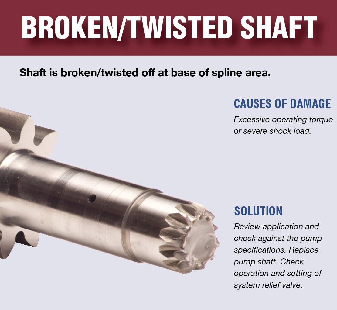
Input shaft is twisted/bcanroken: This occurs due to an extreme shock load to the pump. Typically, this happens when a relief valve is missing from the system, not functioning correctly, set to a much higher value than what the pump can withstand, or is too small for the system flow and thus cannot function correctly.
Shaft fretting:Fretting corrosion occurs under load in the presence of repeated relative surface motion, for example by vibration. Direct mount pump splines can be worn away. The solutions include:
Using larger pump and PTO shafts will not eliminate fretting, but may resolve the problem because of the increased metal available before the failure occurs.
Check to see that there is a sufficient amount of oil in the reservoir. Not just when the system is at rest, but also when all cylinders are extended to their maximum length or when all the components are running.
Make sure that the pump is able to get a good flow of oil from the reservoir—pumps are designed to have the oil feed pushed to the pump by gravity and atmospheric pressure, not by “sucking” oil. If the oil level in the reservoir is lower than the inlet of the pump, or the run too long or uphill, oil may not flow adequately to the pump. You can check if the pump is receiving oil adequately by using a vacuum gauge at the pump inlet. For a standard gear pump, at maximum operating RPM, the gauge should read a maximum of 5 inches HG. Larger numbers will damage a gear pump, and if you have a piston pump, the maximum number will be lower for good pump life.
Over pressurization: Pressure relief settings may have been adjusted or changed, and are now higher than what the pump can withstand without causing damage.
Pumps don’t produce pressure, they produce flow and are built to withstand pressure. When the system pressure exceeds the pump design, failure begins—either gradually or catastrophically.
When installing the new pump, back all the relief settings off. Then with the use of a pressure gauge T’d in at the pump outlet, gradually adjust the pressure relief setting until a cylinder or motor begins to move. Once the cylinder has reached the end of its stroke, gradually increase the pressure relief setting until reaching the max system pressure (which would be the pressure rating of the lowest rated component in the system). Sometimes, if a pump has been replaced and is larger than the original (produces more flow), the relief may not be able to allow all the flow being produced to escape back to tank. When that happens, the relief valve is “saturated” and the effect is the same as having no relief in the system. Pressures can reach levels much higher than the relief settings and components can be damaged or destroyed.
Contamination: Over time, the system oil has gotten dirty or contaminated and no longer is able to lubricate the pump, or is carrying contamination to the pump.
Make sure the oil is clean, the oil filer changed on schedule, and that there are no entry points for contamination like water, dust, or dirt from a reservoir filler cap that is unfiltered or missing, seals in motors or cylinders that are allowing contaminants in, etc.
New hoses can contain leftover bits of rubber and metal particles from the cutting and crimping process and should be cleaned out before installation.
Even new oil may be quite dirty if stored incorrectly, or exposed to dust and dirt. It’s always a good idea to use a filter cart and filter the system once it’s refilled with oil before turning on the system.
Hydraulic pumps are mechanisms in hydraulic systems that move hydraulic fluid from point to point initiating the production of hydraulic power. Hydraulic pumps are sometimes incorrectly referred to as “hydrolic” pumps.
They are an important device overall in the hydraulics field, a special kind of power transmission which controls the energy which moving fluids transmit while under pressure and change into mechanical energy. Other kinds of pumps utilized to transmit hydraulic fluids could also be referred to as hydraulic pumps. There is a wide range of contexts in which hydraulic systems are applied, hence they are very important in many commercial, industrial, and consumer utilities.
“Power transmission” alludes to the complete procedure of technologically changing energy into a beneficial form for practical applications. Mechanical power, electrical power, and fluid power are the three major branches that make up the power transmission field. Fluid power covers the usage of moving gas and moving fluids for the transmission of power. Hydraulics are then considered as a sub category of fluid power that focuses on fluid use in opposition to gas use. The other fluid power field is known as pneumatics and it’s focused on the storage and release of energy with compressed gas.
"Pascal"s Law" applies to confined liquids. Thus, in order for liquids to act hydraulically, they must be contained within a system. A hydraulic power pack or hydraulic power unit is a confined mechanical system that utilizes liquid hydraulically. Despite the fact that specific operating systems vary, all hydraulic power units share the same basic components. A reservoir, valves, a piping/tubing system, a pump, and actuators are examples of these components. Similarly, despite their versatility and adaptability, these mechanisms work together in related operating processes at the heart of all hydraulic power packs.
The hydraulic reservoir"s function is to hold a volume of liquid, transfer heat from the system, permit solid pollutants to settle, and aid in releasing moisture and air from the liquid.
Mechanical energy is changed to hydraulic energy by the hydraulic pump. This is accomplished through the movement of liquid, which serves as the transmission medium. All hydraulic pumps operate on the same basic principle of dispensing fluid volume against a resistive load or pressure.
Hydraulic valves are utilized to start, stop, and direct liquid flow in a system. Hydraulic valves are made of spools or poppets and can be actuated hydraulically, pneumatically, manually, electrically, or mechanically.
The end result of Pascal"s law is hydraulic actuators. This is the point at which hydraulic energy is transformed back to mechanical energy. This can be accomplished by using a hydraulic cylinder to transform hydraulic energy into linear movement and work or a hydraulic motor to transform hydraulic energy into rotational motion and work. Hydraulic motors and hydraulic cylinders, like hydraulic pumps, have various subtypes, each meant for specific design use.
The essence of hydraulics can be found in a fundamental physical fact: fluids are incompressible. (As a result, fluids more closely resemble solids than compressible gasses) The incompressible essence of fluid allows it to transfer force and speed very efficiently. This fact is summed up by a variant of "Pascal"s Principle," which states that virtually all pressure enforced on any part of a fluid is transferred to every other part of the fluid. This scientific principle states, in other words, that pressure applied to a fluid transmits equally in all directions.
Furthermore, the force transferred through a fluid has the ability to multiply as it moves. In a slightly more abstract sense, because fluids are incompressible, pressurized fluids should keep a consistent pressure just as they move. Pressure is defined mathematically as a force acting per particular area unit (P = F/A). A simplified version of this equation shows that force is the product of area and pressure (F = P x A). Thus, by varying the size or area of various parts inside a hydraulic system, the force acting inside the pump can be adjusted accordingly (to either greater or lesser). The need for pressure to remain constant is what causes force and area to mirror each other (on the basis of either shrinking or growing). A hydraulic system with a piston five times larger than a second piston can demonstrate this force-area relationship. When a force (e.g., 50lbs) is exerted on the smaller piston, it is multiplied by five (e.g., 250 lbs) and transmitted to the larger piston via the hydraulic system.
Hydraulics is built on fluids’ chemical properties and the physical relationship between pressure, area, and force. Overall, hydraulic applications allow human operators to generate and exert immense mechanical force with little to no physical effort. Within hydraulic systems, both oil and water are used to transmit power. The use of oil, on the other hand, is far more common, owing in part to its extremely incompressible nature.
Pressure relief valves prevent excess pressure by regulating the actuators’ output and redirecting liquid back to the reservoir when necessary. Directional control valves are used to change the size and direction of hydraulic fluid flow.
While hydraulic power transmission is remarkably useful in a wide range of professional applications, relying solely on one type of power transmission is generally unwise. On the contrary, the most efficient strategy is to combine a wide range of power transmissions (pneumatic, hydraulic, mechanical, and electrical). As a result, hydraulic systems must be carefully embedded into an overall power transmission strategy for the specific commercial application. It is necessary to invest in locating trustworthy and skilled hydraulic manufacturers/suppliers who can aid in the development and implementation of an overall hydraulic strategy.
The intended use of a hydraulic pump must be considered when selecting a specific type. This is significant because some pumps may only perform one function, whereas others allow for greater flexibility.
The pump"s material composition must also be considered in the application context. The cylinders, pistons, and gears are frequently made of long-lasting materials like aluminum, stainless steel, or steel that can withstand the continuous wear of repeated pumping. The materials must be able to withstand not only the process but also the hydraulic fluids. Composite fluids frequently contain oils, polyalkylene glycols, esters, butanol, and corrosion inhibitors (though water is used in some instances). The operating temperature, flash point, and viscosity of these fluids differ.
In addition to material, manufacturers must compare hydraulic pump operating specifications to make sure that intended utilization does not exceed pump abilities. The many variables in hydraulic pump functionality include maximum operating pressure, continuous operating pressure, horsepower, operating speed, power source, pump weight, and maximum fluid flow. Standard measurements like length, rod extension, and diameter should be compared as well. Because hydraulic pumps are used in lifts, cranes, motors, and other heavy machinery, they must meet strict operating specifications.
It is critical to recall that the overall power generated by any hydraulic drive system is influenced by various inefficiencies that must be considered in order to get the most out of the system. The presence of air bubbles within a hydraulic drive, for example, is known for changing the direction of the energy flow inside the system (since energy is wasted on the way to the actuators on bubble compression). Using a hydraulic drive system requires identifying shortfalls and selecting the best parts to mitigate their effects. A hydraulic pump is the "generator" side of a hydraulic system that initiates the hydraulic procedure (as opposed to the "actuator" side that completes the hydraulic procedure). Regardless of disparities, all hydraulic pumps are responsible for displacing liquid volume and transporting it to the actuator(s) from the reservoir via the tubing system. Some form of internal combustion system typically powers pumps.
While the operation of hydraulic pumps is normally the same, these mechanisms can be split into basic categories. There are two types of hydraulic pumps to consider: gear pumps and piston pumps. Radial and axial piston pumps are types of piston pumps. Axial pumps produce linear motion, whereas radial pumps can produce rotary motion. The gear pump category is further subdivided into external gear pumps and internal gear pumps.
Each type of hydraulic pump, regardless of piston or gear, is either double-action or single-action. Single-action pumps can only pull, push, or lift in one direction, while double-action pumps can pull, push, or lift in multiple directions.
Vane pumps are positive displacement pumps that maintain a constant flow rate under varying pressures. It is a pump that self-primes. It is referred to as a "vane pump" because the effect of the vane pressurizes the liquid.
This pump has a variable number of vanes mounted onto a rotor that rotates within the cavity. These vanes may be variable in length and tensioned to maintain contact with the wall while the pump draws power. The pump also features a pressure relief valve, which prevents pressure rise inside the pump from damaging it.
Internal gear pumps and external gear pumps are the two main types of hydraulic gear pumps. Pumps with external gears have two spur gears, the spurs of which are all externally arranged. Internal gear pumps also feature two spur gears, and the spurs of both gears are internally arranged, with one gear spinning around inside the other.
Both types of gear pumps deliver a consistent amount of liquid with each spinning of the gears. Hydraulic gear pumps are popular due to their versatility, effectiveness, and fairly simple design. Furthermore, because they are obtainable in a variety of configurations, they can be used in a wide range of consumer, industrial, and commercial product contexts.
Hydraulic ram pumps are cyclic machines that use water power, also referred to as hydropower, to transport water to a higher level than its original source. This hydraulic pump type is powered solely by the momentum of moving or falling water.
Ram pumps are a common type of hydraulic pump, especially among other types of hydraulic water pumps. Hydraulic ram pumps are utilized to move the water in the waste management, agricultural, sewage, plumbing, manufacturing, and engineering industries, though only about ten percent of the water utilized to run the pump gets to the planned end point.
Despite this disadvantage, using hydropower instead of an external energy source to power this kind of pump makes it a prominent choice in developing countries where the availability of the fuel and electricity required to energize motorized pumps is limited. The use of hydropower also reduces energy consumption for industrial factories and plants significantly. Having only two moving parts is another advantage of the hydraulic ram, making installation fairly simple in areas with free falling or flowing water. The water amount and the rate at which it falls have an important effect on the pump"s success. It is critical to keep this in mind when choosing a location for a pump and a water source. Length, size, diameter, minimum and maximum flow rates, and speed of operation are all important factors to consider.
Hydraulic water pumps are machines that move water from one location to another. Because water pumps are used in so many different applications, there are numerous hydraulic water pump variations.
Water pumps are useful in a variety of situations. Hydraulic pumps can be used to direct water where it is needed in industry, where water is often an ingredient in an industrial process or product. Water pumps are essential in supplying water to people in homes, particularly in rural residences that are not linked to a large sewage circuit. Water pumps are required in commercial settings to transport water to the upper floors of high rise buildings. Hydraulic water pumps in all of these situations could be powered by fuel, electricity, or even by hand, as is the situation with hydraulic hand pumps.
Water pumps in developed economies are typically automated and powered by electricity. Alternative pumping tools are frequently used in developing economies where dependable and cost effective sources of electricity and fuel are scarce. Hydraulic ram pumps, for example, can deliver water to remote locations without the use of electricity or fuel. These pumps rely solely on a moving stream of water’s force and a properly configured number of valves, tubes, and compression chambers.
Electric hydraulic pumps are hydraulic liquid transmission machines that use electricity to operate. They are frequently used to transfer hydraulic liquid from a reservoir to an actuator, like a hydraulic cylinder. These actuation mechanisms are an essential component of a wide range of hydraulic machinery.
There are several different types of hydraulic pumps, but the defining feature of each type is the use of pressurized fluids to accomplish a job. The natural characteristics of water, for example, are harnessed in the particular instance of hydraulic water pumps to transport water from one location to another. Hydraulic gear pumps and hydraulic piston pumps work in the same way to help actuate the motion of a piston in a mechanical system.
Despite the fact that there are numerous varieties of each of these pump mechanisms, all of them are powered by electricity. In such instances, an electric current flows through the motor, which turns impellers or other devices inside the pump system to create pressure differences; these differential pressure levels enable fluids to flow through the pump. Pump systems of this type can be utilized to direct hydraulic liquid to industrial machines such as commercial equipment like elevators or excavators.
Hydraulic hand pumps are fluid transmission machines that utilize the mechanical force generated by a manually operated actuator. A manually operated actuator could be a lever, a toggle, a handle, or any of a variety of other parts. Hydraulic hand pumps are utilized for hydraulic fluid distribution, water pumping, and various other applications.
Hydraulic hand pumps may be utilized for a variety of tasks, including hydraulic liquid direction to circuits in helicopters and other aircraft, instrument calibration, and piston actuation in hydraulic cylinders. Hydraulic hand pumps of this type use manual power to put hydraulic fluids under pressure. They can be utilized to test the pressure in a variety of devices such as hoses, pipes, valves, sprinklers, and heat exchangers systems. Hand pumps are extraordinarily simple to use.
Each hydraulic hand pump has a lever or other actuation handle linked to the pump that, when pulled and pushed, causes the hydraulic liquid in the pump"s system to be depressurized or pressurized. This action, in the instance of a hydraulic machine, provides power to the devices to which the pump is attached. The actuation of a water pump causes the liquid to be pulled from its source and transferred to another location. Hydraulic hand pumps will remain relevant as long as hydraulics are used in the commerce industry, owing to their simplicity and easy usage.
12V hydraulic pumps are hydraulic power devices that operate on 12 volts DC supplied by a battery or motor. These are specially designed processes that, like all hydraulic pumps, are applied in commercial, industrial, and consumer places to convert kinetic energy into beneficial mechanical energy through pressurized viscous liquids. This converted energy is put to use in a variety of industries.
Hydraulic pumps are commonly used to pull, push, and lift heavy loads in motorized and vehicle machines. Hydraulic water pumps may also be powered by 12V batteries and are used to move water out of or into the desired location. These electric hydraulic pumps are common since they run on small batteries, allowing for ease of portability. Such portability is sometimes required in waste removal systems and vehiclies. In addition to portable and compact models, options include variable amp hour productions, rechargeable battery pumps, and variable weights.
While non rechargeable alkaline 12V hydraulic pumps are used, rechargeable ones are much more common because they enable a continuous flow. More considerations include minimum discharge flow, maximum discharge pressure, discharge size, and inlet size. As 12V batteries are able to pump up to 150 feet from the ground, it is imperative to choose the right pump for a given use.
Air hydraulic pumps are hydraulic power devices that use compressed air to stimulate a pump mechanism, generating useful energy from a pressurized liquid. These devices are also known as pneumatic hydraulic pumps and are applied in a variety of industries to assist in the lifting of heavy loads and transportation of materials with minimal initial force.
Air pumps, like all hydraulic pumps, begin with the same components. The hydraulic liquids, which are typically oil or water-based composites, require the use of a reservoir. The fluid is moved from the storage tank to the hydraulic cylinder via hoses or tubes connected to this reservoir. The hydraulic cylinder houses a piston system and two valves. A hydraulic fluid intake valve allows hydraulic liquid to enter and then traps it by closing. The discharge valve is the point at which the high pressure fluid stream is released. Air hydraulic pumps have a linked air cylinder in addition to the hydraulic cylinder enclosing one end of the piston.
The protruding end of the piston is acted upon by a compressed air compressor or air in the cylinder. When the air cylinder is empty, a spring system in the hydraulic cylinder pushes the piston out. This makes a vacuum, which sucks fluid from the reservoir into the hydraulic cylinder. When the air compressor is under pressure, it engages the piston and pushes it deeper into the hydraulic cylinder and compresses the liquids. This pumping action is repeated until the hydraulic cylinder pressure is high enough to forcibly push fluid out through the discharge check valve. In some instances, this is connected to a nozzle and hoses, with the important part being the pressurized stream. Other uses apply the energy of this stream to pull, lift, and push heavy loads.
Hydraulic piston pumps transfer hydraulic liquids through a cylinder using plunger-like equipment to successfully raise the pressure for a machine, enabling it to pull, lift, and push heavy loads. This type of hydraulic pump is the power source for heavy-duty machines like excavators, backhoes, loaders, diggers, and cranes. Piston pumps are used in a variety of industries, including automotive, aeronautics, power generation, military, marine, and manufacturing, to mention a few.
Hydraulic piston pumps are common due to their capability to enhance energy usage productivity. A hydraulic hand pump energized by a hand or foot pedal can convert a force of 4.5 pounds into a load-moving force of 100 pounds. Electric hydraulic pumps can attain pressure reaching 4,000 PSI. Because capacities vary so much, the desired usage pump must be carefully considered. Several other factors must also be considered. Standard and custom configurations of operating speeds, task-specific power sources, pump weights, and maximum fluid flows are widely available. Measurements such as rod extension length, diameter, width, and height should also be considered, particularly when a hydraulic piston pump is to be installed in place of a current hydraulic piston pump.
Hydraulic clutch pumps are mechanisms that include a clutch assembly and a pump that enables the user to apply the necessary pressure to disengage or engage the clutch mechanism. Hydraulic clutches are crafted to either link two shafts and lock them together to rotate at the same speed or detach the shafts and allow them to rotate at different speeds as needed to decelerate or shift gears.
Hydraulic pumps change hydraulic energy to mechanical energy. Hydraulic pumps are particularly designed machines utilized in commercial, industrial, and residential areas to generate useful energy from different viscous liquids pressurization. Hydraulic pumps are exceptionally simple yet effective machines for moving fluids. "Hydraulic" is actually often misspelled as "Hydralic". Hydraulic pumps depend on the energy provided by hydraulic cylinders to power different machines and mechanisms.
There are several different types of hydraulic pumps, and all hydraulic pumps can be split into two primary categories. The first category includes hydraulic pumps that function without the assistance of auxiliary power sources such as electric motors and gas. These hydraulic pump types can use the kinetic energy of a fluid to transfer it from one location to another. These pumps are commonly called ram pumps. Hydraulic hand pumps are never regarded as ram pumps, despite the fact that their operating principles are similar.
The construction, excavation, automotive manufacturing, agriculture, manufacturing, and defense contracting industries are just a few examples of operations that apply hydraulics power in normal, daily procedures. Since hydraulics usage is so prevalent, hydraulic pumps are unsurprisingly used in a wide range of machines and industries. Pumps serve the same basic function in all contexts where hydraulic machinery is used: they transport hydraulic fluid from one location to another in order to generate hydraulic energy and pressure (together with the actuators).
Elevators, automotive brakes, automotive lifts, cranes, airplane flaps, shock absorbers, log splitters, motorboat steering systems, garage jacks and other products use hydraulic pumps. The most common application of hydraulic pumps in construction sites is in big hydraulic machines and different types of "off-highway" equipment such as excavators, dumpers, diggers, and so on. Hydraulic systems are used in other settings, such as offshore work areas and factories, to power heavy machinery, cut and bend material, move heavy equipment, and so on.
Fluid’s incompressible nature in hydraulic systems allows an operator to make and apply mechanical power in an effective and efficient way. Practically all force created in a hydraulic system is applied to the intended target.
Because of the relationship between area, pressure, and force (F = P x A), modifying the force of a hydraulic system is as simple as changing the size of its components.
Hydraulic systems can transfer energy on an equal level with many mechanical and electrical systems while being significantly simpler in general. A hydraulic system, for example, can easily generate linear motion. On the contrary, most electrical and mechanical power systems need an intermediate mechanical step to convert rotational motion to linear motion.
Hydraulic systems are typically smaller than their mechanical and electrical counterparts while producing equivalents amounts of power, providing the benefit of saving physical space.
Hydraulic systems can be used in a wide range of physical settings due to their basic design (a pump attached to actuators via some kind of piping system). Hydraulic systems could also be utilized in environments where electrical systems would be impractical (for example underwater).
By removing electrical safety hazards, using hydraulic systems instead of electrical power transmission improves relative safety (for example explosions, electric shock).
The amount of power that hydraulic pumps can generate is a significant, distinct advantage. In certain cases, a hydraulic pump could generate ten times the power of an electrical counterpart. Some hydraulic pumps (for example, piston pumps) cost more than the ordinary hydraulic component. These drawbacks, however, can be mitigated by the pump"s power and efficiency. Despite their relatively high cost, piston pumps are treasured for their strength and capability to transmit very viscous fluids.
Handling hydraulic liquids is messy, and repairing leaks in a hydraulic pump can be difficult. Hydraulic liquid that leaks in hot areas may catch fire. Hydraulic lines that burst may cause serious injuries. Hydraulic liquids are corrosive as well, though some are less so than others. Hydraulic systems need frequent and intense maintenance. Parts with a high factor of precision are frequently required in systems. If the power is very high and the pipeline cannot handle the power transferred by the liquid, the high pressure received by the liquid may also cause work accidents.
Even though hydraulic systems are less complex than electrical or mechanical systems, they are still complex systems that should be handled with caution. Avoiding physical contact with hydraulic systems is an essential safety precaution when engaging with them. Even when a hydraulic machine is not in use, active liquid pressure within the system can be a hazard.
Inadequate pumps can cause mechanical failure in the place of work that can have serious and costly consequences. Although pump failure has historically been unpredictable, new diagnostic technology continues to improve on detecting methods that previously relied solely on vibration signals. Measuring discharge pressures enables manufacturers to forecast pump wear more accurately. Discharge sensors are simple to integrate into existing systems, increasing the hydraulic pump"s safety and versatility.
Hydraulic pumps are devices in hydraulic systems that move hydraulic fluid from point to point, initiating hydraulic power production. They are an important device overall in the hydraulics field, a special kind of power transmission that controls the energy which moving fluids transmit while under pressure and change into mechanical energy. Hydraulic pumps are divided into two categories namely gear pumps and piston pumps. Radial and axial piston pumps are types of piston pumps. Axial pumps produce linear motion, whereas radial pumps can produce rotary motion. The construction, excavation, automotive manufacturing, agriculture, manufacturing, and defense contracting industries are just a few examples of operations that apply hydraulics power in normal, daily procedures.

Once you have selected your cylinder. find the required reservoir capacity in the cylinder specification chart. and choose a hand pump with at least 10% more reservoir capacity per cylinder.
An R256 cylinder (page 11) has a required oil capacity of 527.6 cm3. The P42 hand pump (page 34) with a reservoir capacity of 737.4 cm3 can pump this cylinder to its full stroke. If two R256 cylinders are to be raised. use a P140 with a reservoir capacity of 2867.7 cm3 6.35 mm I.D. hose requires 32.2 cm3 oil per meter. 9.65 mm I.D. hose requires 69.9 cm3 per meter.
Once you have selected your cylinder. find the required reservoir capacity in the cylinder specification chart. and choose a hand pump with at least 10% more reservoir capacity per cylinder.
A gear pump is a type of positive displacement (PD) pump. It moves a fluid by repeatedly enclosing a fixed volume using interlocking cogs or gears, transferring it mechanically using a cyclic pumping action. It delivers a smooth pulse-free flow proportional to the rotational speed of its gears.
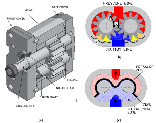
Gear pumps use the actions of rotating cogs or gears to transfer fluids. The rotating element develops a liquid seal with the pump casing and creates suction at the pump inlet. Fluid, drawn into the pump, is enclosed within the cavities of its rotating gears and transferred to the discharge. There are two basic designs of gear pump: external and internal(Figure 1).
An external gear pump consists of two identical, interlocking gears supported by separate shafts. Generally, one gear is driven by a motor and this drives the other gear (the idler). In some cases, both shafts may be driven by motors. The shafts are supported by bearings on each side of the casing.
As the gears come out of mesh on the inlet side of the pump, they create an expanded volume. Liquid flows into the cavities and is trapped by the gear teeth as the gears continue to rotate against the pump casing.
No fluid is transferred back through the centre, between the gears, because they are interlocked. Close tolerances between the gears and the casing allow the pump to develop suction at the inlet and prevent fluid from leaking back from the discharge side (although leakage is more likely with low viscosity liquids).
An internal gear pump operates on the same principle but the two interlocking gears are of different sizes with one rotating inside the other. The larger gear (the rotor) is an internal gear i.e. it has the teeth projecting on the inside. Within this is a smaller external gear (the idler –only the rotor is driven) mounted off-centre. This is designed to interlock with the rotor such that the gear teeth engage at one point. A pinion and bushing attached to the pump casing holds the idler in position. A fixed crescent-shaped partition or spacer fills the void created by the off-centre mounting position of the idler and acts as a seal between the inlet and outlet ports.
As the gears come out of mesh on the inlet side of the pump, they create an expanded volume. Liquid flows into the cavities and is trapped by the gear teeth as the gears continue to rotate against the pump casing and partition.
Gear pumps are compact and simple with a limited number of moving parts. They are unable to match the pressure generated by reciprocating pumps or the flow rates of centrifugal pumps but offer higher pressures and throughputs than vane or lobe pumps. Gear pumps are particularly suited for pumping oils and other high viscosity fluids.
Of the two designs, external gear pumps are capable of sustaining higher pressures (up to 3000 psi) and flow rates because of the more rigid shaft support and closer tolerances. Internal gear pumps have better suction capabilities and are suited to high viscosity fluids, although they have a useful operating range from 1cP to over 1,000,000cP. Since output is directly proportional to rotational speed, gear pumps are commonly used for metering and blending operations. Gear pumps can be engineered to handle aggressive liquids. While they are commonly made from cast iron or stainless steel, new alloys and composites allow the pumps to handle corrosive liquids such as sulphuric acid, sodium hypochlorite, ferric chloride and sodium hydroxide.
External gear pumps can also be used in hydraulic power applications, typically in vehicles, lifting machinery and mobile plant equipment. Driving a gear pump in reverse, using oil pumped from elsewhere in a system (normally by a tandem pump in the engine), creates a hydraulic motor. This is particularly useful to provide power in areas where electrical equipment is bulky, costly or inconvenient. Tractors, for example, rely on engine-driven external gear pumps to power their services.
Gear pumps are self-priming and can dry-lift although their priming characteristics improve if the gears are wetted. The gears need to be lubricated by the pumped fluid and should not be run dry for prolonged periods. Some gear pump designs can be run in either direction so the same pump can be used to load and unload a vessel, for example.
The close tolerances between the gears and casing mean that these types of pump are susceptible to wear particularly when used with abrasive fluids or feeds containing entrained solids. However, some designs of gear pumps, particularly internal variants, allow the handling of solids. External gear pumps have four bearings in the pumped medium, and tight tolerances, so are less suited to handling abrasive fluids. Internal gear pumps are more robust having only one bearing (sometimes two) running in the fluid. A gear pump should always have a strainer installed on the suction side to protect it from large, potentially damaging, solids.
Generally, if the pump is expected to handle abrasive solids it is advisable to select a pump with a higher capacity so it can be operated at lower speeds to reduce wear. However, it should be borne in mind that the volumetric efficiency of a gear pump is reduced at lower speeds and flow rates. A gear pump should not be operated too far from its recommended speed.
For high temperature applications, it is important to ensure that the operating temperature range is compatible with the pump specification. Thermal expansion of the casing and gears reduces clearances within a pump and this can also lead to increased wear, and in extreme cases, pump failure.
Despite the best precautions, gear pumps generally succumb to wear of the gears, casing and bearings over time. As clearances increase, there is a gradual reduction in efficiency and increase in flow slip: leakage of the pumped fluid from the discharge back to the suction side. Flow slip is proportional to the cube of the clearance between the cog teeth and casing so, in practice, wear has a small effect until a critical point is reached, from which performance degrades rapidly.
Gear pumps continue to pump against a back pressure and, if subjected to a downstream blockage will continue to pressurise the system until the pump, pipework or other equipment fails. Although most gear pumps are equipped with relief valves for this reason, it is always advisable to fit relief valves elsewhere in the system to protect downstream equipment.
Internal gear pumps, operating at low speed, are generally preferred for shear-sensitive liquids such as foodstuffs, paint and soaps. The higher speeds and lower clearances of external gear designs make them unsuitable for these applications. Internal gear pumps are also preferred when hygiene is important because of their mechanical simplicity and the fact that they are easy to strip down, clean and reassemble.
Gear pumps are commonly used for pumping high viscosity fluids such as oil, paints, resins or foodstuffs. They are preferred in any application where accurate dosing or high pressure output is required. The output of a gear pump is not greatly affected by pressure so they also tend to be preferred in any situation where the supply is irregular.
A gear pump moves a fluid by repeatedly enclosing a fixed volume within interlocking cogs or gears, transferring it mechanically to deliver a smooth pulse-free flow proportional to the rotational speed of its gears. There are two basic types: external and internal. An external gear pump consists of two identical, interlocking gears supported by separate shafts. An internal gear pump has two interlocking gears of different sizes with one rotating inside the other.
Gear pumps are commonly used for pumping high viscosity fluids such as oil, paints, resins or foodstuffs. They are also preferred in applications where accurate dosing or high pressure output is required. External gear pumps are capable of sustaining higher pressures (up to 7500 psi) whereas internal gear pumps have better suction capabilities and are more suited to high viscosity and shear-sensitive fluids.
How to read a pump performance curve remains a topic of great interest across the food, dairy, beverage, and pharmaceutical processing industries, so in this post we provide important information on two of our most popular styles —
With manufacturing lead times growing, selecting the right pump the first time is more important than ever. At the same time, understanding the full range of each pump’s capabilities under specific operating conditions gives you a window to your options, so you’re not locked in to just a few choices during the selection process.
Also called a pump selection curve, pump efficiency curve, or pump performance curve, a pump curve chart gives you the information you need to determine a pump"s ability to produce flow under the conditions that affect pump performance. Reading pump curves accurately helps you choose the right pump based on application variables such as:
A pump has to produce enough pressure differential to overcome head loss created in pipe systems by friction, valves, and fittings. A pump curve shows the two performance factors on the X,Y axis so you can see the volume of fluids a pump can transfer under various pressure conditions.
For example, if you know the flow rate your application requires, you find the gallons per minute (or hour) rate along the bottom horizontal line of the curve and then draw a line up to the head/PSI you require. The curve will show you if the pump you have selected will perform in that application.
Centrifugal pump curves are useful because they show pump performance metrics based on head (pressure) produced by the pump and water-flow through the pump. Flow rates depend on pump speed, impeller diameter, and head.
Head is the height to which a pump can raise water straight up.Water creates pressure or resistance, at predictable rates, so we can calculate head as the differential pressure that a pump has to overcome in order to raise the water.
Common units are feet of head and pounds per square inch. (A pump curve calculator might offer different units such as Bar or meters of head). As Figure 1 illustrates, every 2.31 feet of head equals 1 PSI.
Flow is the volume of water a pump can move at a given pressure. Flow is indicated on the horizontal axis in units like gallons per minute, or gallons per hour, as shown in Figure 2.
Total Dynamic Head (TDH) is the amount of head or pressure on the suction side of the pump (also called static lift), plus the total of 1) height that a fluid is to be pumped plus 2) friction loss caused by internal pipe roughness or corrosion.
Let"s say you want to know the flow rate you can achieve from the pump in Figure 3 at 60 Hz when the design pressure is 80 PSI. In this case, the curve shows that the pump can achieve a flow rate of 1321 gallons per hour at 80 PSI of discharge pressure.
Because some centrifugal pumps operate across a range of horsepower, their curves will include additional information. Figure 4, for example, features a pump that can operate from 2 to 10 horsepower depending on desired performance.
Impeller size is another variable for meeting performance requirements. The curve above shows impeller trim sizes, at the right end of each curve, ranging from a minimum of 4.33" to a maximum of 6.42".
Reducing impeller size enables you to limit the pump to specific performance requirements. The curve above shows maximum pump performance with a full-trim impeller, minimum pump performance with a minimum-trim impeller, and performance delivered by the design-trim impeller, or the impeller trim closest to the design condition. Impellers are typically trimmed 0.20 inches (or 5mm) at a time.
In addition to pressure and flow, the curve at the bottom of Figure 4 indicates NPSHr, which stands for Net Positive Suction Head Required.NPSHr is the minimum amount of pressure required on the suction side of the pump to avoid cavitation, or the introduction of air into the fluid stream. NPSHr is determined by the pump. You always want NPSHa>NPSHr.
Good pump efficiency means that a pump is not wasting energy in order to maintain its performance point. No pump is 100% efficient, however, in the work it has to do to transfer liquids.
When selecting a pump and motor combination, consider not only the total current demand but future demand to ensure your selection has the capacity to meet changing requirements. To that end, sizing the pump for performance variables rather than peak efficiency is a common practice.
For example, while the middle of the pump efficiency curve is generally where a pump is operating at maximum efficiency in terms of pressure and flow rate, moving right on the curve above shows an increase in horsepower needed to maintain a flow rate as head increases. For example, 2 hp is required for a flow rate of 40 gpm with 80 feet of head, but maintaining 40 gpm of flow at 110 feet of head would require a 3 hp motor.
You can audit pumping systems using pump performance characteristics. Once you determine the best efficiency point (BEP) for your application, you can make adjustments to improve overall system efficiency, such as adding a variable frequency drive (VFD) and changing the diameter of the pump impeller. Controlling flow rate by adjusting pump speed via VFD instead of pressure valves can result in better efficiency and greater energy savings.
When using pumps in parallel, you can increase flow rate at the same rate of head.As figure 5 illustrates, using pumps in parallel gives you a flow rate that is the sum of pump A and pump B’s flow rates.
A positive displacement (PD) pump produces the same flow at a given speed (in revolutions per minute--RPM) no matter what the discharge pressure. Positive displacement pump curves give you the information you need to determine a pump"s ability to produce flow under the conditions that affect pump performance.
Curves answer those questions by displaying intersections of several important variables, including capacity, work horsepower, viscous horsepower, and Net Positive Suction Head required (NPSHr).
As RPM increases, the pump flow increases, from 0 gallons per minute or (GPM) at 0 RPM, to about 130 GPM at 500 RPM. Remember that some performance curve calculators might include units such as liters per minute (LPM), so check calculation units when using calculators.
Fig. 7. A PD pump curve indicates pump capacity, on the horizontal lines, in units per minute. In this example, the curve indicates gallons per minute (GPM)andliters per minute (LPM)in the left margin and the vertical lines indicates pump speed in revolutions per minute (RPM).
Positive displacement pumps deliver a constant flow of fluid at a given pump speed. When viscosity increases, however, resistance to flow increases, so to maintain system flow at higher viscosities, pumps require more horsepower.
Low viscosity also affects pump performance in the form of slip. Slip is the internal recirculation of low viscosity fluid from the discharge side of the pump back to the suction side of the pump.The amount of slip in a PD pump is influenced by the fluid’s viscosity and the discharge pressure.
As discharge pressure increases, keeping viscosity constant, more fluid slips from the discharge side to the suction side of the pump, so the pump must spin at a higher RPM to maintain output.
In Fig. 8, a positive displacement pump curve shows the influence of viscosity on slip with a correction chart. With changes in viscosity and pressure, slip correction indicates that flow capacity drops from a high of about 7 GPM to a low of about 3.5 GPM. Once viscosity is over 1000 cPs, slip basically doesn’t occur in liquid sanitary pumps. If slip is not a factor, use the 0 PSI line to determine flow rate.
Because PD pumps generate flow to transport relatively high viscosity fluids, PD pump selection requires analysis of three key influences on fluid transfer:
Dynamic viscosity is a measure of a fluid’s resistance to flow. By common sense alone, we can imagine that water is less viscous, or resistant to flow, than corn syrup, so corn syrup has a higher viscosity than water. We measure internal resistance to flow as absolute viscosity (also referred to as dynamic viscosity). It is critical for the viscosity used to be consistent with “in pump” shear conditions, or shear rates of 800 or more s-1 (inverse seconds). As the following comparison shows, differences in viscosity vary dramatically by fluid:
Density is a measure of a fluid’s weight by volume. Water is less dense than corn syrup, for example, so if you put equal volumes of water and corn syrup side by side, the corn syrup would weigh more than the water. Also, due to the differences in density between water and corn syrup, water would float on top of the corn syrup if combined. The following comparison shows the difference in density between water and corn syrup in kilograms per cubic meter:
Shear-sensitive liquids change viscosity when under stress,such as when they are hit by an impeller inside a pump. Some liquids become less viscous with increased force (called shear thinning), while others become more viscous with increased force (called shear thickening).
The viscosity of shear-sensitive substances through a process line does change, however. Common shear-sensitive substances include ketchup, shampoos, and polymers; as shear increases during ketchup processing, ketchup’s viscosity decreases.
Continuing with the ketchup processing example, the next section discusses additional important information on pump curves: work horsepower (WHP), viscous horsepower (VHP), and Net Positive Suction Head required (NPSHr).
When you size a PD pump it will be important to select the correct brake horsepower. Brake horsepower (BHP) is the power the pump requires to overcome the discharge pressure. BHP is determined by adding the work horsepower (WHP) and the viscous (VHP) horsepower.
Work horsepower (WHP) is the horsepower required for the selected PD pump to achieve the desired flow rate considering the anticipated pressure drop from system components. Components like valves, heat exchangers, and filter/strainers, to name a few. WHP is sometimes called external horsepower.
To determine WHP find the intersection of anticipated differential pressure (PSI) and RPM, as shown in Fig. 9. Recall the required RPM was a result of flow required coupled with slip correction, if any.
Fig. 9. Work horsepower (WHP), is the horsepower required to operate a Positive Displacement Pump. As pressure from the discharge side of the pump increases, the pump requires additional horsepower to operate. For example, at 300 RPM and with 150 PSI, the pump requires 6.7 working horsepower.
Maintaining pump capacity at various viscosities requires meeting horsepower minimums, as shown in Fig. 10. There is a certain minimum horsepower requirement to force the rotating parts of the pump to turn, considering the viscosity of the fluid in the pump. VHP is sometimes called internal horsepower.
Fig. 10. Viscous Horsepower (VHP) is the power needed to turn rotating parts of the pump against the fluid inside the pump. At 300 RPM and a viscosity of 500 CPS, a pump requires 4 VHP.
As you processor, you need a pump that transfers product safely and efficiently from point A to point B. But with such a large variety of pumps, motors, and applications, picking the right pump can be difficult.That"s where we come in!
CSI is known as the experts in the specification, sizing, and supplying of pumping technology for hygienic industry processes. Speak with our knowledgeable pump team today and be confident in your next pump purchase!
Central States Industrial Equipment (CSI) is a leader in distribution of hygienic pipe, valves, fittings, pumps, heat exchangers, and MRO supplies for hygienic industrial processors, with four distribution facilities across the U.S. CSI also provides detail design and execution for hygienic process systems in the food, dairy, beverage, pharmaceutical, biotechnology, and personal care industries. Specializing in process piping, system start-ups, and cleaning systems, CSI leverages technology, intellectual property, and industry expertise to deliver solutions to processing problems. More information can be found at www.csidesigns.com.
This guide is intended for engineers, production managers, or anyone concerned with proper pump selection for pharmaceutical, biotechnology, and other ultra-clean applications.
One of the more challenging aspects of developing pasture and grazing land is providing access to a reliable water supply for livestock. In some cases, existing streams, creeks, or ponds provide drinking water for the livestock. When a surface water source is not available, wells can be drilled and pumps installed to provide water for the animals. In some instances, surface water may be available, but not accessible to the livestock due to water quality issues, steep access slopes, or fencing issues.
Providing an electrical power source to such a location for a pump can be cost-prohibitive. Utilizing a pump powered by an internal combustion engine can require inspection and attention several times each day and regular fuel supply runs. Nose pumps and sling pumps may be used effectively in some of these situations, but these pumps will not work if the elevation difference between the water source and grazing area is greater than twenty feet. Solar-powered pumps are an excellent option but can be expensive depending on the flow rate and pressure needs of the system.
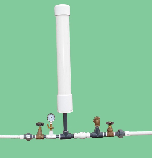
Figure 1. A 3/4-inch homemade hydraulic ram pump made with PVC fittings. Water flows from right to left during operation. Image credit: W. Bryan Smith, Clemson University.
One possible solution to providing livestock drinking water in remote locations is the hydraulic ram pump. The first development work of the hydraulic ram is reported to have been completed by John Whitehurst in 1772, with the first automatic version of the hydraulic ram developed by Joseph Montgolfier in 1796.1 Various companies in England and the United States have been producing cast-iron versions of the hydraulic ram since the early 1800s. Hydraulic ram pumps can lift water over a considerable elevation, and do not require any external power source.
Commercially sold hydraulic ram pumps last for decades but are quite expensive. A simple, homemade PVC (polyvinyl chloride) hydraulic ram pump (figure 1) may be constructed for $150 to $200 depending on material costs in your area and size of pump constructed. These homemade pumps will last for several years if not longer and can allow a farmer to see how such a pump would work before investing in a more expensive commercial unit.
Hydraulic ram pumps operate by utilizing pressure developed by a “water hammer” shock wave. Any object in motion has an in


 8613371530291