
what type of hydraulic pump is most efficient in stock
The goal of a hydraulic pump is to move hydraulic fluid through a hydraulic system, acting much like the beating heart of the system. There are two things that all hydraulic pumps have in common: (1) they provide hydraulic flow to other components (e.g., rams, hydraulic motors, cylinder) within a hydraulic system, and (2) they produce flow which in turn generates pressure when there is a resistance to flow. In addition, most hydraulic pumps are motor-driven and include a pressure relief valve as a type of overpressure protection. The three most common types of hydraulic pumps currently in use are gear, piston, and vane pumps.
In a gear pump, hydraulic fluid is trapped between the body of the pump and the areas between the teeth of the pump’s two meshing gears. The driveshaft is used to power one gear while the other remains idle until it meshes with the driving gear. These pumps are what is known as fixed displacement or positive displacement because each rotation of the shaft displaces the same amount of hydraulic fluid at the same pressure. There are two basic types of gear pumps, external and internal, which will be discussed in a moment.
Gear pumps are compact, making them ideal for applications that involve limited space. They are also simple in design, making them easier to repair and maintain. Note that gear pumps usually exhibit the highest efficiency when running at their maximum speed. In general, external gear pumps can produce higher levels of pressure (up to 3,000 psi) and greater throughput than vane pumps.
External gear pumps are often found in close-coupled designs where the gear pump and the hydraulic motor share the same mounting and the same shaft. In an external gear pump, fluid flow occurs around the outside of a pair of meshed external spur gears. The hydraulic fluid moves between the housing of the pump and the gears to create the alternating suction and discharge needed for fluid flow.
External gear pumps can provide very high pressures (up to 3,000 psi), operate at high speeds (3,000 rpm), and run more quietly than internal gear pumps. When gear pumps are designed to handle even higher pressures and speeds, however, they will be very noisy and there may be special precautions that must be made.
External gear pumps are often used in powerlifting applications, as well as areas where electrical equipment would be either too bulky, inconvenient, or costly. External gear pumps can also be found on some agricultural and construction equipment to power their hydraulic systems.
In an internal gear pump, the meshing action of external and internal gears works with a crescent-shaped sector element to generate fluid flow. The outer gear has teeth pointing inwards and the inner gear has teeth pointing outward. As these gears rotate and come in and out of mesh, they create suction and discharge zones with the sector acting as a barrier between these zones. A gerotor is a special type of internal gear pump that eliminates the need for a sector element by using trochoidal gears to create suction and discharge zones.
Unlike external gear pumps, internal gear pumps are not meant for high-pressure applications; however, they do generate flow with very little pulsation present. They are not as widely used in hydraulics as external gear pumps; however, they are used with lube oils and fuel oils and work well for metering applications.
In a piston pump, reciprocating pistons are used to alternately generate suction and discharge. There are two different ways to categorize piston pumps: whether their piston is axially or radially mounted and whether their displacement is fixed or variable.
Piston pumps can handle higher pressures than gear or vane pumps even with comparable displacements, but they tend to be more expensive in terms of the initial cost. They are also more sensitive to contamination, but following strict hydraulic cleanliness guidelines and filtering any hydraulic fluid added to the system can address most contamination issues.
In an axial piston pump, sometimes called an inline axial pump, the pistons are aligned with the axis of the pump and arranged within a circular cylinder block. On one side of the cylinder block are the inlet and outlet ports, while an angled swashplate lies on the other side. As the cylinder block rotates, the pistons move in and out of the cylinder block, thus creating alternating suction and discharge of hydraulic fluid.
Axial piston pumps are ideal for high-pressure, high-volume applications and can often be found powering mission-critical hydraulic systems such as those of jet aircraft.
In a bent-axis piston pump (which many consider a subtype of the axial piston pump), the pump is made up of two sides that meet at an angle. On one side, the drive shaft turns the cylinder block that contains the pistons which match up to bores on the other side of the pump. As the cylinder block rotates, the distances between the pistons and the valving surface vary, thus achieving the necessary suction and discharge.
In a radial piston pump, the pistons lie perpendicular to the axis of the pump and are arranged radially like spokes on a wheel around an eccentrically placed cam. When the drive shaft rotates, the cam moves and pushes the spring-loaded pistons inward as it passes them. Each of these pistons has its own inlet and outlet ports that lead to a chamber. Within this chamber are valves that control the release and intake of hydraulic fluid.
In a fixed displacement pump, the amount of fluid discharged in each reciprocation is the same volume. However, in a variable displacement pump, a change to the angle of the adjustable swashplate can increase or reduce the volume of fluid discharged. This design allows you to vary system speed without having to change engine speed.
When the input shaft of a vane pump rotates, rigid vanes mounted on an eccentric rotor pick up hydraulic fluid and transport it to the outlet of the pump. The area between the vanes increases on the inlet side as hydraulic fluid is drawn inside the pump and decreases on the outlet side to expel the hydraulic fluid through the output port. Vane pumps can be either fixed or variable displacement, as discussed for piston pumps.
Vane pumps are used in utility vehicles (such as those with aerial ladders or buckets) but are not as common today, having been replaced by gear pumps. This does not mean, however, that they are not still in use. They are not designed to handle high pressures but they can generate a good vacuum and even run dry for short periods of time.
There are other key aspects to choosing the right hydraulic pump that goes beyond deciding what type is best adapted to your application. These pump characteristics include the following:
Selecting a pump can be very challenging, but a good place to start is looking at the type of pump that you need. Vane pumps have been largely replaced by compact, durable gear pumps, with external gear pumps working best for high pressure and operating speeds while internal gear pumps are able to generate flow with very little pulsation. However, vane pumps are still good for creating an effective vacuum and can run even when dry for short periods of time. Piston pumps in general are more powerful but, at the same time, more susceptible to contamination.
Whether the pump is needed for the rugged world of mining, the sterile world of food and beverage processing, or the mission-critical aerospace industry, MAC Hydraulics can assist you with selecting, installing, maintaining, and repairing the right pump to meet the needs of your hydraulic system. In the event of a breakdown, our highly skilled technicians can troubleshoot and repair your pump — no matter who the manufacturer happens to be. We also offer on-site services that include common repairs, preventative maintenance, lubrication, cleaning, pressure testing, and setting.

The type of pump you choose for your power unit affects the nature of the HPU build. Pump choice boils down to cost, complexity and performance. There are three major types of pumps: the gear pump, the vane pump and the piston pump. There are other, less common pumps, but we’ll stick to these three for this discussion.
Gear pumps are economical, but on the low end of the efficiency range. They’re reliable and durable, but efficiency tends to drop over time. Remember, a pump’s job is to convert incoming mechanical energy into hydraulic energy, and the more efficiently it does so not only allows you to choose a smaller motor, but more efficiency saves you money over time. Traditional spur gear pumps average about 80% efficiency, meaning your 10 input horsepower will net you 8 hydraulic horsepower.
Vane pumps reside in the middle ground between gear and piston pumps. They’re more efficient than gear pumps, but less so than piston pumps. Vane pumps are quiet, making them popular for industrial applications. They’re also available with myriad control options, such as pressure compensation, load sensing and displacement control. Vane pumps typically cannot handle high-pressure circuits, however.
Piston pumps take up the premium end of the range. They’re capable of very high pressure, and have nearly infinite methods of control, including pressure compensation, load sensing, servo control, horsepower control, etc. They’re also very efficient; some designs are capable of 95% efficiency, allowing you to get the most from your prime mover. Their downside is cost, both for initial investment, and for service and repair.
Gear pumps have very few moving parts. They consist of two intermeshing gears. These pumps have a constant flow rate. They operate at pressures generally between 50 and 210 bar. Gear pumps operate at the highest speeds of any pumps at up to 3000-6000 rpm.
In an external-gear pump, only one of the gear wheels, the drive gear, is connected to the drive. The other gear wheel, the driven gear, rotates in the opposite direction, so that the teeth of the rotating gear wheels interlock.
There are also double external-gear pumps, which combine two gear pumps driven by the same coupling shaft. A double external-gear pump has the advantage of supplying two independent hydraulic circuits, and also provides more flow to one circuit.
This website is using a security service to protect itself from online attacks. The action you just performed triggered the security solution. There are several actions that could trigger this block including submitting a certain word or phrase, a SQL command or malformed data.

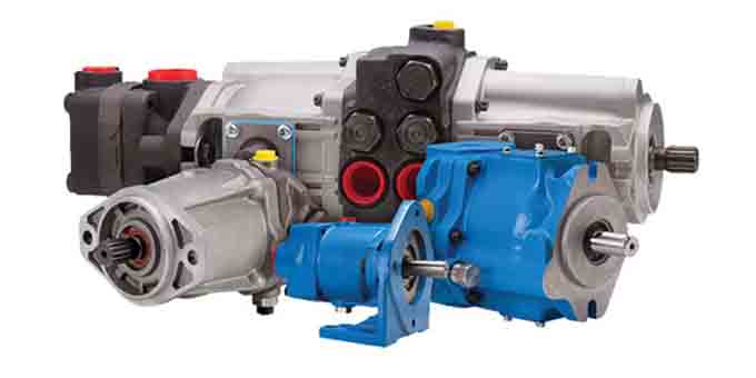
There are typically three types of hydraulic pump constructions found in mobile hydraulic applications. These include gear, piston, and vane; however, there are also clutch pumps, dump pumps, and pumps for refuse vehicles such as dry valve pumps and Muncie Power Products’ Live PakTM.
The hydraulic pump is the component of the hydraulic system that takes mechanical energy and converts it into fluid energy in the form of oil flow. This mechanical energy is taken from what is called the prime mover (a turning force) such as the power take-off or directly from the truck engine.
With each hydraulic pump, the pump will be of either a uni-rotational or bi-rotational design. As its name implies, a uni-rotational pump is designed to operate in one direction of shaft rotation. On the other hand, a bi-rotational pump has the ability to operate in either direction.
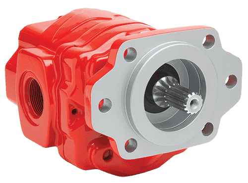
For truck-mounted hydraulic systems, the most common design in use is the gear pump. This design is characterized as having fewer moving parts, being easy to service, more tolerant of contamination than other designs and relatively inexpensive. Gear pumps are fixed displacement, also called positive displacement, pumps. This means the same volume of flow is produced with each rotation of the pump’s shaft. Gear pumps are rated in terms of the pump’s maximum pressure rating, cubic inch displacement and maximum input speed limitation.
Generally, gear pumps are used in open center hydraulic systems. Gear pumps trap oil in the areas between the teeth of the pump’s two gears and the body of the pump, transport it around the circumference of the gear cavity and then force it through the outlet port as the gears mesh. Behind the brass alloy thrust plates, or wear plates, a small amount of pressurized oil pushes the plates tightly against the gear ends to improve pump efficiency.
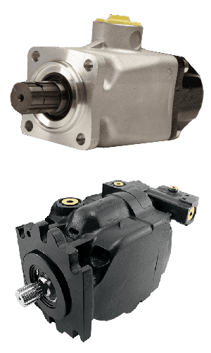
A cylinder block containing pistons that move in and out is housed within a piston pump. It’s the movement of these pistons that draw oil from the supply port and then force it through the outlet. The angle of the swash plate, which the slipper end of the piston rides against, determines the length of the piston’s stroke. While the swash plate remains stationary, the cylinder block, encompassing the pistons, rotates with the pump’s input shaft. The pump displacement is then determined by the total volume of the pump’s cylinders. Fixed and variable displacement designs are both available.
With a fixed displacement piston pump, the swash plate is nonadjustable. Its proportional output flow to input shaft speed is like that of a gear pump and like a gear pump, the fixed displacement piston pump is used within open center hydraulic systems.
As previously mentioned, piston pumps are also used within applications like snow and ice control where it may be desirable to vary system flow without varying engine speed. This is where the variable displacement piston pump comes into play – when the hydraulic flow requirements will vary based on operating conditions. Unlike the fixed displacement design, the swash plate is not fixed and its angle can be adjusted by a pressure signal from the directional valve via a compensator.
Flow and Pressure Compensated Combined – These systems with flow and pressure compensation combined are often called a load-sensing system, which is common for snow and ice control vehicles.
Vane pumps were, at one time, commonly used on utility vehicles such as aerial buckets and ladders. Today, the vane pump is not commonly found on these mobile (truck-mounted) hydraulic systems as gear pumps are more widely accepted and available.
Within a vane pump, as the input shaft rotates it causes oil to be picked up between the vanes of the pump which is then transported to the pump’s outlet side. This is similar to how gear pumps work, but there is one set of vanes – versus a pair of gears – on a rotating cartridge in the pump housing. As the area between the vanes decreases on the outlet side and increases on the inlet side of the pump, oil is drawn in through the supply port and expelled through the outlet as the vane cartridge rotates due to the change in area.
Input shaft rotates, causing oil to be picked up between the vanes of the pump which is then transported to pump outlet side as area between vanes decreases on outlet side and increases on inlet side to draw oil through supply port and expel though outlet as vane cartridge rotates
A clutch pump is a small displacement gear pump equipped with a belt-driven, electromagnetic clutch, much like that found on a car’s air conditioner compressor. It is engaged when the operator turns on a switch inside the truck cab. Clutch pumps are frequently used where a transmission power take-off aperture is not provided or is not easily accessible. Common applications include aerial bucket trucks, wreckers and hay spikes. As a general rule clutch pumps cannot be used where pump output flows are in excess of 15 GPM as the engine drive belt is subject to slipping under higher loads.
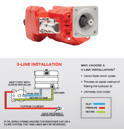
What separates this pump from the traditional gear pump is its built-in pressure relief assembly and an integral three-position, three-way directional control valve. The dump pump is unsuited for continuous-duty applications because of its narrow, internal paths and the subsequent likelihood of excessive heat generation.
Dump pumps are often direct mounted to the power take-off; however, it is vital that the direct-coupled pumps be rigidly supported with an installer-supplied bracket to the transmission case with the pump’s weight at 70 lbs. With a dump pump, either a two- or three-line installation must be selected (two-line and three-line refer to the number of hoses used to plumb the pump); however, a dump pump can easily be converted from a two- to three-line installation. This is accomplished by inserting an inexpensive sleeve into the pump’s inlet port and uncapping the return port.
Many dump bodies can function adequately with a two-line installation if not left operating too long in neutral. When left operating in neutral for too long however, the most common dump pump failure occurs due to high temperatures. To prevent this failure, a three-line installation can be selected – which also provides additional benefits.
Pumps for refuse equipment include both dry valve and Live Pak pumps. Both conserve fuel while in the OFF mode, but have the ability to provide full flow when work is required. While both have designs based on that of standard gear pumps, the dry valve and Like Pak pumps incorporate additional, special valving.
Primarily used on refuse equipment, dry valve pumps are large displacement, front crankshaft-driven pumps. The dry valve pump encompasses a plunger-type valve in the pump inlet port. This special plunger-type valve restricts flow in the OFF mode and allows full flow in the ON mode. As a result, the horsepower draw is lowered, which saves fuel when the hydraulic system is not in use.
In the closed position, the dry valve allows just enough oil to pass through to maintain lubrication of the pump. This oil is then returned to the reservoir through a bleed valve and small return line. A bleed valve that is fully functioning is critical to the life of this type of pump, as pump failure induced by cavitation will result if the bleed valve becomes clogged by contaminates. Muncie Power Products also offer a butterfly-style dry valve, which eliminates the bleed valve requirement and allows for improved system efficiency.
It’s important to note that with the dry valve, wear plates and shaft seals differ from standard gear pumps. Trying to fit a standard gear pump to a dry valve likely will result in premature pump failure.
Encompasses plunger-type valve in the pump inlet port restricting flow in OFF mode, but allows full flow in ON mode lowering horsepower draw to save fuel when not in use
Wear plates and shaft seals differ from standard gear pumps – trying to fit standard gear pump to dry valve likely will result in premature pump failure
Live Pak pumps are also primarily used on refuse equipment and are engine crankshaft driven; however, the inlet on a Live Pak pump is not outfitted with a shut-off valve. With a Live Pak pump, the outlet incorporates a flow limiting valve. This is called a Live Pak valve. The valve acts as an unloading valve in OFF mode and a flow limiting valve in the ON mode. As a result, the hydraulic system speed is limited to keep within safe operating parameters.
Outlet incorporates flow limiting valve called Live Pak valve – acts as an unloading valve in OFF mode and flow limiting valve in ON mode restricting hydraulic system speed to keep within safe operating parameters

One of the fundamental aspects needing to be considered by industrial machinery designers is that of the most suitable type of hydraulic pump to employ. The choice is not an easy one because there are numerous applicable technologies and each one of them is characterized by strengths and weaknesses which have to be carefully weighed up in view of the specific application being addressed. In some cases, the main factor to be considered in the engineering design process may be that of low noise emissions, while in other cases, the need to reduce energy costs could be a key determinant. On the other hand, there may be other instances in which it is essential to use hydraulic pumps with the capacity to manage high levels of pressure and flow rates with an elevated volumetric efficiency, while in some systems of relatively minor complexity, the only really important factor is that of choosing a more economical pump.
The choice of the right hydraulic pump is therefore a decisive one, also in the light of the fact that technology has evolved rapidly and offers many more efficient alternatives to the devices that some designers continue to use for the development of their systems, more frequently out of habit or owing to a certain mistrust towards more recent and innovative technologies.
Interfluid is much more than a mere distributor offering a wide selection of premium hydraulic pumps which have been produced and fine-tuned by international constructors, since it also has the necessary expertise to collaborate in the engineering design process, and recommend the most suitable components for each application. In brief, a sort of “system integrator” of hydraulic pumps. All the hydraulic pumps are assembled and tested by our own specialized staff thanks to the test bench we have set up to guarantee the highest quality standards our clients are accustomed to.
For practical purposes, all pumps fall into one of two large categories: fixed displacement and variable displacement pumps. Starting from the latter, it must be said that variable displacement pump technology has been surpassed in many cases by other systems: while it used to represent the quintessential “energy saving” solution, the introduction of the variable-speed pump and other systems in which hydraulic pumps are combined with electronic systems (such as inverters) have in fact forced this technology to take a back seat in many applications.
The main difference between fixed displacement pumps and those with variable displacement is that the former deliver constant flow rate and pressure while the latter enable energy cost savings when the system does not require capacity thanks to the reciprocation of the flow rate when the system is at peak pressure.
.Deriving from certain fixed displacement pumps, these devices benefit from construction features which are able to vary the flow rate dynamically. The most widely known variable displacement hydraulic pumps are piston pumps and vane pumps
Axial piston pumps with open circuits are designed to handle large flows at high hydraulic system pressures. Typical applications are mobile equipment, hydraulic systems and hydraulic presses, metal forming machinery and concrete injection machines. The main characteristics of piston pumps can be summarized as follows: compact dimensions, high power density, volumetric efficiency and a wide range of regulators, high speed and torque, high operating pressures.
For almost 12 years, Interfluid has made significant investments in the Hydraut brand, which is now one of the most important European constructors of hydraulic pumps operating on international markets. Our product portfolio comprises open-circuit axial piston pumps of the HSP and PQ series, supplied with an 18 month warranty.
Their perfect interchangeability with A10V(S)O pumps and with their relative spare parts has made the series HSP very popular with producers of hydraulic systems, hydraulic repairers and maintenance operators. Instead, the series Hydraut PQ is destined for applications in which it is necessary to use variable displacement piston pumps with operating pressures up to 250 bar coupled with small flows. Their added value consists in low noise levels, compact dimensions and a relatively low price.
Thanks to the know-how and experience Interfluid has built up in the field of variable displacement axial piston pumps, three years ago another new partner joined our team: Kawasaki, which has entrusted to Interfluid the marketing of the series K3VL Eco Servo of reciprocating pumps for combining with energy-saving systems. These pumps are therefore of great interest to all those machinery constructors for whom optimized productivity and the consequential reduced impact on energy consumption is a priority.
Finally, the range offered by Interfluid also includes the series PVPC-PERS of variable displacement axial piston pumps with proportional P/Q control produced by Atos, a brand leader in the production of electro hydraulic systems and components.
The portfolio of variable displacement pumps distributed by Interfluid also comprises the vane pumps Berarma, supplied with ISO e SAE connections and already compatible for combined use with similar or other types of pumps.
Now, let’s take a closer look at fixed displacement pumps which, in their turn, may also be classified as follows, according to the type of construction technology: vane pumps, internal gear pumps, external gear pumps and helical gear pumps.They are employed in various hydraulic solutions, from the more traditional and simple types to today’s latest energy-saving solutions.
Let’s start with vane pumps, devices that are generally used in cases when the operating pressure and flow rate are not very high or when the volumetric efficiency required at high pressures is not particularly elevated. They offer the advantage of being easy to handle, since it is quite a simple operation to change the displacement and create systems with single, double or triple pumps. For more than 20 years, Interfluid has been the unquestioned leader in this segment, being able to count on a time-consolidated experience, a well equipped workshop to ensure rapid order processing and shipment, a high level of assembly flexibility and an accurate quality control system.
The go-to brand is certainly Veljan, a company which has specialized in the construction of vane pumps since 1970 and has belonged to the Hagglunds and Denison Group for almost 30 years. The sound reliability and wide range of vane pumps Veljan offers make it one of the top producers on the international market. Interfluid stocks hundreds of hydraulic vane pumps and motors in the company warehouse and this enables us to ship most orders within a few days. All Veljan VT6 and VT7 pumps and their respective spare parts are perfectly compatible with Parker Denison.
To complete the range, Interfluid markets the pumps of the Atos series PFE and the Hydraut medium pressure vane pumps of the series HS, HQ and VH which are perfectly interchangeable with Vickers, spare parts comprised.
The differences between these brands in terms of range, that is to say size, displacement, operating pressure and interchangeability, enable Interfluid to offer customers an extremely wide range of solutions in terms of technical solutions and price.
While fixed displacement vane pumps represent the most conventional solution, internal gear pumps are the natural alternative when having to construct systems that require more elevated operating pressures, a need that is arising more and more frequently, with a view to an all-round optimization of machinery in terms of cost. Thanks to their remarkable construction technology, they enable greater volumetric efficiencywhen compared to vane pumps. With regard to the question of energy savings, an increasingly topical issue in industry, the internal gear pump is the ideal component for creating a system with the capacity to increase the overall performance of the machines and, when coupled with the right inverter, enable a considerable saving in energy costs as well.
This type of hydraulic pump is mainly used at present in the plastic and rubber injection industry, but is starting to be employed also in die casting and, more generally, in hydraulic systems where a reduced level of noise is essential. One of the advantages internal gear pumps have over other pumps with different construction technologies is in fact a significantly reduced level of noise emissions. Therefore, this aspect is very important in manufacturing companies employing many machines in the same department where noise emissions represent a critical issue that needs to be addressed.
With a ten-year experience in internal gear pump technology, Interfluid has many contacts in the ambit of press production destined for plastic, rubber, wood and metalworking, and has recently signed a trade agreement with Bucher, a leading company in the industry, combined with investments in know-how and product stock for the purpose of providing an efficient service to its customers. The core products of the German company are the new QXEH and QXEHX series, pumps designed to be employed in the ambit of variable speed systems, thanks to the use of inverters and synchronous motors. Interfluid also distributes the pumps of the QXM and QXEM series, four-quadrant internal gear pumps, which are ideal for energy-saving closed-circuit operations enabling the elimination of flow control valves (on/off and proportional) and which may also be used as motors for energy recovery purposes.
The choice of internal gear pumps offered by Interfluid includes Hydraut HG pumps that can be a valid solution in the sectors of plastic and rubber injection molding, machine tools, trimming presses, press brakes, die casting and for the construction of hydraulic power units.
It is also worth mentioning the external gear pumps traditionally used in relatively simple systems and in those cases in which high performance is not required in terms of pressure and volumetric efficiency. The principal advantage offered by this type of hydraulic pump is that it is more competitively priced than other types of pumps, while its main disadvantage is certainly represented by a higher level of noise emissions.
Since 2019, Interfluid has also been the authorized distributor for Marzocchi with which it has an agreement for the distribution of various hydraulic components, comprising the external gear pumps ALP and GHP.
An interesting alternative to conventional external gear pumps is provided by Elika helical gear pumps which Marzocchi has recently designed to make up for the two major defects associated with traditional external gear pumps: elevated noise emissions and low volumetric efficiency. In terms of technology and performance, this product is positioned midway between external gear pumps and internal gear pumps, and therefore offers a fair compromise between cost and performance.

In a condition-based maintenance environment, the decision to change out a hydraulic pump or motor is usually based on remaining bearing life or deteriorating efficiency, whichever occurs first.
Despite recent advances in predictive maintenance technologies, the maintenance professional’s ability to determine the remaining bearing life of a pump or motor, with a high degree of accuracy, remains elusive.
Deteriorating efficiency on the other hand is easy to detect, because it typically shows itself through increased cycle times. In other words, the machine slows down. When this occurs, quantification of the efficiency loss isn’t always necessary. If the machine slows to the point where its cycle time is unacceptably slow, the pump or motor is replaced. End of story.
In certain situations, however, it can be helpful, even necessary, to quantify the pump or motor’s actual efficiency and compare it to the component’s native efficiency. For this, an understanding of hydraulic pump and motor efficiency ratings is essential.
There are three categories of efficiency used to describe hydraulic pumps (and motors): volumetric efficiency, mechanical/hydraulic efficiency and overall efficiency.
Volumetric efficiency is determined by dividing the actual flow delivered by a pump at a given pressure by its theoretical flow. Theoreticalflow is calculated by multiplying the pump’s displacement per revolution by its driven speed. So if the pump has a displacement of 100 cc/rev and is being driven at 1000 RPM, its theoretical flow is 100 liters/minute.
Actualflow has to be measured using a flow meter. If when tested, the above pump had an actual flow of 90 liters/minute at 207 bar (3000 PSI), we can say the pump has a volumetric efficiency of 90% at 207 bar (90 / 100 x 100 = 90%).
Its volumetric efficiency used most in the field to determine the condition of a hydraulic pump - based on its increase in internal leakage through wear or damage. But without reference to theoretical flow, the actual flow measured by the flow meter would be meaningless.
A pump’s mechanical/hydraulic efficiency is determined by dividing thetheoretical torque required to drive it by the actual torque required to drive it. A mechanical/hydraulic efficiency of 100 percent would mean if the pump was delivering flow at zero pressure, no force or torque would be required to drive it. Intuitively, we know this is not possible, due to mechanical and fluid friction.
Table 1. The typical overall efficiencies of hydraulic pumps, as shown above, are simply the product of volumetric and mechanical/hydraulic efficiency.Source: Bosch Rexroth
Like theoretical flow, theoretical drive torque can be calculated. For the above pump, in SI units: 100 cc/rev x 207 bar / 20 x p = 329 Newton meters. But like actual flow, actual drive torque must be measured and this requires the use of a dynamometer. Not something we can - or need - to do in the field. For the purposes of this example though, assume the actual drive torque was 360 Nm. Mechanical efficiency would be 91% (329 / 360 x 100 = 91%).
Overall efficiency is simply the product of volumetric and mechanical/hydraulic efficiency. Continuing with the above example, the overall efficiency of the pump is 0.9 x 0.91 x 100 = 82%. Typical overall efficiencies for different types of hydraulic pumps are shown in the Table 1.
System designers use the pump manufacturers’ volumetric efficiency value to calculate the actual flow a pump of a given displacement, operating at a particular pressure, will deliver.
As already mentioned, volumetric efficiency is used in the field to assess the condition of a pump, based on the increase in internal leakage due to wear or damage.
When calculating volumetric efficiency based on actual flow testing, it’s important to be aware that the various leakage paths within the pump are usually constant. This means if pump flow is tested at less than full displacement (or maximum RPM) this will skew the calculated efficiency - unless leakage is treated as a constant and a necessary adjustment made.
For example, consider a variable displacement pump with a maximum flow rate of 100 liters/minute. If it was flow tested at full displacement and the measured flow rate was 90 liters/minute, the calculated volumetric efficiency would be 90 percent (90/100 x 100). But if the same pump was flow tested at the same pressure and oil temperature but at half displacement (50 L/min), the leakage losses would still be 10 liters/minute, and so the calculated volumetric efficiency would be 80 percent (40/50 x 100).
The second calculation is not actually wrong, but it requires qualification: this pump is 80 percent efficient at half displacement. Because the leakage losses of 10 liters/minute are nearly constant, the same pump tested under the same conditions will be 90 percent efficient at 100 percent displacement (100 L/min) - and 0 percent efficient at 10 percent displacement (10 L/min).
To help understand why pump leakage at a given pressure and temperature is virtually constant, think of the various leakage paths as fixed orifices. The rate of flow through an orifice is dependant on the diameter (and shape) of the orifice, the pressure drop across it and fluid viscosity. This means that if these variables remain constant, the rate of internal leakage remains constant, independent of the pump"s displacement or shaft speed.
Overall efficiency is used to calculate the drive power required by a pump at a given flow and pressure. For example, using the overall efficiencies from the table above, let us calculate the required drive power for an external gear pump and a bent axis piston pump at a flow of 90 liters/minute at 207 bar:
As you’d expect, the more efficient pump requires less drive power for the same output flow and pressure. With a little more math, we can quickly calculate the heat load of each pump:
No surprise that a system with gear pumps and motors requires a bigger heat exchanger than an equivalent (all other things equal) system comprising piston pumps and motors.
Brendan Casey has more than 20 years experience in the maintenance, repair and overhaul of mobile and industrial equipment. For more information on reducing the operating cost and increasing the...

The hydraulic pumps found in virtually all mobile and industrial applications today use pistons, vanes, or gears to create the pumping action that produces flow. Each method features individual characteristics that differentiate it from the others and make it suitable for a particular range of applications.
Piston pumps can have the pistons arranged in a radial or axial fashion. Radial types tend to be specialized for applications requiring very high power, while axial piston pumps are available in a wide range of displacements and pressure capabilities that make them suitable for many mobile and industrial tasks.
Axial-piston pumps consist of a set of pistons that are fitted within a cylinder block and driven by an angled swash plate powered by the input shaft. As the swash plate rotates, the pistons reciprocate in their respective cylinder block bores to provide the pumping action. (Figure 1 above)
Axial-piston pumps are available with the input shaft and pistons arranged coaxially, or with the input shaft mounted at an angle to the piston bores. Bent axis pumps tend to be slightly more volumetrically efficient for technical reasons, but they also tend to be slightly larger for a given capacity and their shape can present packaging difficulties in some applications.
A unique characteristic of a piston-type pump is that the displacement can be changed simply by changing the angle of the swash plate. Any displacement between zero and maximum is easily achieved with relatively simple actuators to change the swash plate angle.
The most commonly encountered vane-type pump generates flow using a set of vanes, which are free to move radially within a slotted rotor that rotates in an elliptical chamber. A typical configuration uses an elliptical cam ring with the rotor spinning within in a cylindrical housing and a pair of side plates to form the pumping chambers. (Figure 2) The changing volume of the cavity between adjacent vanes creates the pumping action as the rotor rotates.
It is possible to vary the displacement of a vane-type pump, but this is not commonly done except for very specialized applications. The majority of the vane-type pumps used in industrial and mobile applications have a fixed displacement.
Vane pumps can be hydraulically balanced, which greatly enhances efficiency. Some designs place the rotating group in a cartridge, which makes them very easy to repair. The entire rotating group is easily removed and replaced by simply removing the back cover, pulling out the old rotating cartridge and replacing it with a new one.
The simplest gear-type pump uses a pair of mating gears rotating in an oval chamber to produce flow. As the gears rotate, the changing size of the chambers created by the meshing and unmeshing of the teeth provides the pumping action. (Figure 3)
Another design uses an external rotating ring with internal gear teeth that mesh with an internal gear as it rotates. As the inner gear rotates, the tooth engagement creates chambers of diminishing size between the inlet and outlet positions to create flow.
A more sophisticated variant of this principle is the gerotor pump, which has a non-concentric inner and outer rotor with different numbers of teeth. As the pair rotates, the changing volume of the space between the rotors creates the pumping action. Replacing the meshing teeth of the gerotor pump with low-friction rolling elements produces a geroter pump.
All gear-type pumps have a fixed displacement. These pumps are relatively inexpensive compared to piston and vane type pumps with similar displacements, but tend to wear out more quickly and are not generally economically repairable.
Piston-type pumps have a very good service life, provided contamination and heat are controlled. They also have the highest pressure ratings, and the significant advantage of variable displacement. This makes them the best choice for applications where high efficiency and high power density are important considerations. The ability to configure piston-type pumps with both pressure sensing and load sensing capabilities is an important advantage, particularly in mobile applications.
Vane-type pumps are widely used in constant flow/constant pressure industrial applications because they are quiet and easily repaired. They also have the unique attribute of allowing a “soft start” because vane-type pumps typically do not achieve full output at speeds below about 600 rpm. This characteristic can significantly reduce the starting current requirements of electric motors driving a vane-type pump which extends motor life.
Gear pumps are very common in constant flow/constant pressure applications on mobile equipment because of their low cost and dirt tolerance. They are also widely used as charge pumps to pressurize the inlets of piston and vane pumps because of their excellent inlet vacuum tolerance.
Sizing a pump is not really dependent on which technology is chosen. In all cases, it is best to start with the load and then work back through the system calculating losses at each point. Once the theoretical pressure and flow characteristics are calculated, the input horsepower requirement can be determined. A 20% safety factor is commonly used in determining the pump input horsepower requirement to account for efficiency losses in the pump.
Mobile applications that may encounter overrunning loads often require special valve plates that alter the stroke of a piston pump more quickly than standard units. Such proper valving reduces the internal forces in the pump allowing it to come out of stroke more quickly to respond to the load condition.
You should also be aware that many pump options often are not listed in manufacturer’s catalog literature. It is always a good policy to consult with the pump manufacturer or your local representative when sizing or selecting a pump for a specific application.
Today’s hydraulic pumps are sophisticated, precision products that will enhance the customer value of the equipment they power. Knowing the characteristics of each of the common pump technologies and selecting the units that deliver the best balance of cost versus performance in your application is the best way to maximize that value.
Piston pumps have the highest pressure capabilities of the three technologies, up to 7250 psi (500 bar) for those in common use, and as high at 10,000 psi (690 bar) for certain specialized units. Vane and gear pumps are commonly limited to pressures up to about 4000 psi (275 bar).
Hydraulic power density is directly related to operating pressure; the higher the pressure the greater the power density. Piston pumps offer the highest power density with vane and gear types following in that order.
Like power density, the conversion ratio of input power to output power is directly related to operating pressure. Piston pumps offer the highest conversion ratio, followed by vane and gear pumps in that order. The ability of piston and vane pumps to be hydraulically balanced is also a factor in their greater conversion efficiency.
No hydraulic component is immune to damage from dirt! But of the three pump technologies, the gear-type is the most dirt tolerant, followed by vane and piston pumps in that order.
Positive inlet pressure is always preferred in hydraulic pump applications to avoid wear and premature failure. However, of the three technologies, gear-type pumps are the most vacuum tolerant handling vacuums up to 10 in.-Hg (254 mm-Hg). Vane-type pumps can handle inlet vacuum up to 6 in.-Hg (152.4 mm-Hg) and piston-type pumps up to 4 in.-Hg (101.6 mm-Hg).
It is worth noting that piston pumps can be significantly quieted by altering the metering notch geometry on the valve plate. Doing so, however, reduces their efficiency. There is no free lunch.
Gear pumps tend to the lightest for a given displacement, followed by vane and piston pumps in that order. Note also that all three types can be “ganged” by stacking multiple sections together. This is more commonly done with gear and vane pumps, but double piston pumps are also available.
Piston and gear pumps tend to offer the greatest range of fluid compatibilities. Note that is it often necessary to de-rate a pump when it is used with non-petroleum fluids.
Fluid compatibility depends on the type of seals, O-rings and materials used in the construction of a pump. It’s best to consult the manufacturer before using any alternative fluids.
Some of our calculators and applications let you save application data to your local computer. These applications will - due to browser restrictions - send data between your browser and our server. We don"t save this data.
Google use cookies for serving our ads and handling visitor statistics. Please read Google Privacy & Terms for more information about how you can control adserving and the information collected.

Hydraulic pumps come in different forms to accommodate a range of application requirements, from industrial die presses to heavy-duty off road equipment. One hydraulic system can vary greatly from another. For one system, a hydraulic piston pump may be the best solution, while a hydraulic gear pump may be better suited for a different one.
Powered by a hydraulic drive, a piston pump has a reciprocating positive displacement design to manage fluid flow. Pistons, or cylindrical elements within a cylinder block, create a vacuum, generated by a drive mechanism, that draws in fluid. The cylindrical chamber is pressurised by distributing energy into the fluid, compressing and forcing it towards the pump’s outlet.
Basic designs can generate about 4,000 psi, but pumps with up to 14,500 psi operating pressure are available. There are many different models that can displace a specific amount of fluid. Some allow you to adjust the displacement per revolution, which can make them more energy efficient. Piston pumps are relatively complex in design and expensive, but practical in energy-efficient applications that require high pressures and effective oil flow control.
A hydraulic gear pump is a lower-cost option, but it is quite durable, with many options available. The typical pressure rating is about 3,000 psi, but many displacement sizes and pressures can be found. Some gear pumps are rated as high as 4,500 psi, although additional valves will be needed in systems that require regular flow adjustments.
Gear pumps function by drawing fluid between their meshing gears. The adjacent gear teeth form chambers that are enclosed within the housing and pressure plates. A partial vacuum forms at the inlet where the gear teeth unmesh, allowing fluid to fill the space and be moved along the outer edge of the gears; as the gear teeth mesh again, fluid is forced out of the pump.
Both pumps use hydraulic fluid to transfer energy or generate mechanical force. Hydraulic piston pumps rely on reciprocating motion. Rotational forces are generated along an axis. Fixed and variable displacement pumps are available, as are different types, including axial, inline, bent-axis, plunger, and radial pumps, each with its own unique method of pushing fluid.
On the other hand, gear pumps move fluid via tightly aligned cogs that create suction to draw in and discharge fluid. Pumps with internal or external gears can be used, depending on the application requirements. Lobe, screw, and vane pumps are just some available types. A downside of using gear pumps is that additional devices are needed to control the desired amount of displacement, as they operate on fixed displacement only.
While gear pumps are available in a wide range of displacement sizes and pressures, and they suit various machinery applications, piston pumps offer the benefits of higher pressure ratings and are variable displacement and energy efficient. Rapid cooling means each pump is ready for the next operating cycle and can be serviced soon after shut-off.
Gear pumps typically don’t move more than 50 gallons per minute of fluid. On the other hand, some piston pumps can move hundreds of gallons per minute. Either one has advantages, depending on your hydraulic application.
Hydraulic pumps are available in different types, sizes, pressure ratings, and other specifications. It is important to choose the right pump for your hydraulic system. Gear pumps are suited for various types of machinery. Piston pumps are often found in oil field and agricultural applications, as well as in heavy-duty construction equipment. They are reliable and efficient, and they resist leakage at high speeds and pressures.
White House Products, Ltd. supplies, repairs, and maintains hydraulic gear pumps and hydraulic piston pumps from leading manufacturers. We can assist you in choosing a pump that meets your application requirements. Start browsing our catalog or register/login to view prices/availability and place an order. Contact us at +44 (0)1475 742500 for more information.

Hydraulics are essential in many industrial applications; they use mechanical energy to force liquid into a system. Within the category of hydraulics, there are many different types of hydraulic pumps that accomplish various tasks within industrial fields. Let’s take a look at some of them.
An axial piston hydraulic pump is also a positive displacement pump. Axion pumps have cylinders that are assembled around a central axis (cylinder block). Within each cylinder, there are pistons which will attach to a swashplate or wobble plate. These swashplates then connect to the rotating shaft, which moves the pistons and pulls them in and out of the cylinders.
Axial piston pumps can also be made into variable displacement piston pumps, which provide more control over speed. In variable pumps, the swashplate is used to set the depth of the pistons, which creates a length variation to affect the discharge volume. This design helps maintain constant discharge rates in industrial applications.
Another hydraulic pump type is the radial piston pump. As the name suggests, the pistons are arranged along the radius of the cylindrical block, which includes the pintle and rotor. The rotor powers the pistons through the cylinders and forces hydraulic fluid in and out of the cylinder.
Both axial and radial piston pumps are used for high-operating pressures as they can withstand much higher pressures than hydraulic pump types. They are often used in ice and snow control applications, as well as on truck-mounted cranes.
A rotary vane pump is also a type of positive displacement pump. It uses rigid vanes rather than the rotor hubs. These vanes are placed around an eccentric rotor device, which moves around the inside wall of the housing container. This movement forces the hydraulic fluid through the discharge port, and, in some applications, can be adjusted to align with the rotational axis of the motor.
Vane pumps are often used in utility vehicles but have lost popularity over the years in favor of gear pump hydraulic systems. However, they used to be very common in aerial buckets and ladders along with other mobile, truck-mounted hydraulic applications.
Gear pumps have become the most common hydraulic pump type that’s used in industrial applications today. The gear pump has fewer moving parts than piston or vane pumps, which makes it easy to service and relatively inexpensive compared to other hydraulic pumps. They are also less likely to be contaminated during use.
An external gear pump uses two gears on the outside of individual shafts to aid in movement and push both thin and thick fluids through the gears. These external pumps are commonly used in fixed-displacement applications and high-pressure environments.
Internal gear pumps place gears on the insides of the shafts rather than on the outside as found in external gear pumps. That makes them self-priming and non-pulsing, and can even be run without liquid for short periods of time—although they can’t be left dry for too long.
Additionally, internal gear pumps are bi-rotational, meaning that one can be utilized to both unload and load devices. And, with only two moving parts, they are considered to be one of the most reliable types of hydraulic pumps.
Volumetric efficiency is the amount of output the pump actually produces as a percentage of its theoretical production.The higher the percentage the more efficient the pump.
Among the factors affecting volumetric efficiency are leakage and fluid compressibility (ability for volume to be reduced under pressure). These issues can cause the pump to lose efficiency and waste energy as that energy converts to heat.
Still have questions about hydraulic pumps or their parts and repairs? Contact Panagon Systems today. We’ve been a leading hydraulic pump manufacturer in the U.S. for over two decades, and can help you find the best solution for your application. You can view our full line of pumps here. To request a consultation or quote, please fill out our online form.

The type of hydraulic pump you need depends on a variety of factors, including, but not limited to, the type of hydraulic fluid used in your machinery, operating pressure, application speed, and flow rate requirements.
Two of the most common pumps used in hydraulic equipment are piston pumps and gear pumps. This article will highlight everything you need to know about each pump, including its common uses and benefits.
A piston pump is a positive displacement pump that uses reciprocating motion to create rotation along an axis. Some piston pumps have variable displacement, while others have a fixed displacement design.
A hydraulic piston pump is capable of the highest pressure ratings and is commonly used to power heavy-duty lifts, presses, shovels, and other components.
The downside of piston pumps is that they are often more expensive (especially when compared to gear pumps). Still, their improved efficiency often makes them a better investment for long-term production.
Gear pumps use gears or cogs to transfer fluids. The cogs are tightly aligned to create suction as they draw liquid in and discharge it. The gears can be internal or external, depending on the application. Gear pumps are also positive displacement pumps, but they are always fixed displacement, so you would need separate pumps or valves to control the amount of displacement.
Gear pumps are known for being reliable and durable when they are well-maintained. Compared to piston pumps, they also don’t require as much maintenance and are typically more affordable. However, these pumps usually max out at 3000 PSI. While this is enough pressure to power some machinery, it may not have the power to operate large presses and other industrial equipment. A gear-style pump also lacks the ability to vary the displacement of your system.
Gear pumps are often used in low-pressure applications where dispensing high-viscosity liquids is required. They are typically used in the food and beverage, pulp and paper, and oil/chemical industries.
The primary difference between a gear pump and a piston pump is how they are designed. While both pumps need hydraulic fluid to generate mechanical power, a piston pump uses a piston to move liquid throughout the pump valves, while a gear pump uses cogs to move fluid throughout the pump.
Gear pumps are affordable for low-pressure applications (35 to 200 bar or 507 to 2900 PSI), while piston pumps are more efficient options for high-pressure applications. A piston pump is also a better option if you’re looking for a pump with a higher discharge rate. Lastly, a piston pump will provide the most efficiency if your application is high-speed.
Founded over 25 years ago. Panagon Systems specializes in remanufacturing cost-efficient obsolete or discontinued piston pumps, motors, and replacement components from brands like Vickers/Eaton, Caterpillar, and Rexroth. All pumps we manufacture are made in-house in the United States and are guaranteed to meet OEM specifications.
If you’re looking for cost-effective and timely pump replacement options, you’re looking for us.Contact us todayfor help in selecting the right pump for your application, or to request a product quote.

Although many detractors sneer at the idea of hydraulic efficiency, right-sizingcomponents, proper system design and moderntechnology can go a long way to achieving system efficiency.
“Hydraulic efficiency”is a term alluding similar sentiments to “exact estimate” or “scientific belief.” It’s not that hydraulic efficiency is an oxymoron, per se, but these aren’t traditionally two words that make sense shoulder to shoulder. If efficiency was your top benefit on the list of machine requirements, fluid power wouldn’t have been on your short list of options, at least in the past half-century or longer.
Efficiency is a word now more commonly familiar to us, thanks to the escalation of green values—especially those defining the way we use natural resources. No longer can we take a limitless and inexpensive source of energy for granted, nor can we abuse the dirty sources of inexpensive energy at the expense of our precious environment. We must take full advantage of our energy resources to achieve the work required for maintaining our standard of living, while reducing associated waste along the way.
What is efficiency?I define efficiency as work-in minus work-out. Essentially, it’s the differential between the energy your process requires and the energy input required to achieve that process. Your process could be stamping, rolling, injecting, moving, pressing or any other mechanical function capable of being achieved in a rotational or linear motion. If you’re running a punch press, for example, the machine efficiency is defined as the current draw of the pump’s motor minus the combined force and velocity of the punch die.
Most machines are designed to convert energy from one form to another, which can sometimes occur multiple times. Because of the Laws of Thermodynamics, you cannot change energy from one form to another without creating waste energy, and this is a fact regardless of the energy transformation taking place. In the case of a hydraulic machine, you must convert electrical energy to mechanical energy within the electric motor, resulting in partial waste. Then you must convert mechanical energy into hydraulic energy within the pump, resulting in partial waste. Then you must convert hydraulic energy back into mechanical energy at your cylinder or hydraulic motor, resulting in partial waste.
The amount of energy wasted in the above example could be staggering, especially if you’re using an old machine with old components. Let’s say you have a 10-hp electric motor—and keep in mind electric motors are rated on power consumption, not power output. Your old motor might have an efficiency of 85%, meaning it will produce 8.5 hp at its shaft, the other 1.5 hp being wasted as pure heat.
In your old power unit, you have a worn and tired gear pump. When new, a gear pump is lucky to have 80% efficiency, so I’ll be generous to throw 75% at this example, since gear pumps become less efficient over their lifetimes. So this pump can convert only 6.4 of the motor’s 8.5-hp shaft output into usable hydraulic energy. The rest of the energy


 8613371530291