
what type of hydraulic pump is most efficient made in china

This website is using a security service to protect itself from online attacks. The action you just performed triggered the security solution. There are several actions that could trigger this block including submitting a certain word or phrase, a SQL command or malformed data.

This website is using a security service to protect itself from online attacks. The action you just performed triggered the security solution. There are several actions that could trigger this block including submitting a certain word or phrase, a SQL command or malformed data.
Gear pumps are commonly used for hydraulic fluid power applications in machines like forklifts. With a simple design, they’re a cost-efficient solution that’s easy to use and easy to maintain. Our product range includes both internal and external gear pumps.
An external gear pump has two identical gears that typically turn towards each other. Displacement chambers form between the gear tooth profiles, the internal walls of the housing, and the surfaces of the bearing blocks. The oil is transported from the suction side to the pressure side within these chambers. The flow of a gear pump is fixed per rotation.
An internal gear pump operates in the same way. It has two interlocking gears of different sizes. The larger gear (rotor) is the internal gear. The smaller external gear, also known as the idler, rotates inside the large gear. When the two gears interlock, the liquid is pushed forward under pressure.

The hydraulic power pumps are ideal for small, high-pressure applications. They have a positive lifplacementpan and a variety of hydraulic power pumps, ideal for those who want to save energy on rotating pumps.
The lifespan of the hydraulic pump is good because they can maintain more pressure, and with a higher volume, it don"t need to worry about the lifespan of the hydraulic pump system.
If you are looking for ideal hydraulic pumps, there are a wide range of them, on Alibaba.com. These high-pressure pumps are ideal for hydraulic pumps, such as electric hydraulic pumps, and many other variable pumps. Check out Alibaba.com"s wide range of cheap hydraulic pumps, ideal hydraulic pumps for high-pressure applications, and choose the ones that are ideal for these pumps.
When hydraulic pumps are available, Alibaba.com offers a wide range of hydraulic pumps for sale in different sizes, you can choose from one of the different types of hydraulic pumps for sale.

Hydraulic systems are in general members of the fluid power branch of power transmission. Hydraulic pumps are also members of the hydraulic power pack/hydraulic power unit family. Hydraulic units are encased mechanical systems that use liquids for hydraulics.
The hydraulic systems that hydraulic pumps support exist in a range of industries, among them agriculture, automotive manufacturing, defense contracting, excavation, and industrial manufacturing. Within these industries, machines and applications that rely on hydraulic pumps include airplane flaps, elevators, cranes, automotive lifts, shock absorbers, automotive brakes, garage jacks, off-highway equipment, log splitters, offshore equipment, hydraulic motors/hydraulic pump motors, and a wide range of other hydraulic equipment.
When designing hydraulic pumps, manufacturers have many options from which to choose in terms of material composition. Most commonly, they make the body of the pump–the gears, pistons, and hydraulic cylinders–from a durable metal material. This metal is one that that can hold up against the erosive and potentially corrosive properties of hydraulic fluids, as well as the wear that comes along with continual pumping. Metals like this include, among others, steel, stainless steel, and aluminum.
First, what are operating specifications of their customer? They must make sure that the pump they design matches customer requirements in terms of capabilities. These capabilities include maximum fluid flow, minimum and maximum operating pressure, horsepower, and operating speeds. Also, based on application specifications, some suppliers may choose to include discharge sensors or another means of monitoring the wellbeing of their hydraulic system.
Next, what is the nature of the space in which the pump will work? Based on the answer to this question, manufacturers will design the pump with a specific weight, rod extension capability, diameter, length, and power source.
Manufacturers must also find out what type of substance does the customer plan on running through the pumps. If the application calls for it, manufacturers can recommend operators add other substances to them in order to decrease the corrosive nature of certain hydraulic fluids. Examples of such fluids include esters, butanol, pump oils, glycols, water, or corrosive inhibitors. These substances differ in operating temperature, flash point, and viscosity, so they must be chosen with care.
All hydraulic pumps are composed in the same basic way. First, they have a reservoir, which is the section of the pump that houses stationary fluid. Next, they use hydraulic hoses or tubes to transfer this fluid into the hydraulic cylinder, which is the main body of the hydraulic system. Inside the cylinder, or cylinders, are two hydraulic valves and one or more pistons or gear systems. One valve is located at each end; they are called the intake check/inlet valve and the discharge check/outlet valve, respectively.
Hydraulic pumps operate under the principle of Pascal’s Law, which states the increase in pressure at one point of an enclosed liquid in equilibrium is equally transferred to all other points of said liquid.
To start, the check valve is closed, making it a normally closed (NC) valve. When the check is closed, fluid pressure builds. The piston forces the valves open and closes repeatedly at variable speeds, increasing pressure in the cylinder until it builds up enough to force the fluid through the discharge valve. In this way, the pump delivers sufficient force and energy to the attached equipment or machinery to move the target load.
When the fluid becomes pressurized enough, the piston withdraws long enough to allow the open check valve to create a vacuum that pulls in hydraulic fluid from the reservoir. From the reservoir, the pressurized fluid moves into the cylinder through the inlet. Inside the cylinder, the fluid picks up more force, which it carries over into the hydraulic system, where it is released through the outlet.
Piston pumps create positive displacement and build pressure using pistons. Piston pumps may be further divided into radial piston pumps and axial piston pumps.
Radial pumps are mostly used to power relatively small flows and very high-pressure applications. They use pistons arranged around a floating center shaft or ring, which can be moved by a control lever, causing eccentricity and the potential for both inward and outward movement.
Axial pumps, on the other hand, only allow linear motion. Despite this, they are very popular, being easier and less expensive to produce, as well as more compact in design.
Gear pumps, or hydraulic gear pumps, create pressure not with pistons but with the interlocking of gear teeth. When teeth are meshed together, fluid has to travel around the outside of the gears, where pressure builds.
External gear pumps facilitate flow by enlisting two identical gears that rotate against each other. As liquid flows in, it is trapped by the teeth and forced around them. It sits, stuck in the cavities between the teeth and the casing, until it is so pressurized by the meshing of the gears that it is forced to the outlet port.
Internal gear pumps, on the other hand, use bi-rotational gears. To begin the pressurizing process, gear pumps first pull in liquid via a suction port between the teeth of the exterior gear, called the rotor, and the teeth of the interior gear, called the idler. From here, liquid travels between the teeth, where they are divided within them. The teeth continue to rotate and mesh, both creating locked pockets of liquid and forming a seal between the suction port and the discharge port. Liquid is discharged and power is transported once the pump head is flooded. Internal gears are quite versatile, usable with a wide variety of fluids, not only including fuel oils and solvents, but also thick liquids like chocolate, asphalt, and adhesives.
Various other types of hydraulic pumps include rotary vane pumps, centrifugal pumps, electric hydraulic pumps, hydraulic clutch pumps, hydraulic plunger pumps, hydraulic water pumps, hydraulic ram pumps, portable 12V hydraulic pumps, hydraulic hand pumps, and air hydraulic pumps.
Rotary vane pumps are fairly high efficiency pumps, though they are not considered high pressure pumps. Vane pumps, which are a type of positive-displacement pump, apply constant but adjustable pressure.
Centrifugal pumps use hydrodynamic energy to move fluids. They feature a rotating axis, an impeller, and a casing or diffuser. Most often, operators use them for applications such as petroleum pumping, sewage, petrochemical pumping, and water turbine functioning.
Electric hydraulic pumps are hydraulic pumps powered by an electric motor. Usually, the hydraulic pump and motor work by turning mechanisms like impellers in order to create pressure differentials, which in turn generate fluid movement. Nearly any type of hydraulic pump can be run with electricity. Most often, operators use them with industrial machinery.
Hydraulic clutch pumps help users engage and disengage vehicle clutch systems. They do so by applying the right pressure for coupling or decoupling shafts in the clutch system. Coupled shafts allow drivers to accelerate, while decoupled shafts allow drivers to decelerate or shift gears.
Hydraulic ram pumps are a type of hydraulic pump designed to harness hydropower, or the power of water, to elevate it. Featuring only two moving hydraulic parts, hydraulic ram pumps require only the momentum of water to work. Operators use hydraulic ram pumps to move water in industries like manufacturing, waste management and sewage, engineering, plumbing, and agriculture. While hydraulic ram pumps return only about 10% of the water they receive, they are widely used in developing countries because they do not require fuel or electricity.
Hydraulic water pumps are any hydraulic pumps used to transfer water. Usually, hydraulic water pumps only require a little bit of energy in the beginning, as the movement and weight of water generate a large amount of usable pressure.
Air hydraulic pumps are hydraulic pumps powered by air compressors. In essence, these energy efficient pumps work by converting air pressure into hydraulic pressure.
Hydraulic pumps are useful for many reasons. First, they are simple. Simple machines are always an advantage because they are less likely to break and easier to repair if they do. Second, because fluid is easy to compress and so quick to create pressure force, hydraulic pumps are very efficient. Next, hydraulic pumps are compact, which means they are easy to fit into small and oddly shaped spaces. This is especially true in comparison to mechanical pumps and electrical pumps, which manufacturers cannot design so compactly. Speaking of design, another asset of hydraulic pumps is their customizability. Manufacturers can modify them easily. Likewise, hydraulic pumps are very versatile, not only because they are customizable, but also because they can work in places where other types of pump systems can’t, such as in the ocean. Furthermore, hydraulic pumps can produce far more power than similarly sized electrical pumps. Finally, these very durable hydraulic components are much less likely to explode than some other types of components.
To make sure that your hydraulic pumps stay useful for a long time, you need to treat them with care. Care includes checking them on a regular basis for problems like insufficient fluid pressure, leaks, and wear and tear. You can use diagnostic technology like discharge sensors to help you with detect failures and measure discharge pressure. Checking vibration signals alone is often not enough.
To keep yourself and your workers safe, you need to always take the proper precautions when operating or performing maintenance and repairs on your hydraulic pumps. For example, you should never make direct contact with hydraulic fluid. For one, the fluid made be corrosive and dangerous to your skin. For two, even if the pump isn’t active at that moment, the fluid can still be pressurized and may potentially harm you if something goes wrong. For more tips on hydraulic pump care and operation, talk to both your supplier and OSHA (Occupational Safety and Health Administration).
Pumps that meet operating standards are the foundation of safe and effective operations, no matter the application. Find out what operating standards your hydraulic pumps should meet by talking to your industry leaders.
The highest quality hydraulic pumps come from the highest quality hydraulic pump manufacturers. Finding the highest quality hydraulic pump manufacturers can be hard, which is why we have we listed out some of our favorites on this page. All of those whom we have listed come highly recommended with years of experience. Find their information nestled in between these information paragraphs.
Before checking out any of these suppliers, we recommend you take some time to jot down your specifications. That way, you will have an easier time figuring out which ones have potential for you and which ones do not. Plus, when you are ready to talk to a supplier, your list will help you steer the conversation. Do not forget to include in your list the nitty-gritty details like your timeline, your budget and your delivery preferences.
Once you have put together you list, get to browsing. Pick out three or four hydraulic pump supply companies to which you’d like to speak, then reach out to each of them. After you’ve spoken with representatives from each company, decide which one will best serve you, and get started on your project.

Although many detractors sneer at the idea of hydraulic efficiency, right-sizingcomponents, proper system design and moderntechnology can go a long way to achieving system efficiency.
“Hydraulic efficiency”is a term alluding similar sentiments to “exact estimate” or “scientific belief.” It’s not that hydraulic efficiency is an oxymoron, per se, but these aren’t traditionally two words that make sense shoulder to shoulder. If efficiency was your top benefit on the list of machine requirements, fluid power wouldn’t have been on your short list of options, at least in the past half-century or longer.
Efficiency is a word now more commonly familiar to us, thanks to the escalation of green values—especially those defining the way we use natural resources. No longer can we take a limitless and inexpensive source of energy for granted, nor can we abuse the dirty sources of inexpensive energy at the expense of our precious environment. We must take full advantage of our energy resources to achieve the work required for maintaining our standard of living, while reducing associated waste along the way.
What is efficiency?I define efficiency as work-in minus work-out. Essentially, it’s the differential between the energy your process requires and the energy input required to achieve that process. Your process could be stamping, rolling, injecting, moving, pressing or any other mechanical function capable of being achieved in a rotational or linear motion. If you’re running a punch press, for example, the machine efficiency is defined as the current draw of the pump’s motor minus the combined force and velocity of the punch die.
Most machines are designed to convert energy from one form to another, which can sometimes occur multiple times. Because of the Laws of Thermodynamics, you cannot change energy from one form to another without creating waste energy, and this is a fact regardless of the energy transformation taking place. In the case of a hydraulic machine, you must convert electrical energy to mechanical energy within the electric motor, resulting in partial waste. Then you must convert mechanical energy into hydraulic energy within the pump, resulting in partial waste. Then you must convert hydraulic energy back into mechanical energy at your cylinder or hydraulic motor, resulting in partial waste.
The amount of energy wasted in the above example could be staggering, especially if you’re using an old machine with old components. Let’s say you have a 10-hp electric motor—and keep in mind electric motors are rated on power consumption, not power output. Your old motor might have an efficiency of 85%, meaning it will produce 8.5 hp at its shaft, the other 1.5 hp being wasted as pure heat.
In your old power unit, you have a worn and tired gear pump. When new, a gear pump is lucky to have 80% efficiency, so I’ll be generous to throw 75% at this example, since gear pumps become less efficient over their lifetimes. So this pump can convert only 6.4 of the motor’s 8.5-hp shaft output into usable hydraulic energy. The rest of the energy is, you guessed it, wasted as pure heat. We’ve now lost 36% of the electrical energy inputted, and we haven’t even done anything yet.
Just to be intentionally derisive, I’m going to choose a hydraulic motor as our actuator; a gerotor motor to be exact. These motors come at a modest price and perform at a modest level. They were a clever design back in the day, but have high leakage to lubricate the myriad components, and they leak even more if you operate them outside their optimum torque and speed curve. Leakage, I should note, is a designed element of most hydraulic components, based on gaps and clearances with internal moving parts, which is required to lubricate that component. More moving parts or higher clearances means more leakage, and I should further note, any fluid lost to leakage carries with it pure heat equal to the pressure and flow of the leakage.
Now that I’ve blasted gerotor motors, I’ll back it up by saying they’re often incapable of reaching 80% efficiency. There are some versions of these “orbital” motors, like the disc valve variant, which can be close to 90% efficient, but it would be only within a tiny window of flow and pressure. I’ll stick with 80% for this example, which is generous. With the 6.4 hydraulic horsepower we havein our system, we’re left with 5.1 hp at the hydraulicmotor’s shaft.
So with barely half of our input energy making its way to the output stage, it’s easy to see why I’m dubious of “hydraulic efficiency.” So why use hydraulics when we could have powered our machine straight from the electric motor and take advantage of 8.5 hp instead of 5.1? In that answer lies the reason hydraulics are awesome; with $300 worth of valving, you can infinitely vary torque and speed, and reverse direction. Our electric motor would require sophisticated electronic control to achieve the same features.
To be fair, I’m using one of the worst-case examples for hydraulic efficiency. Not only are there more efficient components available than gear pumps and orbital motors, there are ingenious approaches to using hydraulic components. Furthermore, recent advances in electronic control have not ignored the fluid power industry, and there are some tricks to further improve hydraulic efficiency.
Pressure compensated pumps are set to a particular standby pressure, and when this pressure is reached, the pump reduces flow until downstream pressure drops below that standby pressure. Image courtesy of CD Industrial Group
I can’t stress enough that a hydraulic machine is really just an energy conversion device, and when you can convert your input energy into usable force with as little heat waste as possible, you’re on the right track. A pump converts the mechanical energy of the prime mover into hydraulic energy in the form of pressure and flow. If I were to recommend one component you blow the bankroll on, it would be the pump.
A piston pump, especially a high-quality one, can be 95% efficient at converting input energy into hydraulic energy. Not only does this pump provide 27% more available hydraulic energy than our old gear pump, it creates 80% less waste heat than it, reducing or eliminating cooling requirements.
Not only does an efficient pump help, an efficient design works wonders. If you have a fixed displacement pump on a flow control, any unused fluid is wasted as heat. For example, take even our 95% efficient fixed piston pump, giving us 9.5 gpm out of a theoretical 10 gpm. If your downstream priority flow control valve is set to 5 gpm, 4.5 gpm is bypassed to tank. However, all of the 9.5 gpm is still being created at full system pressure, and what’s dumped to tank is lost as heat. So now our 95% efficient pump is helping create a 50% inefficient system.
A load-sensing pump will provide only the pressure and flow required of the circuit and actuator, with only a few hundred psi worth of pressure drop as the waste by-product. Image courtesy of CD Industrial Group
To get around this, pressure compensation was created. A pressure compensated pump is set to a particular standby pressure, and when this pressure is reached, the pump reduces flow until downstream pressure drops below that standby pressure. For example, if you have a 10 gpm pump set at 3,000 psi, and flow is restricted below 10 gpm, the pump will reduce its displacement to exactly match the downstream flow and pressure drop at 3,000 psi. Essentially, the pump only produces the flowbeing asked for, no more, but always at 3,000 psi.
But what if we only want 1,000 psi for a particular operation? Well, you could use a pressure-reducing valve, but the pump is still producing 3,000 psi, so you’re not saving any energy. To remedy this, the load-sensing pump was invented. A load sensing pump has an additional compensator that is plumbed downstream of the metering valve. This configuration allows it to measure load pressure and compare it to compensator pressure. The result is the pump will provide only the pressure and flow required of the circuit and actuator, with only a few hundred psi worth of pressure drop as the waste by-product.
The use of variable speed technology can dramatically increase hydraulic efficiency. Here, the new Green Hydraulic Power units use Siemen’s SINAMICS variable speed servo pump drive to increase efficiency by up to 70%.
Recent advancements in control technology have resulted in a similar concept of pressure and flow management, but using a combination of fixed displacement pumps, servo or VFD motors and pressure transducers. The pressure transducers measure pressure after the pump and after the metering valves, and PLC gives the signal to rotate the pump at a speed only fast enough to achieve the desired pressure and flow. It’s quite an advanced technology, and has progressed to the point a pump could hold a stationary load and rotate fractional speed just to compensate for leakage. Another advantage to this technology is that the motor doesn’t even turn when no energy is required, and then again only with the energy required by demand of the hydraulic system.
Aside from choosing efficient pump designs, using efficient hydraulic actuators is the next best place to continue. Not much can be said of hydraulic cylinders, because most are close to 100% efficient already, depending on sealing technology. But just like with your hydraulic pump, the hydraulic motor has many variations, each with their own contribution to overall efficiency.
So for the most part, hydraulics is not an efficient technology. But neither are gasoline-powered cars, and millions of those are sold every day, because there is no better option for their task. Regardless, efficiency in hydraulics is progressing, and advancements in materials and technologies will further that. As long as you are aware of what it takes to create “hydraulic efficiency,” the term won’t seem curious like “seriously funny” or “virtual reality.”
Kawasaki Precision Machinery (Suzhou) Ltd. was founded in Suzhou, Jiangsu, China in 2005 to manufacture and supply Kawasaki hydraulic components such as hydraulic pumps and motors in China. In 2015, the company started producing robots in addition to hydraulic products. This is Kawasaki’s second manufacturing facility for industrial robots after the first in Akashi, Japan.
This robot factory is advanced in that 17 robots are used to manufacture many robots a day, and also that workers and robots work in collaboration with each other. As a result, high-quality robots are manufactured efficiently with less manpower.
While pursuing high productivity, we also encourage potential customers to watch robots at work in the factory. Many customers have visited the factory and observed robots making other robots.

Hydraulic systems continue to offer advantages to designers of industrial machinery. Power density is a major benefit, and hydraulics also offer control accuracy, simplicity, safety, reliability and cost-effectiveness. At the heart of any hydraulic system is a pump but how do you decide which type to use for your application? This article provides practical guidance on pump selection.
Specifying a hydraulic pump for an industrial application can be a daunting task. Moreover, you cannot consider the pump in isolation, as you need to take into account the operating cycle, system components, what will power the pump, the type of hydraulic fluid and maintenance issues.
Factors to think about include the type of hydraulic circuit (open- or closed-loop), power, flow rate, pressure, noise, the type of hydraulic fluid, the operating conditions and how the pump will be powered.
There are two main types of hydraulic circuit:Open-loop: This covers approximately 75 per cent of applications and is the most common type for industrial hydraulic systems. Hydraulic circuits are configured with return lines open to atmosphere. Open-loop systems provide flexibility for multi-axis applications and scope for future upgrades.
Closed-loop: Most commonly used on mobile plant and winches/cranes, closed-loop systems have return lines piped directly back to the pump inlet. This avoids the need for control valves and provides accurate, compact control. Closed-loop systems are best suited to rotary type actuators but can also be used with cylinders for applications such as steering.
Start by determining the flow rate required for the application, then factor-in the inevitable loss of efficiency due to component wear and leakage in system components. This gives a required flow rate for the pump.
A pump does not create pressure, it only creates flow. It generates flow with enough power to overcome pressure induced by the load at the pump outlet. If the outlet is connected straight back to tank there will be no pressure; if connected to a cylinder, it will generate the pressure required to lift the load. The maximum operating pressure varies between different types of pump. For example, the nominal pressure for a vane pump might be 100 bar whereas a radial piston pump could be rated at 700 bar.
Hydraulic power is defined as flow multiplied by pressure. It is best to calculate the power required by the hydraulic system. Beware of guesstimating the pump’s power by looking at a pump on a similar application, as that pump may have been over-specified.
Different types of hydraulic pump have higher or lower operating speeds. For example, the maximum speed of an external gear pump might be 4000 RPM but a bent-axis piston pump might only operate up to 3000 RPM. Running a pump at a lower speed than its optimum rated speed usually results in reduced efficiency, so care needs to be taken to ensure the pump’s speed and flow rate match the application’s requirements. Note that the efficiency of the driving unit, whether an electric motor or internal combustion engine, will also depend on the speed.
A pump’s purchase cost is only one element of its total cost of ownership (TCO). Maintenance is important to avoid performance degradation as well as preventing premature failure, unplanned downtime and spiralling TCO. Furthermore, correct maintenance ensures worn parts are replaced before the pump sustains more extensive damage. However, some types of pump are more expensive to maintain. It is therefore important to consider the utilisation, ease of maintenance (due to accessibility) and system design life.
The fluid must be compatible with the pump, so the optimum fluid should be selected at the same time as deciding which type of pump to use. Options include:Conventional hydraulic fluid: Most pumps work well with these fluids based on mineral oil, which have good lubricity and a high boiling point.
Phosphate ester: These synthetic fluids benefit from high thermal stability, good lubricity and antiwear properties. Phosphate ester fluids are typically used in high-temperature applications where there is a risk of fire. They are less viscous, however, and can be chemically aggressive, so care is required when specifying seals and coatings. Hydraulic systems with phosphate ester fluid can cost more to maintain.
Biodegradable fluids: Environmentally-sensitive applications such as agricultural machinery and marine equipment often use biodegradable hydraulic fluids to reduce contamination risks. These fluids may be based on vegetable oils and they typically have high lubricity and are inherently anticorrosive. However, they can oxidize quickly and degrade if contaminated with water.
Water glycol: These fluids are fire-resistant but have a lower operating temperature than phosphate ester fluids. Water glycol generally comprises water, ethylene or diethylene glycol, and a high-molecular-weight polyglycol to modify the viscosity. Additives can enhance corrosion resistance, antimicrobial properties, oxidation resistance and antiwear properties.
Pump data sheets usually state a maximum viscosity for the hydraulic fluid and it is important to adhere to this. A viscosity that is too high or low can reduce efficiency and introduce further problems. The environmental conditions and operating temperature due to the pump duty cycle will have an effect on the temperature and hence viscosity of the fluid. Therefore, the designer may need to consider using heating or cooling to maintain the desired operating viscosity.
Pumps are classified as positive displacement or non-positive displacement. Most hydraulic pumps are positive displacement types as outlined below. With non-positive-displacement pumps, the flow rate varies in response to the pressure exerted on the outlet, which is usually undesirable for hydraulic systems.
Gear pumps can be subdivided as follows:External gear pump: Meshing gears within a close-fitting casing force hydraulic fluid to travel in the voids between the gear teeth and the casing. Where the gear teeth come out of mesh, a volume expands, creating an area of lower pressure that draws in fluid via the inlet port. Conversely, where the teeth come into mesh, the volume between the teeth deceases, pressure rises and the fluid flows out of the outlet port. External gear pumps can operate at high speeds and are relatively quiet and inexpensive.
Internal gear pump: These have an inner gear with teeth facing outward to mesh with inwards-facing teeth on an outer gear. The two gears are located so they mesh on one side; on the opposite side, a crescent-shaped barrier fills the space between them. Where the gear teeth come out of mesh, an area of lower pressure is created, which draws in fluid via the inlet port. Where the teeth come into mesh, an area of higher pressure is created. Hydraulic fluid is carried in the gaps between the gear teeth. Compared with external gear pumps, internal gear pumps produce smooth flows with little pulsation. However, internal gear pumps are more costly to manufacture.
In vane pumps, the rotor has radial slots in which vanes slide. The rotor is offset in the bore of the casing cavity so, as it rotates, the vanes move in and out to remain in sliding contact with the cavity wall. Fluid is trapped in the chambers created by pairs of vanes and is transported from the inlet port to the outlet port.
Vane pumps come in fixed- or variable-displacement types, both of which are characterised by low operating noise levels. Variable-displacement vane pumps benefit from high repetition accuracy but they are relatively low-pressure, low-speed units.
Piston pumps are available in axial and radial types:Axial piston pumps: A circular array of pistons operate in a cylinder block, with an angled swashplate controlling the piston strokes. As the cylinder block rotates, the pistons move axially, drawing fluid in when the pistons are at the inlet port and pumping it out when they are at the outlet port. In variable-displacement axial piston pumps, the angle of the swashplate is altered to change the piston’s stroke and displacement – and, consequently, the flow rate.
Bent-axis piston pumps: These are similar to swashplate axial piston pumps but the axes of the drive shaft and cylinder block are at a fixed angle relative to each other. The pistons are caused to move in and out by a drive flange.
Radial piston pumps: Radial piston pumps have three or more radial pistons in fixed cylinders. As the drive shaft rotates, a cam causes the pistons to move along their axes. Each cylinder is fitted with inlet and outlet ports and non-return valving. Radial piston pumps benefit from high efficiency, smooth flow, low noise levels, high reliability and can operate at high pressures.
As we have seen above, some types of pump are available as fixed-displacement units while others can be fixed or variable-displacement. While variable-displacement pumps tend to cost more to purchase, they enable the flow rate to be varied without altering the pump’s speed. For simple applications where movements are always the same, fixed-displacement pumps are usually preferred, whereas variable-displacement pumps are better for applications where motions are less predictable.
Bosch Rexroth is a world leader in the design, manufacture and supply of hydraulic pumps. For more information about Bosch Rexroth, please visit: https://www.boschrexroth.com/en/xc/products/product-support/hydraulic-fluids/index
As one of the world’s leading suppliers of drive and control technologies, Bosch Rexroth ensures efficient, powerful and safe movement in machines and systems of any size. The company bundles global application experience in the market segments of Mobile Applications, Machinery Applications and Engineering, and Factory Automation. With its intelligent components, customized system solutions and services, Bosch Rexroth is creating the necessary environment for fully connected applications. Bosch Rexroth offers its customers hydraulics, electric drive and control technology, gear technology and linear motion and assembly technology, including software and interfaces to the Internet of Things. With locations in over 80 countries, more than 26,600 associates generated sales revenue of around 5.2 billion euros in 2020.
The Bosch Group is a leading global supplier of technology and services. It employs roughly 395,000 associates worldwide (as of December 31, 2020). The company generated sales of 71.5 billion euros in 2020. Its operations are divided into four business sectors: Mobility Solutions, Industrial Technology, Consumer Goods, and Energy and Building Technology. As a leading IoT provider, Bosch offers innovative solutions for smart homes, Industry 4.0, and connected mobility. Bosch is pursuing a vision of mobility that is sustainable, safe, and exciting. It uses its expertise in sensor technology, software, and services, as well as its own IoT cloud, to offer its customers connected, cross-domain solutions from a single source. The Bosch Group’s strategic objective is to facilitate connected living with products and solutions that either contain artificial intelligence (AI) or have been developed or manufactured with its help. Bosch improves quality of life worldwide with products and services that are innovative and spark enthusiasm. In short, Bosch creates technology that is “Invented for life.” The Bosch Group comprises Robert Bosch GmbH and its roughly 440 subsidiary and regional companies in some 60 countries. Including sales and service partners, Bosch’s global manufacturing, engineering, and sales network covers nearly every country in the world. With its more than 400 locations worldwide, the Bosch Group has been carbon neutral since the first quarter of 2020. The basis for the company’s future growth is its innovative strength. At 129 locations across the globe, Bosch employs some 73,000 associates in research and development, of which nearly 34,000 are software engineers.
Some of our calculators and applications let you save application data to your local computer. These applications will - due to browser restrictions - send data between your browser and our server. We don"t save this data.
Google use cookies for serving our ads and handling visitor statistics. Please read Google Privacy & Terms for more information about how you can control adserving and the information collected.
For hydraulic systems that place high demands on control engineering, servo pumps are the perfect solution. The basic version of these pump systems also consists of three main components:Servo inverter
Servo pumps control the pressure or the volume flow. They precisely convert electrical energy into the hydraulic energy that is currently needed in the system. The classic use of valves for control can be either completely or partially omitted. This considerably simplifies every hydraulic system.

A hydraulic pump converts mechanical energy into fluid power. It"s used in hydraulic systems to perform work, such as lifting heavy loads in excavators or jacks to being used in hydraulic splitters. This article focuses on how hydraulic pumps operate, different types of hydraulic pumps, and their applications.
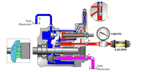
A hydraulic pump operates on positive displacement, where a confined fluid is subjected to pressure using a reciprocating or rotary action. The pump"s driving force is supplied by a prime mover, such as an electric motor, internal combustion engine, human labor (Figure 1), or compressed air (Figure 2), which drives the impeller, gear (Figure 3), or vane to create a flow of fluid within the pump"s housing.
A hydraulic pump’s mechanical action creates a vacuum at the pump’s inlet, which allows atmospheric pressure to force fluid into the pump. The drawn in fluid creates a vacuum at the inlet chamber, which allows the fluid to then be forced towards the outlet at a high pressure.
Vane pump:Vanes are pushed outwards by centrifugal force and pushed back into the rotor as they move past the pump inlet and outlet, generating fluid flow and pressure.
Piston pump:A piston is moved back and forth within a cylinder, creating chambers of varying size that draw in and compress fluid, generating fluid flow and pressure.
A hydraulic pump"s performance is determined by the size and shape of the pump"s internal chambers, the speed at which the pump operates, and the power supplied to the pump. Hydraulic pumps use an incompressible fluid, usually petroleum oil or a food-safe alternative, as the working fluid. The fluid must have lubrication properties and be able to operate at high temperatures. The type of fluid used may depend on safety requirements, such as fire resistance or food preparation.
Air hydraulic pump:These pumps have a compact design and do not require an external power source. However, a reliable source of compressed air is necessary and is limited by the supply pressure of compressed air.
Electric hydraulic pump:They have a reliable and efficient power source and can be easily integrated into existing systems. However, these pumps require a constant power source, may be affected by power outages, and require additional electrical safety measures. Also, they have a higher upfront cost than other pump types.
Gas-powered hydraulic pump:Gas-powered pumps are portable hydraulic pumps which are easy to use in outdoor and remote environments. However, they are limited by fuel supply, have higher emissions compared to other hydraulic pumps, and the fuel systems require regular maintenance.
Manual hydraulic pump:They are easy to transport and do not require a power source. However, they are limited by the operator’s physical ability, have a lower flow rate than other hydraulic pump types, and may require extra time to complete tasks.
Hydraulic hand pump:Hydraulic hand pumps are suitable for small-scale, and low-pressure applications and typically cost less than hydraulic foot pumps.
Hydraulic foot pump:Hydraulic foot pumps are suitable for heavy-duty and high-pressure applications and require less effort than hydraulic hand pumps.
Hydraulic pumps can be single-acting or double-acting. Single-acting pumps have a single port that hydraulic fluid enters to extend the pump’s cylinder. Double-acting pumps have two ports, one for extending the cylinder and one for retracting the cylinder.
Single-acting:With single-acting hydraulic pumps, the cylinder extends when hydraulic fluid enters it. The cylinder will retract with a spring, with gravity, or from the load.
Double-acting:With double-acting hydraulic pumps, the cylinder retracts when hydraulic fluid enters the top port. The cylinder goes back to its starting position.
Single-acting:Single-acting hydraulic pumps are suitable for simple applications that only need linear movement in one direction. For example, such as lifting an object or pressing a load.
Double-acting:Double-acting hydraulic pumps are for applications that need precise linear movement in two directions, such as elevators and forklifts.
Pressure:Hydraulic gear pumps and hydraulic vane pumps are suitable for low-pressure applications, and hydraulic piston pumps are suitable for high-pressure applications.
Cost:Gear pumps are the least expensive to purchase and maintain, whereas piston pumps are the most expensive. Vane pumps land somewhere between the other two in cost.
Efficiency:Gear pumps are the least efficient. They typically have 80% efficiency, meaning 10 mechanical horsepower turns into 8 hydraulic horsepower. Vane pumps are more efficient than gear pumps, and piston pumps are the most efficient with up to 95% efficiency.
Automotive industry:In the automotive industry, hydraulic pumps are combined with jacks and engine hoists for lifting vehicles, platforms, heavy loads, and pulling engines.
Process and manufacturing:Heavy-duty hydraulic pumps are used for driving and tapping applications, turning heavy valves, tightening, and expanding applications.
Despite the different pump mechanism types in hydraulic pumps, they are categorized based on size (pressure output) and driving force (manual, air, electric, and fuel-powered). There are several parameters to consider while selecting the right hydraulic pump for an application. The most important parameters are described below:
Source of driving force: Is it to be manually operated (by hand or foot), air from a compressor, electrical power, or a fuel engine as a prime mover? Other factors that may affect the driving force type are whether it will be remotely operated or not, speed of operation, and load requirement.
Speed of operation: If it is a manual hydraulic pump, should it be a single-speed or double-speed? How much volume of fluid per handle stroke? When using a powered hydraulic pump, how much volume per minute? Air, gas, and electric-powered hydraulic pumps are useful for high-volume flows.
Portability: Manual hand hydraulic pumps are usually portable but with lower output, while fuel power has high-output pressure but stationary for remote operations in places without electricity. Electric hydraulic pumps can be both mobile and stationary, as well as air hydraulic pumps. Air hydraulic pumps require compressed air at the operation site.
Operating temperature: The application operating temperature can affect the size of the oil reservoir needed, the type of fluid, and the materials used for the pump components. The oil is the operating fluid but also serves as a cooling liquid in heavy-duty hydraulic pumps.
Operating noise: Consider if the environment has a noise requirement. A hydraulic pump with a fuel engine will generate a higher noise than an electric hydraulic pump of the same size.
Spark-free: Should the hydraulic pump be spark-free due to a possible explosive environment? Remember, most operating fluids are derivatives of petroleum oil, but there are spark-free options.
A hydraulic pump transforms mechanical energy into fluid energy. A relatively low amount of input power can turn into a large amount of output power for lifting heavy loads.
A hydraulic pump works by using mechanical energy to pressurize fluid in a closed system. This pressurized fluid is then used to drive machinery such as excavators, presses, and lifts.
A hydraulic ram pump leverages the energy of falling water to move water to a higher height without the usage of external power. It is made up of a valve, a pressure chamber, and inlet and exit pipes.
A water pump moves water from one area to another, whereas a hydraulic pump"s purpose is to overcome a pressure that is dependent on a load, like a heavy car.
This website is using a security service to protect itself from online attacks. The action you just performed triggered the security solution. There are several actions that could trigger this block including submitting a certain word or phrase, a SQL command or malformed data.

Every OEM says it wants quality, but the reality is that machine builders can choose from countless hydraulic components that vary widely in performance and price—from cheap, “throw-away” parts to high-quality and, more-expensive, products that are built to last.
How does an engineer sort out the various offerings? Here’s a look at one fluid-power manufacturer’s unique philosophy on making a well-crafted pump, thanks to a keen understanding of how poorly built pumps fail.
Most pump designers begin with theoretical concepts of fluid power and mechanical engineering to create a product that should suit the customer’s needs. Hydraulics manufacturer Permco Inc., based in Streetsboro, Ohio, has taken a different tack on the route to building high-quality parts.
Permco’s roots began in the early 20th century as a small shop servicing Appalachian mining equipment. “Unlike most traditional manufacturers, we got our start in this industry on the repair side. We had the chance to start at the opposite end of the learning curve—with failures—and looked at all the things that could possibly go wrong,” said Robby Shell, the company’s chief operating officer.
It’s hard to imagine worse operating conditions for hydraulics than in underground coal mines, he explained. Mechanics routinely dealt with units with internal parts burned due to overheating, seized from lack of lubrication, fouled with contaminants or damaged due to overpressure conditions. They also learned firsthand a sense of urgency to make a repair right the first time and get machines up and running quickly, as the cost of unexpected breakdowns can run into the tens of thousands of dollars an hour.
“So from that rebuild failure analysis experience, we got to see what impact engineering design, manufacturing processes and quality control, as well as operating conditions and servicing, played on the overall performance and life of components,” Shell continued.
“By virtue of our background, we got to see what worked and didn’t work, and what failed under normal circumstances. Therefore, when we started to manufacture these parts, we had the benefit of touching thousands of failed units before we ever made our first new one,” said Shell.
“Take our gear pumps. We looked at many designs and the best gear design, based on our experience in differentials and transmissions for these applications, has a gear tooth that is shaped vertically, and then shaved after the shaping process,” he said.
Why? Well, cutting a gear tooth vertically produces little tiny cut marks, he indicated. Left as is, those imperfections would grind against each other, generate noise and wear debris, and hurt efficiency. A post-machining shaving process, however, removes the marks and smooths the face for quiet operations, and it also ensures parallel contact between the housing and gear profile.
In contrast, virtually every other competitor cuts their gears on horizontal hobbing machines, said Shell. “Just by the nature of a hobbing tool, those gears will have a crowned profile from end to end. When new, the difference isn’t noticeable.” But over time, as the gears rotate against each other and the housing, a crowned gear creates leak paths. Pumps with vertically cut gears, in contrast, have a straighter tooth profile and wear more uniformly, and thus maintain efficiencies longer, he said. “We were gear cutters in the old days, and that background taught us to implement design features that enhance the operation of our pumps. The way we shape and shave our gears creates a better tooth profile.”
Some hydraulics manufacturers rely on their own foundries and pour their own housing castings. “Well, in the foundry world, technology is really, really expensive. Upgrades are very costly, so there is a natural reluctance against constantly investing in the newest systems,” noted Shell.
Companies like Permco aren’t boxed in. They have the luxury of choosing foundries that rely on the latest and best technology. Not only are there cosmetic differences between state-of-the-art castings versus older offerings. It also results in higher density and fewer porosity issues, which translate into better mechanical integrity and machinability.
Another differentiator among pump manufacturers, in Shell’s view, is that some make high-quality, well-engineered products, and others either don’t understand the basics or simply don’t care.
“For instance, some years ago Permco developed a game-changing thrust plate called a diverter plate,” he said. When subjected to system pressure, the gears in a pump tend to flex and move toward the low-pressure side. To compensate, company engineers developed thrust plates incorporating precision grooves that create a minute flow path to divert high-pressure fluid to the inlet side. In turn, that helps balance bearing loads.
When the patents expired some competitors copied the plates and, without understanding why the feature is there, went one step further and introduced a bi-rotational version—with flow paths in both directions for running a pump clockwise and counterclockwise. They surmised that if the diverter works in one direction, a design suited for both directions would be even better. In reality, the bi-ro design doesn’t work because it creates too many leak paths and efficiency drops severely. But unsophisticated pump builders don’t know that. “We see a lot of those types of issues. They don’t understand the nuances of what this groove really does. They know it has 14° a chamfer on it. Why 14° not 16°? They can’t tell you those things,” said Shell.
Not only do such differences matter in design and manufacturing, they hold for how pumps are assembled, too. Building a high-quality pump is meticulous work, stressed Shell. “Our people do prep work very similar to what you would see in a good engine rebuild shop.” For instance, they might take a honing stone or emery cloth and kiss a few areas on the gear before installation. That’s because when gears are pulled from a warehouse shelf and moved to the assembly station, it’s not unheard of to accidentally bump and nick a gear. If that gear gets assembled as is, and it subsequently rides on the soft bronze plate, the burr will cut a groove and create a leak path. Left unchecked, that pump will run inefficiently and underperform. Few manufacturers take such a hands-on approach to quality, emphasized Shell.
“But probably the biggest thing that differentiates us is we test every pump that goes out of this building. For peace of mind from the customer’s standpoint, that’s huge,” he stressed. Each pump gets assembled with new parts to create a tight package. Then it’s run up to 2,000 psi pressure, where the components flex and the gears will take a take a slight wipe—removing perhaps 0.0005 to 0.001 in. of material from the housing. That’s acceptable, notes Shell, because filters on the test benches trap the wear particles, instead of remaining behind to contaminate a customer’s hydraulic system.
Tests confirm leak-free and quiet operation and that flow meets design specs. And any problem gets flagged immediately, not at the customer’s site. It’s a significant undertaking. That’s why most other manufacturers only test 1 in 10 or 1 in 50 units, said Shell.
Finally, the approved product is assigned a serial number that includes the initials of the assembler—as a further sign of the workmanship that stands behind a high-quality pump.
“I guarantee you many other manufacturers don’t take the extra care we put into these units,” said Shell, and it shows when they test competing products. “Some of the dump-truck pumps coming in from offshore sources—mainly China—have failure rates upwards of 10 to 15%. Ours is less than one quarter of 1%.”
It’s due to a different mindset behind the way they build pumps, versus Permco’s philosophy, he emphasized. Some manufacturers feel units made to less-stringent standards are acceptable because often, they only see light duty. Take the case of a typical dump truck: the duty cycle for the hydraulics is often quite limited, he noted. Generally, a truck gets loaded, transports material to a site, and only then is the pump switched on—where it operates for perhaps a minute to raise, dump and lower the bed. And the cycle might get repeated perhaps a dozen times per day.
So, in theory, a dump pump designed and built to handle just light, intermittent duty should be more than adequate, he continued. But the world isn’t perfect—many things can and will go wrong, said Shell. For instance, the operator keeps the pump on too long and it overheats; or it runs low on oil; or the truck bed is overloaded, and a pump with no margin of safety is overtaxed and fails.
A well-engineered, high-quality pump can overcome many of these issues; lesser products can’t, he said. “We understand how offshore units are built and we can predict, generally speaking, how they will fail.” Almost all of these areas of weakness get addressed in Permco’s engineering, manufacturing, assembly and testing processes—steps that are missing in pumps coming from offshore sources. But those manufacturers justify an increased failure rate because their pump costs $50 less to make, said Shell.
“We saw the invasion of these offshore dump pumps a few years ago, and we had plenty of opportunity to make this same pump in China. So we had two choices in that market. Either join it, and it’s just a race to the bottom. Or offer something that differentiates us from the rest of the market.” That’s where the American Champ, Permco’s pumps like the Gemini series comes in, he explained.
The pumps are engineered and manufactured based on Permco’s years of experience, and assembled in the U.S. from globally sourced, world-class components. What’s interesting is that many of the pump components are made not only in the company’s Ohio plant, but in Permco’s manufacturing operation in Tianjin, China.
“There’s virtually zero difference between our China and U.S. products, and there’s a reason for that,” explained Shell. Instead of relying on subcontractors or joint ventures, 16 years ago the U.S. plant manager (now with 44 years of experience) moved to China to set up a gear manufacturing plant, with processes identical to those in the domestic plant. By installing the same types of machine tools, instituting the same procedures, and with in-depth training and constant supervision, the Chinese workers have come to understand how important quality really is.
“It’s all about a different way of thinking. Again, we came out of the mining component repair world. When a Joy mining machine breaks down and sits idle for 16 hours, and a rebuilt transmission gets carted six miles underground to make the repair, it is imperative that when power is switched on, the work was done right.” The focus is on getting the equipment up and running again, not on saving a few dollars on a pump that might fail in short order, or may not work at all.
Dump pumps, as the name indicates, are routinely used in hydraulic circuits for lifting and lowering dump truck and trailer beds. The basic design typically includes a pump section, a directional control valve and a relief valve incorporated into the pump as a complete package, with internal fluid connections to the components. They have been around for more than 50 years and are common throughout the industry.
A notable innovation is now shaking up that market. Permco has developed a unit that sets it apart from conventional dump pumps. The Gemini DG-20/RG-20 is designed for-dual use applications, thanks to a second set of relief valves and selector valves. That lets the Gemini not only control a dump bed, it can also control a walking (live) floor.
Walking floors are used on trailers that do not tip, like a dump trailer. Instead, slats on the movable floor transport and “walk” the load off the end. They’re frequently used in the refuse industry, in landscaping to handle mulch and wood chips, and in other areas where height restrictions would severely limit the capability to raise a dump bed.
Walking-floor trailers tend to operate at higher pressures than hydraulics in dump applications. Traditionally, that has meant a fleet operator with dump trucks requires separate tractors for walking floors. Now, thanks to the Gemini pump, an operator can run a dump truck, and then switch the same tractor to a trailer with a walking floor. Equipping the vehicle with a Gemini pump system lets the operator easily change pressure settings on demand, and eliminates the need for a dedicated rig that can easily cost $150,000.
Another notable engineering feature is that the Gemini also incorporates a load check feature into the valve design, letting the operator raise the bed and then hold the load in place—say when spreading asphalt. To enhance reliability, the design differs from conventional units in that it’s direct-acting.
Typical designs incorporate a load check into a pilot-operated relief valve. As a result, the tiny orifice pilot senses operating pressure before it activates, but the orifice can easily get plugged by contaminants and the valve fails. The Permco direct-acting relief valve eliminates orifice plugging issues.
The load check and relief are also self-cleaning. Because it mounts in the flow stream, and clearances are sufficiently large, contaminants are flushed away—so there are few occurrences where the relief valve can’t open or close and a bed drifts or hangs up. That, according to Permco officials, offers a distinct advantage over competing designs.
The Gemini is rated for 37 gpm at 1,800 gpm and runs at two pressures, low (2,000 psi) for dump bodies and high (typically 3,200 psi) for live floors. Operators can easily switch from low to high pressure using cab-mounted controls. The pump includes dowelled construction and is assembled in the U.S. and 100% factory tested. In addition to use on dump trailers and walking floors, the Gemini is also suitable for gooseneck transporters, dump trucks, crane-equipment vehicles, roll-off trucks and refuse collection

The items Caterpillar finds suitable for remanufacturing include engines, fuel pumps, injectors, oil coolers, cylinder packs and hydraulic assemblies – each of which must be exhaustively taken apart by hand.
He invented a hydraulic-powered, mechanical puppet theater designed for Emperor Ming of Wei; square-pallet chain pumps for irrigation of gardens in Luoyang; and the ingenious design of the South Pointing Chariot, a non-magnetic directional compass operated by differential gears.
In some cases, treatment can involve prostaglandin tablets in the urethra, injections into the penis, a penile prosthesis, a penis pump, or vascular reconstructive surgery.
Additional treatments for ED are varied and include a purpose-designed external vacuum pump used to attain erection, with a separate compression ring fitted to the penis to maintain it.
These pumps should be distinguished from other penis pumps (supplied without compression rings) which, rather than being used for temporary treatment of impotence, are claimed to increase penis length if used frequently, or vibrate as an aid to masturbation.
Just as with motors, most pumps are bigger and more powerful than they need to be because in many cases production designers did not know what the exact pumping requirements were when the pumping system was being planned.
Obviously, this is not an efficient practice – pa


 8613371530291