
wheel horse hydraulic pump free sample
EQ Systems offers hydraulic lifting & leveling systems for the RV, horse trailer, motorsports, & commercial industries including options for hydraulic landing gear. With EQ Harness we also offer custom wire harnesses.
- One potential diagnostic: If the system is back together enough, fill the 700 via the reservoir up to having the oil just come into the bottom of the reservoir (you may have to do this a second time after running the pump/motor briefly to be sure any trapped air in there has a chance to come out). Run the tractor enough to get the pump/motor really warm (idling will not do it, it has to have a load). The oil should rise in the reservoir due to expansion up to maybe ½ or ⅔ of the tank. First, observe its performance. Second, immediately swab out a sample of the oil from the reservoir and spread it on a clean piece of white paper. You are looking for metal particles or other debris which indicates excess internal wear. If performance is now OK and no particles or debris in the oil, no need to go further, keep the 700.
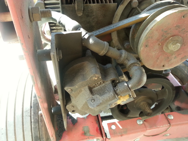
- Yes, that is an 1100. It is black because it was in a Wheel Horse "economy line" Work Horse (I"m not at all familiar with those tractors, but other members are). From what I recall, the transaxles and pump/motor were the same across both lines--I don"t know if Work Horses used hydraulic lifts but I would assume yes given that they had the 1100.
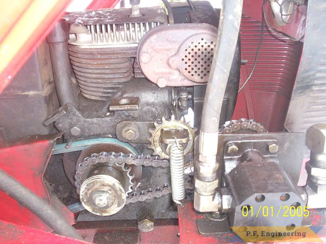
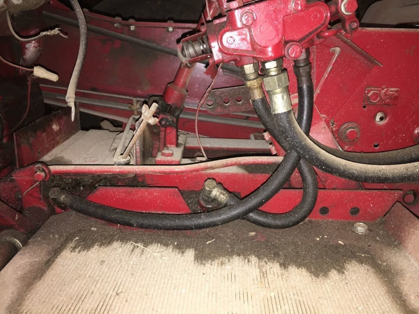
- I"d want the info on the pump"s ID plate (1100"s had a number of models over the years with some nice improvements). The oil filter and mount are there as is at least some of the critical plumbing (not sure about that piece of fuel line next to the bottom of the dipstick tube
- What you cannot see, and is to me important, is the condition of the oil. In an 1100, the oil does three things: it bathes the transaxle gears and differential, it flows through the motion pump/motor, and it circulates out to the hydraulic lift cylinder. The transaxle can stand some abuse, but the hydro pump/motor is sensitive to rust or other contamination. It becomes a question of provenance of the unit and trust in the seller--especially if you cannot examine it first hand. Some questions I"d ask:
How long has this unit had its filter input line disconnected? When the charge pump output plugged? How was it stored since being removed (has moisture had a chance to enter?
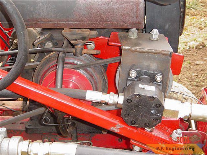
- Yes, the section just inside the drive pulley is the charge pump (up to 700psi at 1.3 gpm, requires external pressure relief--WH control valves used with this pump had built in pressure relief).
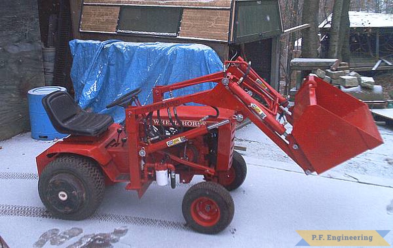
- Yes, you could retrofit your tractor with a hydraulic lift, but it is not a trivial exercise--it goes to the very center of a 300-series tractor"s assembly (I posted some of the issues in a different context in this thread).

I"ve been working to get everything into working order. I have been disassembling and cleaning, looking to see what needs repair/replacement along the way. I had to cut out the pivot pin for the hydraulic cylinder, along with the pivot pin through the slot hitch. On the clevis hitch the PO had a custom fabricated towing plate with a pin that pinned the plate through the clevis hitch pivot. I was able to get the slot hitch to rotate with respect to the transmission case, but the ends of the pin weren"t moving. I ended up sawzalling it out. I"ll need to remove the remnants of the pin from the slot hitch with the press or mill. Here"s some pics-
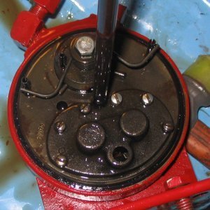
Everything is in solid condition, but is dirty and seems to not have been touched in many years. When I took out the hydraulic cylinder and pump, the old fabric lines tore in half and spit what fluid was left in the reserviour onto my floor. I need to replace the seals in my pump and it looks like the needle bearing is missing one of the needles. It feels a little rough when I rotate the input shaft, but not terrible. It seems like there shouldn"t be as much gap as there is, but I"d be suprised if this thing has been popped open before to allow a needle to fall out.
I know a lot of you guys have re-built these pumps. Have you seen anything similar, with the gap in the needle bearing? Is it definitely in need of replacement?
����One classy looking tractor led to another. Over the past 12 years Rock has produced 12 custom-built rigs. All of the 4-wheel drive articulated beauties look like they just came off an assembly line.
����After building 2 Wheel Horse models, Rock converted a Cub Cadet model 582. That fully articulated model attracted a lot of attention at local shows. Next he converted a Deere 318 into a 4-WD. After that he did more Deere, WheelHorse, and even Case conversions.
�����I start with the garden tractor chassis and go from there,� says Rock. �The original is dismantled, then I create a chassis that articulates horizontally and vertically and rides on 12 or 16-in. wheels.� He builds his tractors with new hydraulic pumps, fittings and hoses. All of them have hydrostatic power, hydraulic steering and in most cases air cooled engines, except for occasional diesels.
����Rock�s son Robert has become an able assistant the last few years. At age 13, with a mild form of autism, but a strong mechanical aptitude, Robert can completely dismantle an old tractor, take transaxles apart, flush hydraulic systems, put in new gaskets and re-assemble axles. He�s gradually learning welding and takes all the new tractors on their initial test drives.
����He and Robert�s most recent creation is a made-from-scratch replica of a 4-wheel drive Minneapolis Moline. Rock calls that one an A4T-1400 and says it�s the toughest project he�s worked on. �I wanted everything done to scale, so I spent a lot of time measuring, designing and sizing before we ever worked on any metal,� Rock says. He adds that replica tractors he builds in the future will probably cost $10,000 to $12,000 depending on options that an owner wants. Some people have requested a high volume hydraulic system, dual wheels and a 3-pt. hitch.
Custom-Built Articulated Tractors Are A Big Hit TRACTORS Conversions Bob Rock has had a love affair with Wheel Horse garden tractors since he received one as a gift from his uncle nearly 40 years ago In 2001 that love affair took an unusual twist as Rock turned his first Wheel Horse into an articulated garden tractor He says people who saw it thought it was factory-built �����I�ve been a machinist all my life so I wanted it to look as professional as possible � says Rock �Eventually I sold it and figured I might as well build another one � ����One classy looking tractor led to another Over the past 12 years Rock has produced 12 custom-built rigs All of the 4-wheel drive articulated beauties look like they just came off an assembly line ����After building 2 Wheel Horse models Rock converted a Cub Cadet model 582 That fully articulated model attracted a lot of attention at local shows Next he converted a Deere 318 into a 4-WD After that he did more Deere WheelHorse and even Case conversions �����I start with the garden tractor chassis and go from there � says Rock �The original is dismantled then I create a chassis that articulates horizontally and vertically and rides on 12 or 16-in wheels � He builds his tractors with new hydraulic pumps fittings and hoses All of them have hydrostatic power hydraulic steering and in most cases air cooled engines except for occasional diesels ����Rock�s creations all have meticulous metal work because he knows that business well He owns a Hypertherm Powermax 45 cutting system has a brake press and several welders All the work is done on elevated stands and a lift table He bends and shapes sheet metal to produce authentic looking fenders hoods chassis parts and grilles then protects all parts with clear coat paint ����Rock�s son Robert has become an able assistant the last few years At age 13 with a mild form of autism but a strong mechanical aptitude Robert can completely dismantle an old tractor take transaxles apart flush hydraulic systems put in new gaskets and re-assemble axles He�s gradually learning welding and takes all the new tractors on their initial test drives ����Rock and his son enjoy taking the tractors to shows and fairs because people are really intrigued by how they�re made and how they run He�s sold most of the tractors he�s built for $7 000 to $10 000 Some of them he built in a couple hundred hours and others took longer ����He and Robert�s most recent creation is a made-from-scratch replica of a 4-wheel drive Minneapolis Moline Rock calls that one an A4T-1400 and says it�s the toughest project he�s worked on �I wanted everything done to scale so I spent a lot of time measuring designing and sizing before we ever worked on any metal � Rock says He adds that replica tractors he builds in the future will probably cost $10 000 to $12 000 depending on options that an owner wants Some people have requested a high volume hydraulic system dual wheels and a 3-pt hitch �����We�re about a year out for anyone who wants something special made � says Rock �but that�s okay My son and I enjoy working on these and we�re able to make some money at the same time � ���� Contact: FARM SHOW Followup Robert Rock Rock & Son Fabrication Pewamo Mich 48873 ph 989 289-7858; http://articulatedgardentractors weebly com
How much do you hate getting out in the rain heat or cold and cranking the manual jacks on that loaded horse, livestock, gooseneck flatbed, dump, cargo, or car trailer?
As outboard motors or engines are not provided with a power take-off, boats equipped with such motors are at a disadvantage when compared with boats that have inboard engines since the latter commonly have power take-offs. As a consequence, boats powered by outboard motors cannot use hydraulically operated devices such, for example, as trap and seine haulers since such motors have no means to operate a hydraulic pump.
This disadvantage has been recognized and proposals have been made to attach the drive shaft of a hydraulic pump to the fly wheel end of the drive shaft of the outboard by means of a flexible coupling with the pump housing suitably anchored. As far as we are aware, however, such proposals have not been well received because of difficulty in effecting a satisfactory connection between the shafts.
The general objectives of the present invention are to provide outboard motors with hydraulic pumps and to provide means enabling such pumps to be attached to the engines thereof with maximum ease and convenience and ensure efficient pump operation with accommodation of misalignment forces.
In accordance with the invention, these objectives are attained with the fly wheel, or the flywheel and the crankshaft of an outboard motor constituting a support by which a hydraulic pump can be driven. Each pump attachment includes a coupling by which the pump shaft is or may be connected to the support and driven thereby with the weight of the attached pump transmitted to the support. Each attachment also includes resiliently yieldable torque opposing and pump stabilizing means by which a coupled pump may be attached to the motor laterally of its fly wheel.
Another objective of the invention is to provide a coupling in which the torque opposing means accommodate the misalignment forces, an objective attained with the coupling a hub secured to the fly wheel in which the end of the pump shaft is splined and locked thereto and with at least one torque opposing arm secured to the pump and the engine with the connection including a resilient mount.
Another objective of the invention is to provide a coupling that is flexible and capable of accommodating the misalignment forces, an objective attained with the coupling having a drive member fixed on the fly wheel, a driven member locked to the pump shaft and extending through the drive member, a supporting ball joint between the driven member and the upper end of the crankshaft, and a driving connection between the members capable of accommodating misalignment forces.
A further objective of the invention is to ensure pump stability where a flexible coupling is used, an objective attained with the torque opposing means a series of at least three arms connected to or connectable to the motor at three appropriately spaced points, the arms preferably of the type having, at least one end provided with a bolt receiving eye having an elastomerid lining.
FIG. 1 is a perspective view of an outboard engine or motor with a hydraulic device operating system, the pump of which is driven by the outboard engine;
A typical outboard engine or motor having a horse power rating adequate for use by commercial fishermen is generally indicated at 10 in FIG. 1. The casing of such a motor includes an upper portion 11 which, when removed exposes the engine 12, and its fly wheel 13. The nut 14 by which the fly wheel 13 is secured to the upper end of the engine crankshaft is partly within a coaxial cylindrical recess or seat 14 within which are screw holes 16 by which a fly wheel attachment or pulley may be secured.
Hydraulic systems suitable for installation on small boats are, of course, well known. Such systems include a hydraulic pump 17, an oil chamber 18 having a hose 19 placing it in communication with the intake side of the pump 17. A hose 20 connects the discharge of its pump 17 to the four-way valve 21 having an actuator 22 by which the direction of flow through the hose lines 23 and 24 to and from the device controlling its operation in the desired manner. Such a device is indicated schematically at 25 and it may, for examples, be a pot or seine hauler, a gil net reel, a deck winch, or a power boom. The valve is also provided with a return hose 26 connected to the chamber 18 through an oil filter 27. Thus, with the pump 17 in use, oil circulates through the valve 21 or if the valve is set to operate the device 25 in one direction or the other, the circulation is through the hose lines 23 and 24 in the appropriate direction and through the return line 26.
In order to utilize the engine 12 to drive the pump 17, the pump 17 must be mounted with its drive shaft 28 connected to the fly wheel and its casing 29 secured and in accordance with the invention, attachments are provided to enable such an installation to be effected.
The attachment illustrated by FIGS. 1-3 includes a coupling in the form of a hub member 30 having a cylindrical boss 31 concentric with an axial bore 32 extending downwardly therethrough with its lower end counterbored as at 33 to fit over the nut 14. The boss 31 is dimensioned to be a precision fit in the recess 15 and the hub 30 has bores 34 receiving screws 35 which, when threaded into the screw holes 16, enable the hub 30 to be clamped to the fly wheel 13. It will be noted that the bores 34 are oversized so that the screws 35, while a loose fit therein, serve to clamp the hub 30 in place and permit the accurate centering of the hub to ensure that the axis of its bore 32 is in vertical alignment with the axis of the crankshaft without requiring that the screw holes be precisely located but rather depending on the fit of the boss 31 in the cylindrical recess 15 which serves as a positive centering seat therefor. Thus, if the fly wheel is not made with such a seat, it has such a cylindrical seat machined therein.
The pump casing 29 is detachably secured to a torque arm 36 having a port 37 through which the pump shaft 28 freely extends downwardly into the hub bore 32 which is dimensioned to receive it with a slidable connection between them, either a splined or key and keyway connection, a splined connection being shown in FIG. 3. The pump shaft 28 is locked to the hub 30 by a set screw 38 so that the fly wheel 13 is the support to which the weight of the pump 17 is transmitted with the function of the torque arm 36 that of pump stabilizing and opposing torque. To that end, the arm 36 is of sufficient length to extend beyond the periphery of the fly wheel 13 and over some part of the engine that serves as or can be easily converted into a seat 39 and provided with threaded bores 40 to enable the base of a resilient mount 41, shown as of an elastomeric type, to be secured thereto by screws 42. The mount 41 has threaded sockets 43 to enable the arm 36 to be secured thereto by screws 44 with the arm 36 held above the hub 30, in the described embodiment, the spacing effected by the height of the mount 41. With the pump 17 thus mounted, the casing 11 may be cut to accommodate it and a cap 45 that is provided fits over the pump 17 and is sealed to the casing 11.
In the embodiment of the invention illustrated by FIGS. 4-6, the fly wheel 46 and the upper end of the crankshaft 47 of the engine 48 are both used as the support for the pump 49.
The coupling of the attachment includes a flanged driving member 50 having a bore or chamber 51 extending vertically therethrough. The drive member 50 is clamped to the fly wheel 46 by screws 51. A driven member 52 is keyed to the end of the shaft 53 of the pump 49 and is also locked thereto by a set screw 54 accessible through a port 55 in the driving member 50.
The upper end of the crankshaft 47 has an axial seat 61 for a ball 62 and the lower end of the driven member 52 has a recess 63 for a seat 64 fitting the upper portion of the ball 62 so that the weight of the pump 49 is supported directly by the crankshaft 47.
The pump 49 is bolted to a holder 65 having oppositely disposed, depending flanges 66. Three torque opposing stabilizing arms 67 are provided and each has a bolt-receiving eye 68 threaded on each end. Two of the arms 67 are bolted at one end to one flange 66 adjacent the ends thereof and have their other ends bolted to a bracket 69 fixed on the engine 48 at one side of the fly wheel 46, the eyes 68 at the last named arm ends provided with elastomeric linings 70. The other arm 67 has one end bolted to the other flange 66 and its other end similarly attached to a bracket 71 fixed on the engine 48 on the opposite side of the fly wheel 46 with the eye 68 at the last named arm end also having an elastomeric lining 70.
The casing of the outboard motor of FIG. 1 has its upper portion 72 cut away and provided with a cap 73 dimensioned to accommodate the attached pump 49.
Combustion engines, like those found in most cars, transfer power to the vehicle’s axle, which turns the wheels. Hydrostatic transmissions found in most modern tractors and zero-turn mowers, work by transferring power from the engine to hydraulic pumps which use liquid pressure to move the wheels. There’s no need for gears, and changing speed is smooth and efficient.
Zero turn hydrostatic transmission problems can start with air in the system, a condition known as cavitation. When the pump is full of air instead of oil, it can’t generate the pressure needed to provide power. This is pretty common in zero-turn mower transmissions. After your mower has been stored for the winter, it’s a good idea to purge the transmission before use. It’s also a good first step if your motor is sluggish or slow.
If your system is purged and you still have a problem, it’s time to do a little basic troubleshooting. Start with a complete visual check of the hydraulic system.
Sluggish operation is often due to old or overused fluids. If there are no signs of fluid leaks or damage, it may be time to change your hydraulic and steering fluids.
If you need help troubleshooting your tractor’s hydraulic system, call your dealer. Their service department should be able to ask the right questions, give suggestions, and you can make an appointment for service if necessary.
I picked up two Wheel Horse 953s a few months ago. They were built one year only in 1963, though in 1964 Wheel Horse built a 1054 which was basically an upgraded 953. The 953 has a 9.6 single cylinder Kohler K-series engine, 3 speed gear drive transmission and hydraulic lift. It has 16 inch front tires on 8 inch rims and 27 inch rear tires on 15 inch rims. They are heavy built garden tractors.
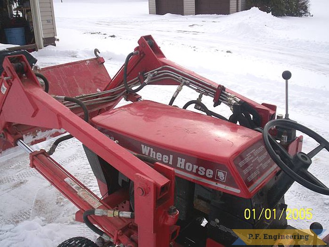
As you can see, I moved the boat seat to the running tractor. It would be great if I can get both of them going and plowing like the 953 shown in these youtube videos. These videos was posted on Red Square Wheel Horse forum.
The running 953 also has an issue with the hydraulic lift. Moving the handle doesn"t affect the pump, so that will have to be address. Here is a video of it running and one showing the non-operation of the hydraulic lift handle.
Horsepower (hp) is a unit of measurement of power, or the rate at which work is done, usually in reference to the output of engines or motors. There are many different standards and types of horsepower. Two common definitions used today are the mechanical horsepower (or imperial horsepower), which is about 745.7 watts, and the metric horsepower, which is approximately 735.5 watts.
The term was adopted in the late 18th century by Scottish engineer James Watt to compare the output of steam engines with the power of draft horses. It was later expanded to include the output power of other types of piston engines, as well as turbines, electric motors and other machinery.SI unit watt for measurement of power. With the implementation of the EU Directive 80/181/EEC on 1 January 2010, the use of horsepower in the EU is permitted only as a supplementary unit.
The development of the steam engine provided a reason to compare the output of horses with that of the engines that could replace them. In 1702, Thomas Savery wrote in The Miner"s Friend:
So that an engine which will raise as much water as two horses, working together at one time in such a work, can do, and for which there must be constantly kept ten or twelve horses for doing the same. Then I say, such an engine may be made large enough to do the work required in employing eight, ten, fifteen, or twenty horses to be constantly maintained and kept for doing such a work...
Watt determined that a horse could turn a mill wheel 144 times in an hour (or 2.4 times a minute).2.4 × 2π × 12 feet in one minute. Watt judged that the horse could pull with a force of 180 pounds-force (800 N). So:
Engineering in History recounts that John Smeaton initially estimated that a horse could produce 22,916 foot-pounds (31,070 J) per minute.John Desaguliers had previously suggested 44,000 foot-pounds (59,656 J) per minute, and Tredgold suggested 27,500 foot-pounds (37,285 J) per minute. "Watt found by experiment in 1782 that a "brewery horse" could produce 32,400 foot-pounds [43,929 J] per minute."
A common legend states that the unit was created when one of Watt"s first customers, a brewer, specifically demanded an engine that would match a horse, and chose the strongest horse he had and driving it to the limit. Watt accepted the challenge and built a machine that was actually even stronger than the figure achieved by the brewer, and the output of that machine became the horsepower.
In certain situations it is necessary to distinguish between the various definitions of horsepower and thus a suffix is added: hp(I) for mechanical (or imperial) horsepower, hp(M) for metric horsepower, hp(S) for boiler (or steam) horsepower and hp(E) for electrical horsepower.
Assuming the third CGPM (1901, CR 70) definition of standard gravity, gn = 9.80665 m/s2, is used to define the pound-force as well as the kilogram force, and the international avoirdupois pound (1959), one mechanical horsepower is:
The various units used to indicate this definition (PS, KM, cv, hk, pk, ks and ch) all translate to horse power in English. British manufacturers often intermix metric horsepower and mechanical horsepower depending on the origin of the engine in question.
DIN 66036 defines one metric horsepower as the power to raise a mass of 75 kilograms against the Earth"s gravitational force over a distance of one metre in one second:75 kg × 9.80665 m/s2 × 1 m / 1 s = 75 kgf⋅m/s = 1 PS. This is equivalent to 735.49875 W, or 98.6% of an imperial mechanical horsepower. In 1972, the PS was replaced by the kilowatt as the official power-measuring unit in EEC directives.
Other names for the metric horsepower are the Italian cavallo vapore (cv), Dutch paardenkracht (pk), the French cheval-vapeur (ch), the Spanish caballo de vapor and Portuguese cavalo-vapor (cv), the Russian лошадиная сила (л. с.), the Swedish hästkraft (hk), the Finnish hevosvoima (hv), the Estonian hobujõud (hj), the Norwegian and Danish hestekraft (hk), the Hungarian lóerő (LE), the Czech koňská síla and Slovak konská sila (k or ks), the Bosnian/Croatian/Serbian konjska snaga (KS), the Bulgarian конска сила, the Macedonian коњска сила (KC), the Polish koń mechaniczny (KM), Slovenian konjska moč (KM), the Ukrainian кінська сила (к. с.), the Romanian cal-putere (CP), and the German Pferdestärke (PS).
In the 19th century, the French had their own unit, which they used instead of the CV or horsepower. Based on a 100 kgf⋅m/s standard, it was called the poncelet and was abbreviated p.
Tax or fiscal horsepower is a non-linear rating of a motor vehicle for tax purposes.2 emissions, so are not directly comparable to older ratings. The Citroën 2CV is named for its French fiscal horsepower rating, "deux chevaux" (2CV).
Nameplates on electrical motors show their power output, not the power input (the power delivered at the shaft, not the power consumed to drive the motor). This power output is ordinarily stated in watts or kilowatts. In the United States, the power output is stated in horsepower, which for this purpose is defined as exactly 746 W.
Drilling rigs are powered mechanically by rotating the drill pipe from above. Hydraulic power is still needed though, as 1 500 to 5 000 W are required to push mud through the drill bit to clear waste rock. Additional hydraulic power may also be used to drive a down-hole mud motor to power directional drilling.
Boiler horsepower is a boiler"s capacity to deliver steam to a steam engine and is not the same unit of power as the 550 ft lb/s definition. One boiler horsepower is equal to the thermal energy rate required to evaporate 34.5 pounds (15.6 kg) of fresh water at 212 °F (100 °C) in one hour. In the early days of steam use, the boiler horsepower was roughly comparable to the horsepower of engines fed by the boiler.
The term "boiler horsepower" was originally developed at the Philadelphia Centennial Exhibition in 1876, where the best steam engines of that period were tested. The average steam consumption of those engines (per output horsepower) was determined to be the evaporation of 30 pounds (14 kg) of water per hour, based on feed water at 100 °F (38 °C), and saturated steam generated at 70 psi (480 kPa). This original definition is equivalent to a boiler heat output of 33,485 Btu/h (9.813 kW). A few years later in 1884, the ASME re-defined the boiler horsepower as the thermal output equal to the evaporation of 34.5 pounds per hour of water "from and at" 212 °F (100 °C). This considerably simplified boiler testing, and provided more accurate comparisons of the boilers at that time. This revised definition is equivalent to a boiler heat output of 33,469 Btu/h (9.809 kW). Present industrial practice is to define "boiler horsepower" as a boiler thermal output equal to 33,475 Btu/h (9.811 kW), which is very close to the original and revised definitions.
Boiler horsepower is still used to measure boiler output in industrial boiler engineering in the US. Boiler horsepower is abbreviated BHP, not to be confused with brake horsepower, below, which is also abbreviated BHP.
If the drawbar force (F) is measured in pounds-force (lbf) and speed (v) is measured in miles per hour (mph), then the drawbar power (P) in horsepower (hp) is
Taxable horsepower does not reflect developed horsepower; rather, it is a calculated figure based on the engine"s bore size, number of cylinders, and a (now archaic) presumption of engine efficiency. As new engines were designed with ever-increasing efficiency, it was no longer a useful measure, but was kept in use by UK regulations, which used the rating for tax purposes. The United Kingdom was not the only country that used the RAC rating; many states in Australia used RAC hp to determine taxation.Kenya (British East Africa).
Since taxable horsepower was computed based on bore and number of cylinders, not based on actual displacement, it gave rise to engines with "undersquare" dimensions (bore smaller than stroke), which tended to impose an artificially low limit on rotational speed, hampering the potential power output and efficiency of the engine.
Engine designers use expressions other than horsepower to denote objective targets or performance, such as brake mean effective pressure (BMEP). This is a coefficient of theoretical brake horsepower and cylinder pressures during combustion.
For the nominal horsepower to equal the actual power it would be necessary for the mean steam pressure in the cylinder during the stroke to be 7 psi (48 kPa) and for the piston speed to be that generated by the assumed relationship for paddle ships.
Indicated horsepower (ihp) is the theoretical power of a reciprocating engine if it is completely frictionless in converting the expanding gas energy (piston pressure × displacement) in the cylinders. It is calculated from the pressures developed in the cylinders, measured by a device called an
Indicated horsepower was a better measure of engine power than nominal horsepower (nhp) because it took account of steam pressure. But unlike later measures such as shaft horsepower (shp) and brake horsepower (bhp), it did not take into account power losses due to the machinery internal frictional losses, such as a piston sliding within the cylinder, plus bearing friction, transmission and gear box friction, etc.
Brake horsepower (bhp) is the power measured using a brake type (load) dynamometer at a specified location, such as the crankshaft, output shaft of the transmission, rear axle or rear wheels.
In Europe, the DIN 70020 standard tests the engine fitted with all ancillaries and the exhaust system as used in the car. The older American standard (SAE gross horsepower, referred to as bhp) used an engine without alternator, water pump, and other auxiliary components such as power steering pump, muffled exhaust system, etc., so the figures were higher than the European figures for the same engine. The newer American standard (referred to as SAE net horsepower) tests an engine with all the auxiliary components (see "Engine power test standards" below).
Brake refers to the device which is used to provide an equal braking force / load to balance / equal an engine"s output force and hold it at a desired rotational speed. During testing, the output torque and rotational speed are measured to determine the brake horsepower. Horsepower was originally measured and calculated by use of the "indicator diagram" (a James Watt invention of the late 18th century), and later by means of a Prony brake connected to the engine"s output shaft. Modern dynamometers use any of several braking methods to measure the engine"s brake horsepower, the actual output of the engine itself, before losses to the drivetrain.
Equivalent shaft horsepower (eshp) is sometimes used to rate turboprop engines. It includes the equivalent power derived from residual jet thrust from the turbine exhaust.
In the early twentieth century, a so-called "SAE horsepower" was sometimes quoted for U.S. automobiles. This long predates the Society of Automotive Engineers (SAE) horsepower measurement standards and was another name for the industry standard ALAM or NACC horsepower figure and the same as the British RAC horsepower also used for tax purposes. Alliance for Automotive Innovation is the current successor of ALAM and NACC.
Prior to the 1972 model year, American automakers rated and advertised their engines in brake horsepower, headers in lieu of the OEM exhaust manifolds. This contrasts with both SAE net power and DIN 70020 standards, which account for engine accessories (but not transmission losses). The atmospheric correction standards for barometric pressure, humidity and temperature for SAE gross power testing were relatively idealistic.
SAE tightened its horsepower rules to eliminate the opportunity for engine manufacturers to manipulate factors affecting performance such as how much oil was in the crankcase, engine control system calibration, and whether an engine was tested with high octane fuel. In some cases, such can add up to a change in horsepower ratings.
DIN 70020 is a German DIN standard for measuring road vehicle horsepower. DIN hp is measured at the engine"s output shaft as a form of metric horsepower rather than mechanical horsepower. Similar to SAE net power rating, and unlike SAE gross power, DIN testing measures the engine as installed in the vehicle, with cooling system, charging system and stock exhaust system all connected. DIN hp is often abbreviated as "PS", derived from the German word Pferdestärke (literally, "horsepower").
CUNA prescribed that the engine be tested with all accessories necessary to its running fitted (such as the water pump), while all others – such as alternator/dynamo, radiator fan, and exhaust manifold – could be omitted.
Collins, E. V.; Caine, A. B. (1926). "Testing Draft Horses". Iowa Agricultural Experiment Station Bulletin. 240: 193–223. Archived from the original on 2020-06-07. Retrieved 2021-09-06.


 8613371530291