
where is the hydraulic pump located factory
Founded nearly 25 years ago, Panagon Systems has remained a trusted company producing hydraulic parts on demand for a number of shops, manufacturers and industries. The company, located in Macomb, Michigan, is the largest aftermarket hydraulic piston pump and parts manufacturer in North America, providing a vast variety of current and obsolete components. Panagon has the ability to produce a product from raw materials to a finished pump, assembled, tested, painted and shipped from our facility. Due to the phasing out of old products, customers usually find that the parts they need are no longer available, or that the delivery time is too long or the cost is too high. Panagon Systems attempts to fill the void OEM’s create by manufacturing the phased out, expensive, unavailable pumps, motors and transmissions, from companies like Vickers, Denison and Rexroth.

A global technology leader, the Parker Hydraulic Pump and Power Systems Division brings nearly two centuries of combined experience. Our division is the result of the Parker piston pump business’s acquisition of Denison Hydraulics and merger with the Parker Oildyne Division and the Parker Electromechanical Drives Division’s (EMD) electric motors and gearboxes.
Since before WWII, Denison products have been excelling in military test stand and shipboard hydraulic applications. This acquisition allowed us to enhance and expand the design, manufacturing and application of open- and closed-circuit piston products into new markets. With the addition of Oildyne, we have extended our offering to include the quality compact hydraulic products and systems the division has been pioneering since 1955. Like the miniature piston pumps Oildyne manufactures, it’s been a smart fit.
With the Summer 2021 addition of electric motors and gearboxes from Parker’s EMD, HPS is focused on the future of both electric and hydraulicssolutions. Bycombiningelectricmotors and hydraulic pumps, highly integrated and versatile electro-hydraulicfunctions can be created for a wide variety of applications including trucks, buses, and construction equipment vehicles.
The Hydraulic Pump and Power Systems Division operates four manufacturing locations in the United States. We partner with our overseas manufacturing facilities, Pump & Motor Division Europe, which has four locations across Europe. Together, our teams of application, engineering and manufacturing professionals collaborate on industry leading hydraulic pumps, motors, power units, electro-hydraulic actuators (EHA), and compact systems designs.
The Hydraulic Pump & Power Systems Division is headquartered in Marysville, Ohio, just outside of Columbus. Gold Cup Pumps and Motors, known worldwide for their unparalleled, rugged design are manufactured here. The Marysville facility has been in operation since 1962, originally part of Denison Hydraulics and acquired by Parker in 2004. Safety for our team and visitors is top priority and our record is something we take great pride in. With world class manufacturing and continuous improvement, the Marysville facility is positioned to exceed our customers" expectations as a global supplier. In addition to manufacturing, the Marysville facility houses industry leading closed center pump research, development, and engineering, which is responsible for numerous break throughs and patents. Marysville has one of the largest hydraulic laboratories in North America, including multiple test stands with over 3000 HP of installed power and an extensive Metallurgical lab. We are continuously working to improve our products, to deliver the best quality hydraulic pumps for your applications.
Parker Oildyne, located in New Hope, Minnesota, has been manufacturing top quality compact hydraulic products since 1955. Parker Oildyne merged to become part of Parker’s Hydraulic Pump and Power Systems (HPS) Division in 2015.
Its product line focuses on compact fluid power system solutions requiring flows up to 14.4 liters per minute (3.8 gallons per minute) and pressure to 276 bar (4000 psi), or integrated electro-hydraulic actuators. Parker Oildyne is dedicated to providing solutions for today’s high pressure, space saving, and power-dense hydraulic installations.
For 25 years, our Motor and Gearhead business in New Ulm has delivered high quality products and core expertise to support customer application development. Products from the facility are used in industries, such as aerospace, semiconductor, packaging, robotics, and vehicle electrification. This facility is ISO9001 2015 certified.
Parker’s Hydraulic Pump and Power Systems’ Otsego, Michigan location (a few miles north of Kalamazoo) focuses on the manufacturing of Parker’s superior open circuit variable piston pumps including P1/PD, P2/P3, PAVC, PVP, P1M, and Industrial Power Units.
Safety for our team and visitors is top priority and our record shows this without doubt. With world class manufacturing and continuous improvement, the Otsego facility is positioned well and is constantly improving and out pacing the competition as a global supplier.
In addition to manufacturing, the Otsego facility houses industry leading open center pump research, development, and engineering which is responsible for numerous break throughs and patents. Otsego also has a fully capable pump lab with multiple test stands up to 500 HP.

Every OEM says it wants quality, but the reality is that machine builders can choose from countless hydraulic components that vary widely in performance and price—from cheap, “throw-away” parts to high-quality and, more-expensive, products that are built to last.
How does an engineer sort out the various offerings? Here’s a look at one fluid-power manufacturer’s unique philosophy on making a well-crafted pump, thanks to a keen understanding of how poorly built pumps fail.
Most pump designers begin with theoretical concepts of fluid power and mechanical engineering to create a product that should suit the customer’s needs. Hydraulics manufacturer Permco Inc., based in Streetsboro, Ohio, has taken a different tack on the route to building high-quality parts.
Permco’s roots began in the early 20th century as a small shop servicing Appalachian mining equipment. “Unlike most traditional manufacturers, we got our start in this industry on the repair side. We had the chance to start at the opposite end of the learning curve—with failures—and looked at all the things that could possibly go wrong,” said Robby Shell, the company’s chief operating officer.
It’s hard to imagine worse operating conditions for hydraulics than in underground coal mines, he explained. Mechanics routinely dealt with units with internal parts burned due to overheating, seized from lack of lubrication, fouled with contaminants or damaged due to overpressure conditions. They also learned firsthand a sense of urgency to make a repair right the first time and get machines up and running quickly, as the cost of unexpected breakdowns can run into the tens of thousands of dollars an hour.
“So from that rebuild failure analysis experience, we got to see what impact engineering design, manufacturing processes and quality control, as well as operating conditions and servicing, played on the overall performance and life of components,” Shell continued.
“By virtue of our background, we got to see what worked and didn’t work, and what failed under normal circumstances. Therefore, when we started to manufacture these parts, we had the benefit of touching thousands of failed units before we ever made our first new one,” said Shell.
“Take our gear pumps. We looked at many designs and the best gear design, based on our experience in differentials and transmissions for these applications, has a gear tooth that is shaped vertically, and then shaved after the shaping process,” he said.
Why? Well, cutting a gear tooth vertically produces little tiny cut marks, he indicated. Left as is, those imperfections would grind against each other, generate noise and wear debris, and hurt efficiency. A post-machining shaving process, however, removes the marks and smooths the face for quiet operations, and it also ensures parallel contact between the housing and gear profile.
In contrast, virtually every other competitor cuts their gears on horizontal hobbing machines, said Shell. “Just by the nature of a hobbing tool, those gears will have a crowned profile from end to end. When new, the difference isn’t noticeable.” But over time, as the gears rotate against each other and the housing, a crowned gear creates leak paths. Pumps with vertically cut gears, in contrast, have a straighter tooth profile and wear more uniformly, and thus maintain efficiencies longer, he said. “We were gear cutters in the old days, and that background taught us to implement design features that enhance the operation of our pumps. The way we shape and shave our gears creates a better tooth profile.”
Some hydraulics manufacturers rely on their own foundries and pour their own housing castings. “Well, in the foundry world, technology is really, really expensive. Upgrades are very costly, so there is a natural reluctance against constantly investing in the newest systems,” noted Shell.
Companies like Permco aren’t boxed in. They have the luxury of choosing foundries that rely on the latest and best technology. Not only are there cosmetic differences between state-of-the-art castings versus older offerings. It also results in higher density and fewer porosity issues, which translate into better mechanical integrity and machinability.
Another differentiator among pump manufacturers, in Shell’s view, is that some make high-quality, well-engineered products, and others either don’t understand the basics or simply don’t care.
“For instance, some years ago Permco developed a game-changing thrust plate called a diverter plate,” he said. When subjected to system pressure, the gears in a pump tend to flex and move toward the low-pressure side. To compensate, company engineers developed thrust plates incorporating precision grooves that create a minute flow path to divert high-pressure fluid to the inlet side. In turn, that helps balance bearing loads.
When the patents expired some competitors copied the plates and, without understanding why the feature is there, went one step further and introduced a bi-rotational version—with flow paths in both directions for running a pump clockwise and counterclockwise. They surmised that if the diverter works in one direction, a design suited for both directions would be even better. In reality, the bi-ro design doesn’t work because it creates too many leak paths and efficiency drops severely. But unsophisticated pump builders don’t know that. “We see a lot of those types of issues. They don’t understand the nuances of what this groove really does. They know it has 14° a chamfer on it. Why 14° not 16°? They can’t tell you those things,” said Shell.
Not only do such differences matter in design and manufacturing, they hold for how pumps are assembled, too. Building a high-quality pump is meticulous work, stressed Shell. “Our people do prep work very similar to what you would see in a good engine rebuild shop.” For instance, they might take a honing stone or emery cloth and kiss a few areas on the gear before installation. That’s because when gears are pulled from a warehouse shelf and moved to the assembly station, it’s not unheard of to accidentally bump and nick a gear. If that gear gets assembled as is, and it subsequently rides on the soft bronze plate, the burr will cut a groove and create a leak path. Left unchecked, that pump will run inefficiently and underperform. Few manufacturers take such a hands-on approach to quality, emphasized Shell.
“But probably the biggest thing that differentiates us is we test every pump that goes out of this building. For peace of mind from the customer’s standpoint, that’s huge,” he stressed. Each pump gets assembled with new parts to create a tight package. Then it’s run up to 2,000 psi pressure, where the components flex and the gears will take a take a slight wipe—removing perhaps 0.0005 to 0.001 in. of material from the housing. That’s acceptable, notes Shell, because filters on the test benches trap the wear particles, instead of remaining behind to contaminate a customer’s hydraulic system.
Tests confirm leak-free and quiet operation and that flow meets design specs. And any problem gets flagged immediately, not at the customer’s site. It’s a significant undertaking. That’s why most other manufacturers only test 1 in 10 or 1 in 50 units, said Shell.
Finally, the approved product is assigned a serial number that includes the initials of the assembler—as a further sign of the workmanship that stands behind a high-quality pump.
“I guarantee you many other manufacturers don’t take the extra care we put into these units,” said Shell, and it shows when they test competing products. “Some of the dump-truck pumps coming in from offshore sources—mainly China—have failure rates upwards of 10 to 15%. Ours is less than one quarter of 1%.”
It’s due to a different mindset behind the way they build pumps, versus Permco’s philosophy, he emphasized. Some manufacturers feel units made to less-stringent standards are acceptable because often, they only see light duty. Take the case of a typical dump truck: the duty cycle for the hydraulics is often quite limited, he noted. Generally, a truck gets loaded, transports material to a site, and only then is the pump switched on—where it operates for perhaps a minute to raise, dump and lower the bed. And the cycle might get repeated perhaps a dozen times per day.
So, in theory, a dump pump designed and built to handle just light, intermittent duty should be more than adequate, he continued. But the world isn’t perfect—many things can and will go wrong, said Shell. For instance, the operator keeps the pump on too long and it overheats; or it runs low on oil; or the truck bed is overloaded, and a pump with no margin of safety is overtaxed and fails.
A well-engineered, high-quality pump can overcome many of these issues; lesser products can’t, he said. “We understand how offshore units are built and we can predict, generally speaking, how they will fail.” Almost all of these areas of weakness get addressed in Permco’s engineering, manufacturing, assembly and testing processes—steps that are missing in pumps coming from offshore sources. But those manufacturers justify an increased failure rate because their pump costs $50 less to make, said Shell.
“We saw the invasion of these offshore dump pumps a few years ago, and we had plenty of opportunity to make this same pump in China. So we had two choices in that market. Either join it, and it’s just a race to the bottom. Or offer something that differentiates us from the rest of the market.” That’s where the American Champ, Permco’s pumps like the Gemini series comes in, he explained.
The pumps are engineered and manufactured based on Permco’s years of experience, and assembled in the U.S. from globally sourced, world-class components. What’s interesting is that many of the pump components are made not only in the company’s Ohio plant, but in Permco’s manufacturing operation in Tianjin, China.
“There’s virtually zero difference between our China and U.S. products, and there’s a reason for that,” explained Shell. Instead of relying on subcontractors or joint ventures, 16 years ago the U.S. plant manager (now with 44 years of experience) moved to China to set up a gear manufacturing plant, with processes identical to those in the domestic plant. By installing the same types of machine tools, instituting the same procedures, and with in-depth training and constant supervision, the Chinese workers have come to understand how important quality really is.
“It’s all about a different way of thinking. Again, we came out of the mining component repair world. When a Joy mining machine breaks down and sits idle for 16 hours, and a rebuilt transmission gets carted six miles underground to make the repair, it is imperative that when power is switched on, the work was done right.” The focus is on getting the equipment up and running again, not on saving a few dollars on a pump that might fail in short order, or may not work at all.
Dump pumps, as the name indicates, are routinely used in hydraulic circuits for lifting and lowering dump truck and trailer beds. The basic design typically includes a pump section, a directional control valve and a relief valve incorporated into the pump as a complete package, with internal fluid connections to the components. They have been around for more than 50 years and are common throughout the industry.
A notable innovation is now shaking up that market. Permco has developed a unit that sets it apart from conventional dump pumps. The Gemini DG-20/RG-20 is designed for-dual use applications, thanks to a second set of relief valves and selector valves. That lets the Gemini not only control a dump bed, it can also control a walking (live) floor.
Walking floors are used on trailers that do not tip, like a dump trailer. Instead, slats on the movable floor transport and “walk” the load off the end. They’re frequently used in the refuse industry, in landscaping to handle mulch and wood chips, and in other areas where height restrictions would severely limit the capability to raise a dump bed.
Walking-floor trailers tend to operate at higher pressures than hydraulics in dump applications. Traditionally, that has meant a fleet operator with dump trucks requires separate tractors for walking floors. Now, thanks to the Gemini pump, an operator can run a dump truck, and then switch the same tractor to a trailer with a walking floor. Equipping the vehicle with a Gemini pump system lets the operator easily change pressure settings on demand, and eliminates the need for a dedicated rig that can easily cost $150,000.
Another notable engineering feature is that the Gemini also incorporates a load check feature into the valve design, letting the operator raise the bed and then hold the load in place—say when spreading asphalt. To enhance reliability, the design differs from conventional units in that it’s direct-acting.
Typical designs incorporate a load check into a pilot-operated relief valve. As a result, the tiny orifice pilot senses operating pressure before it activates, but the orifice can easily get plugged by contaminants and the valve fails. The Permco direct-acting relief valve eliminates orifice plugging issues.
The load check and relief are also self-cleaning. Because it mounts in the flow stream, and clearances are sufficiently large, contaminants are flushed away—so there are few occurrences where the relief valve can’t open or close and a bed drifts or hangs up. That, according to Permco officials, offers a distinct advantage over competing designs.
The Gemini is rated for 37 gpm at 1,800 gpm and runs at two pressures, low (2,000 psi) for dump bodies and high (typically 3,200 psi) for live floors. Operators can easily switch from low to high pressure using cab-mounted controls. The pump includes dowelled construction and is assembled in the U.S. and 100% factory tested. In addition to use on dump trailers and walking floors, the Gemini is also suitable for gooseneck transporters, dump trucks, crane-equipment vehicles, roll-off trucks and refuse collection
Gear Pump Manufacturing (GPM) manufactures a complete range of internationally interchangeable commercial components for Bearing gear pumps, Bushing gear pumps, Motors and Flow Dividers.
Hydraulic pumps are mechanisms in hydraulic systems that move hydraulic fluid from point to point initiating the production of hydraulic power. Hydraulic pumps are sometimes incorrectly referred to as “hydrolic” pumps.
They are an important device overall in the hydraulics field, a special kind of power transmission which controls the energy which moving fluids transmit while under pressure and change into mechanical energy. Other kinds of pumps utilized to transmit hydraulic fluids could also be referred to as hydraulic pumps. There is a wide range of contexts in which hydraulic systems are applied, hence they are very important in many commercial, industrial, and consumer utilities.
“Power transmission” alludes to the complete procedure of technologically changing energy into a beneficial form for practical applications. Mechanical power, electrical power, and fluid power are the three major branches that make up the power transmission field. Fluid power covers the usage of moving gas and moving fluids for the transmission of power. Hydraulics are then considered as a sub category of fluid power that focuses on fluid use in opposition to gas use. The other fluid power field is known as pneumatics and it’s focused on the storage and release of energy with compressed gas.
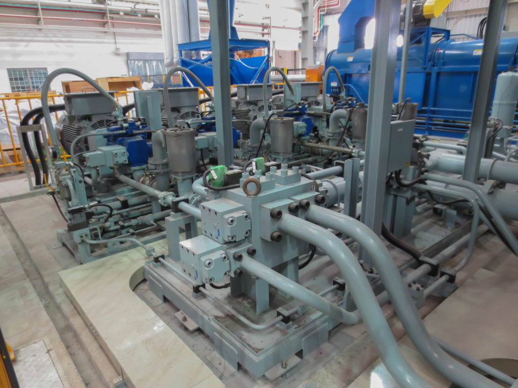
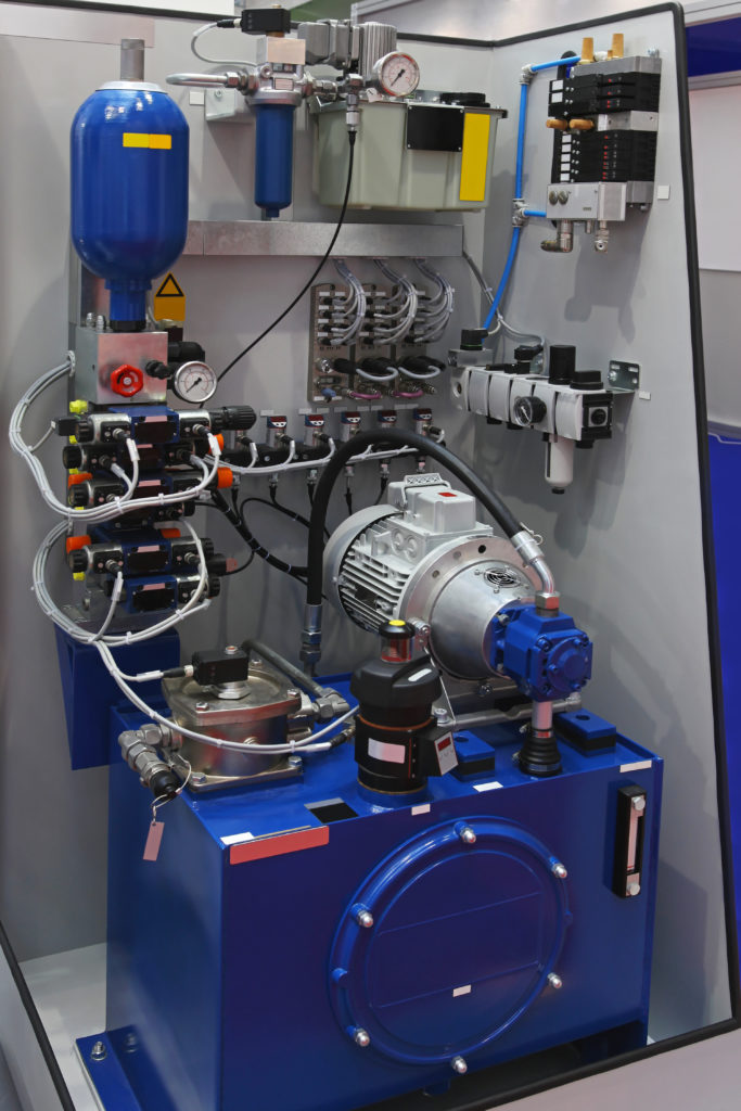
"Pascal"s Law" applies to confined liquids. Thus, in order for liquids to act hydraulically, they must be contained within a system. A hydraulic power pack or hydraulic power unit is a confined mechanical system that utilizes liquid hydraulically. Despite the fact that specific operating systems vary, all hydraulic power units share the same basic components. A reservoir, valves, a piping/tubing system, a pump, and actuators are examples of these components. Similarly, despite their versatility and adaptability, these mechanisms work together in related operating processes at the heart of all hydraulic power packs.
The hydraulic reservoir"s function is to hold a volume of liquid, transfer heat from the system, permit solid pollutants to settle, and aid in releasing moisture and air from the liquid.
Mechanical energy is changed to hydraulic energy by the hydraulic pump. This is accomplished through the movement of liquid, which serves as the transmission medium. All hydraulic pumps operate on the same basic principle of dispensing fluid volume against a resistive load or pressure.
Hydraulic valves are utilized to start, stop, and direct liquid flow in a system. Hydraulic valves are made of spools or poppets and can be actuated hydraulically, pneumatically, manually, electrically, or mechanically.
The end result of Pascal"s law is hydraulic actuators. This is the point at which hydraulic energy is transformed back to mechanical energy. This can be accomplished by using a hydraulic cylinder to transform hydraulic energy into linear movement and work or a hydraulic motor to transform hydraulic energy into rotational motion and work. Hydraulic motors and hydraulic cylinders, like hydraulic pumps, have various subtypes, each meant for specific design use.
The essence of hydraulics can be found in a fundamental physical fact: fluids are incompressible. (As a result, fluids more closely resemble solids than compressible gasses) The incompressible essence of fluid allows it to transfer force and speed very efficiently. This fact is summed up by a variant of "Pascal"s Principle," which states that virtually all pressure enforced on any part of a fluid is transferred to every other part of the fluid. This scientific principle states, in other words, that pressure applied to a fluid transmits equally in all directions.
Furthermore, the force transferred through a fluid has the ability to multiply as it moves. In a slightly more abstract sense, because fluids are incompressible, pressurized fluids should keep a consistent pressure just as they move. Pressure is defined mathematically as a force acting per particular area unit (P = F/A). A simplified version of this equation shows that force is the product of area and pressure (F = P x A). Thus, by varying the size or area of various parts inside a hydraulic system, the force acting inside the pump can be adjusted accordingly (to either greater or lesser). The need for pressure to remain constant is what causes force and area to mirror each other (on the basis of either shrinking or growing). A hydraulic system with a piston five times larger than a second piston can demonstrate this force-area relationship. When a force (e.g., 50lbs) is exerted on the smaller piston, it is multiplied by five (e.g., 250 lbs) and transmitted to the larger piston via the hydraulic system.
Hydraulics is built on fluids’ chemical properties and the physical relationship between pressure, area, and force. Overall, hydraulic applications allow human operators to generate and exert immense mechanical force with little to no physical effort. Within hydraulic systems, both oil and water are used to transmit power. The use of oil, on the other hand, is far more common, owing in part to its extremely incompressible nature.
Pressure relief valves prevent excess pressure by regulating the actuators’ output and redirecting liquid back to the reservoir when necessary. Directional control valves are used to change the size and direction of hydraulic fluid flow.
While hydraulic power transmission is remarkably useful in a wide range of professional applications, relying solely on one type of power transmission is generally unwise. On the contrary, the most efficient strategy is to combine a wide range of power transmissions (pneumatic, hydraulic, mechanical, and electrical). As a result, hydraulic systems must be carefully embedded into an overall power transmission strategy for the specific commercial application. It is necessary to invest in locating trustworthy and skilled hydraulic manufacturers/suppliers who can aid in the development and implementation of an overall hydraulic strategy.
The intended use of a hydraulic pump must be considered when selecting a specific type. This is significant because some pumps may only perform one function, whereas others allow for greater flexibility.
The pump"s material composition must also be considered in the application context. The cylinders, pistons, and gears are frequently made of long-lasting materials like aluminum, stainless steel, or steel that can withstand the continuous wear of repeated pumping. The materials must be able to withstand not only the process but also the hydraulic fluids. Composite fluids frequently contain oils, polyalkylene glycols, esters, butanol, and corrosion inhibitors (though water is used in some instances). The operating temperature, flash point, and viscosity of these fluids differ.
In addition to material, manufacturers must compare hydraulic pump operating specifications to make sure that intended utilization does not exceed pump abilities. The many variables in hydraulic pump functionality include maximum operating pressure, continuous operating pressure, horsepower, operating speed, power source, pump weight, and maximum fluid flow. Standard measurements like length, rod extension, and diameter should be compared as well. Because hydraulic pumps are used in lifts, cranes, motors, and other heavy machinery, they must meet strict operating specifications.
It is critical to recall that the overall power generated by any hydraulic drive system is influenced by various inefficiencies that must be considered in order to get the most out of the system. The presence of air bubbles within a hydraulic drive, for example, is known for changing the direction of the energy flow inside the system (since energy is wasted on the way to the actuators on bubble compression). Using a hydraulic drive system requires identifying shortfalls and selecting the best parts to mitigate their effects. A hydraulic pump is the "generator" side of a hydraulic system that initiates the hydraulic procedure (as opposed to the "actuator" side that completes the hydraulic procedure). Regardless of disparities, all hydraulic pumps are responsible for displacing liquid volume and transporting it to the actuator(s) from the reservoir via the tubing system. Some form of internal combustion system typically powers pumps.
While the operation of hydraulic pumps is normally the same, these mechanisms can be split into basic categories. There are two types of hydraulic pumps to consider: gear pumps and piston pumps. Radial and axial piston pumps are types of piston pumps. Axial pumps produce linear motion, whereas radial pumps can produce rotary motion. The gear pump category is further subdivided into external gear pumps and internal gear pumps.
Each type of hydraulic pump, regardless of piston or gear, is either double-action or single-action. Single-action pumps can only pull, push, or lift in one direction, while double-action pumps can pull, push, or lift in multiple directions.
Vane pumps are positive displacement pumps that maintain a constant flow rate under varying pressures. It is a pump that self-primes. It is referred to as a "vane pump" because the effect of the vane pressurizes the liquid.
This pump has a variable number of vanes mounted onto a rotor that rotates within the cavity. These vanes may be variable in length and tensioned to maintain contact with the wall while the pump draws power. The pump also features a pressure relief valve, which prevents pressure rise inside the pump from damaging it.
Internal gear pumps and external gear pumps are the two main types of hydraulic gear pumps. Pumps with external gears have two spur gears, the spurs of which are all externally arranged. Internal gear pumps also feature two spur gears, and the spurs of both gears are internally arranged, with one gear spinning around inside the other.
Both types of gear pumps deliver a consistent amount of liquid with each spinning of the gears. Hydraulic gear pumps are popular due to their versatility, effectiveness, and fairly simple design. Furthermore, because they are obtainable in a variety of configurations, they can be used in a wide range of consumer, industrial, and commercial product contexts.
Hydraulic ram pumps are cyclic machines that use water power, also referred to as hydropower, to transport water to a higher level than its original source. This hydraulic pump type is powered solely by the momentum of moving or falling water.
Ram pumps are a common type of hydraulic pump, especially among other types of hydraulic water pumps. Hydraulic ram pumps are utilized to move the water in the waste management, agricultural, sewage, plumbing, manufacturing, and engineering industries, though only about ten percent of the water utilized to run the pump gets to the planned end point.
Despite this disadvantage, using hydropower instead of an external energy source to power this kind of pump makes it a prominent choice in developing countries where the availability of the fuel and electricity required to energize motorized pumps is limited. The use of hydropower also reduces energy consumption for industrial factories and plants significantly. Having only two moving parts is another advantage of the hydraulic ram, making installation fairly simple in areas with free falling or flowing water. The water amount and the rate at which it falls have an important effect on the pump"s success. It is critical to keep this in mind when choosing a location for a pump and a water source. Length, size, diameter, minimum and maximum flow rates, and speed of operation are all important factors to consider.
Hydraulic water pumps are machines that move water from one location to another. Because water pumps are used in so many different applications, there are numerous hydraulic water pump variations.
Water pumps are useful in a variety of situations. Hydraulic pumps can be used to direct water where it is needed in industry, where water is often an ingredient in an industrial process or product. Water pumps are essential in supplying water to people in homes, particularly in rural residences that are not linked to a large sewage circuit. Water pumps are required in commercial settings to transport water to the upper floors of high rise buildings. Hydraulic water pumps in all of these situations could be powered by fuel, electricity, or even by hand, as is the situation with hydraulic hand pumps.
Water pumps in developed economies are typically automated and powered by electricity. Alternative pumping tools are frequently used in developing economies where dependable and cost effective sources of electricity and fuel are scarce. Hydraulic ram pumps, for example, can deliver water to remote locations without the use of electricity or fuel. These pumps rely solely on a moving stream of water’s force and a properly configured number of valves, tubes, and compression chambers.
Electric hydraulic pumps are hydraulic liquid transmission machines that use electricity to operate. They are frequently used to transfer hydraulic liquid from a reservoir to an actuator, like a hydraulic cylinder. These actuation mechanisms are an essential component of a wide range of hydraulic machinery.
There are several different types of hydraulic pumps, but the defining feature of each type is the use of pressurized fluids to accomplish a job. The natural characteristics of water, for example, are harnessed in the particular instance of hydraulic water pumps to transport water from one location to another. Hydraulic gear pumps and hydraulic piston pumps work in the same way to help actuate the motion of a piston in a mechanical system.
Despite the fact that there are numerous varieties of each of these pump mechanisms, all of them are powered by electricity. In such instances, an electric current flows through the motor, which turns impellers or other devices inside the pump system to create pressure differences; these differential pressure levels enable fluids to flow through the pump. Pump systems of this type can be utilized to direct hydraulic liquid to industrial machines such as commercial equipment like elevators or excavators.
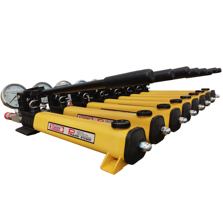
Hydraulic hand pumps are fluid transmission machines that utilize the mechanical force generated by a manually operated actuator. A manually operated actuator could be a lever, a toggle, a handle, or any of a variety of other parts. Hydraulic hand pumps are utilized for hydraulic fluid distribution, water pumping, and various other applications.
Hydraulic hand pumps may be utilized for a variety of tasks, including hydraulic liquid direction to circuits in helicopters and other aircraft, instrument calibration, and piston actuation in hydraulic cylinders. Hydraulic hand pumps of this type use manual power to put hydraulic fluids under pressure. They can be utilized to test the pressure in a variety of devices such as hoses, pipes, valves, sprinklers, and heat exchangers systems. Hand pumps are extraordinarily simple to use.
Each hydraulic hand pump has a lever or other actuation handle linked to the pump that, when pulled and pushed, causes the hydraulic liquid in the pump"s system to be depressurized or pressurized. This action, in the instance of a hydraulic machine, provides power to the devices to which the pump is attached. The actuation of a water pump causes the liquid to be pulled from its source and transferred to another location. Hydraulic hand pumps will remain relevant as long as hydraulics are used in the commerce industry, owing to their simplicity and easy usage.
12V hydraulic pumps are hydraulic power devices that operate on 12 volts DC supplied by a battery or motor. These are specially designed processes that, like all hydraulic pumps, are applied in commercial, industrial, and consumer places to convert kinetic energy into beneficial mechanical energy through pressurized viscous liquids. This converted energy is put to use in a variety of industries.
Hydraulic pumps are commonly used to pull, push, and lift heavy loads in motorized and vehicle machines. Hydraulic water pumps may also be powered by 12V batteries and are used to move water out of or into the desired location. These electric hydraulic pumps are common since they run on small batteries, allowing for ease of portability. Such portability is sometimes required in waste removal systems and vehiclies. In addition to portable and compact models, options include variable amp hour productions, rechargeable battery pumps, and variable weights.
While non rechargeable alkaline 12V hydraulic pumps are used, rechargeable ones are much more common because they enable a continuous flow. More considerations include minimum discharge flow, maximum discharge pressure, discharge size, and inlet size. As 12V batteries are able to pump up to 150 feet from the ground, it is imperative to choose the right pump for a given use.
Air hydraulic pumps are hydraulic power devices that use compressed air to stimulate a pump mechanism, generating useful energy from a pressurized liquid. These devices are also known as pneumatic hydraulic pumps and are applied in a variety of industries to assist in the lifting of heavy loads and transportation of materials with minimal initial force.
Air pumps, like all hydraulic pumps, begin with the same components. The hydraulic liquids, which are typically oil or water-based composites, require the use of a reservoir. The fluid is moved from the storage tank to the hydraulic cylinder via hoses or tubes connected to this reservoir. The hydraulic cylinder houses a piston system and two valves. A hydraulic fluid intake valve allows hydraulic liquid to enter and then traps it by closing. The discharge valve is the point at which the high pressure fluid stream is released. Air hydraulic pumps have a linked air cylinder in addition to the hydraulic cylinder enclosing one end of the piston.
The protruding end of the piston is acted upon by a compressed air compressor or air in the cylinder. When the air cylinder is empty, a spring system in the hydraulic cylinder pushes the piston out. This makes a vacuum, which sucks fluid from the reservoir into the hydraulic cylinder. When the air compressor is under pressure, it engages the piston and pushes it deeper into the hydraulic cylinder and compresses the liquids. This pumping action is repeated until the hydraulic cylinder pressure is high enough to forcibly push fluid out through the discharge check valve. In some instances, this is connected to a nozzle and hoses, with the important part being the pressurized stream. Other uses apply the energy of this stream to pull, lift, and push heavy loads.
Hydraulic piston pumps transfer hydraulic liquids through a cylinder using plunger-like equipment to successfully raise the pressure for a machine, enabling it to pull, lift, and push heavy loads. This type of hydraulic pump is the power source for heavy-duty machines like excavators, backhoes, loaders, diggers, and cranes. Piston pumps are used in a variety of industries, including automotive, aeronautics, power generation, military, marine, and manufacturing, to mention a few.
Hydraulic piston pumps are common due to their capability to enhance energy usage productivity. A hydraulic hand pump energized by a hand or foot pedal can convert a force of 4.5 pounds into a load-moving force of 100 pounds. Electric hydraulic pumps can attain pressure reaching 4,000 PSI. Because capacities vary so much, the desired usage pump must be carefully considered. Several other factors must also be considered. Standard and custom configurations of operating speeds, task-specific power sources, pump weights, and maximum fluid flows are widely available. Measurements such as rod extension length, diameter, width, and height should also be considered, particularly when a hydraulic piston pump is to be installed in place of a current hydraulic piston pump.
Hydraulic clutch pumps are mechanisms that include a clutch assembly and a pump that enables the user to apply the necessary pressure to disengage or engage the clutch mechanism. Hydraulic clutches are crafted to either link two shafts and lock them together to rotate at the same speed or detach the shafts and allow them to rotate at different speeds as needed to decelerate or shift gears.
Hydraulic pumps change hydraulic energy to mechanical energy. Hydraulic pumps are particularly designed machines utilized in commercial, industrial, and residential areas to generate useful energy from different viscous liquids pressurization. Hydraulic pumps are exceptionally simple yet effective machines for moving fluids. "Hydraulic" is actually often misspelled as "Hydralic". Hydraulic pumps depend on the energy provided by hydraulic cylinders to power different machines and mechanisms.
There are several different types of hydraulic pumps, and all hydraulic pumps can be split into two primary categories. The first category includes hydraulic pumps that function without the assistance of auxiliary power sources such as electric motors and gas. These hydraulic pump types can use the kinetic energy of a fluid to transfer it from one location to another. These pumps are commonly called ram pumps. Hydraulic hand pumps are never regarded as ram pumps, despite the fact that their operating principles are similar.
The construction, excavation, automotive manufacturing, agriculture, manufacturing, and defense contracting industries are just a few examples of operations that apply hydraulics power in normal, daily procedures. Since hydraulics usage is so prevalent, hydraulic pumps are unsurprisingly used in a wide range of machines and industries. Pumps serve the same basic function in all contexts where hydraulic machinery is used: they transport hydraulic fluid from one location to another in order to generate hydraulic energy and pressure (together with the actuators).
Elevators, automotive brakes, automotive lifts, cranes, airplane flaps, shock absorbers, log splitters, motorboat steering systems, garage jacks and other products use hydraulic pumps. The most common application of hydraulic pumps in construction sites is in big hydraulic machines and different types of "off-highway" equipment such as excavators, dumpers, diggers, and so on. Hydraulic systems are used in other settings, such as offshore work areas and factories, to power heavy machinery, cut and bend material, move heavy equipment, and so on.
Fluid’s incompressible nature in hydraulic systems allows an operator to make and apply mechanical power in an effective and efficient way. Practically all force created in a hydraulic system is applied to the intended target.
Because of the relationship between area, pressure, and force (F = P x A), modifying the force of a hydraulic system is as simple as changing the size of its components.
Hydraulic systems can transfer energy on an equal level with many mechanical and electrical systems while being significantly simpler in general. A hydraulic system, for example, can easily generate linear motion. On the contrary, most electrical and mechanical power systems need an intermediate mechanical step to convert rotational motion to linear motion.
Hydraulic systems are typically smaller than their mechanical and electrical counterparts while producing equivalents amounts of power, providing the benefit of saving physical space.
Hydraulic systems can be used in a wide range of physical settings due to their basic design (a pump attached to actuators via some kind of piping system). Hydraulic systems could also be utilized in environments where electrical systems would be impractical (for example underwater).
By removing electrical safety hazards, using hydraulic systems instead of electrical power transmission improves relative safety (for example explosions, electric shock).
The amount of power that hydraulic pumps can generate is a significant, distinct advantage. In certain cases, a hydraulic pump could generate ten times the power of an electrical counterpart. Some hydraulic pumps (for example, piston pumps) cost more than the ordinary hydraulic component. These drawbacks, however, can be mitigated by the pump"s power and efficiency. Despite their relatively high cost, piston pumps are treasured for their strength and capability to transmit very viscous fluids.
Handling hydraulic liquids is messy, and repairing leaks in a hydraulic pump can be difficult. Hydraulic liquid that leaks in hot areas may catch fire. Hydraulic lines that burst may cause serious injuries. Hydraulic liquids are corrosive as well, though some are less so than others. Hydraulic systems need frequent and intense maintenance. Parts with a high factor of precision are frequently required in systems. If the power is very high and the pipeline cannot handle the power transferred by the liquid, the high pressure received by the liquid may also cause work accidents.
Even though hydraulic systems are less complex than electrical or mechanical systems, they are still complex systems that should be handled with caution. Avoiding physical contact with hydraulic systems is an essential safety precaution when engaging with them. Even when a hydraulic machine is not in use, active liquid pressure within the system can be a hazard.
Inadequate pumps can cause mechanical failure in the place of work that can have serious and costly consequences. Although pump failure has historically been unpredictable, new diagnostic technology continues to improve on detecting methods that previously relied solely on vibration signals. Measuring discharge pressures enables manufacturers to forecast pump wear more accurately. Discharge sensors are simple to integrate into existing systems, increasing the hydraulic pump"s safety and versatility.
Hydraulic pumps are devices in hydraulic systems that move hydraulic fluid from point to point, initiating hydraulic power production. They are an important device overall in the hydraulics field, a special kind of power transmission that controls the energy which moving fluids transmit while under pressure and change into mechanical energy. Hydraulic pumps are divided into two categories namely gear pumps and piston pumps. Radial and axial piston pumps are types of piston pumps. Axial pumps produce linear motion, whereas radial pumps can produce rotary motion. The construction, excavation, automotive manufacturing, agriculture, manufacturing, and defense contracting industries are just a few examples of operations that apply hydraulics power in normal, daily procedures.

This website is using a security service to protect itself from online attacks. The action you just performed triggered the security solution. There are several actions that could trigger this block including submitting a certain word or phrase, a SQL command or malformed data.

With important work to do and limited resources, you can’t waste time and money on broken hydraulic pumps. That’s why the experts at CB HYMAC work tirelessly to provide you with affordable, around-the-clock hydraulic repair to a number of different products.
Thanks to modern technology, you can save on operational expenses and reduce downtime when you opt to repair your hydraulic component rather than replace it. However, repairing units involves more than just cleaning, flushing, regrinding, and reassembling the parts. Each hydraulic component is different and requires a unique approach for an effective result.
Dynamic Products: A dynamic product is one that needs continuous functionality like a hydraulic pump. Because hydraulic pumps need to run non-stop — even at idle speed — it’s more common for its components to experience wear and tear, especially in the mating parts. These often need to be replaced or repaired more often than other hydraulic equipment. The lifespan of a dynamic product like a hydraulic pump and its components depends on its duty cycle, design, and typical application.
Intermittent Dynamic: The opposite of a dynamic product, an intermittent dynamic unit is not required to constantly run in the system. The most common examples of an intermittent product include hydraulic motors, direction valves, and servo proportional valves. When not in use, these intermittent dynamic products are lowly idling or not operational. Intermittent dynamic units — due to their lower functionality requirements — do not wear and break as quickly as dynamic products.
Static Hydraulic: Pressure, flow, sequence, and check valves are the most common examples of a static hydraulic component. These items have internal functions that work in an open-and-close function which has little operational wear and tear and has a longer lifespan than both intermittent dynamic and dynamic products.
When you have a hydraulic product that unexpectedly breaks, you have to determine whether repairing, rebuilding, or remanufacturing is the most practical and economical solution for the best short and long-term results and equipment performance. To decide which approach is best for your situation, it’s best to understand the definition and expectations associated with each approach.
Repairing: With repairs, a technician is simply attempting to restore the condition of an old or failed part so it performs close to its original version. The most effective repairs are performed on pumps, motors, valves, and controls. For other equipment, repairs will likely not restore full, peak functionality.
Rebuilding: During a rebuilding process, damaged, inefficient parts are identified. From there, the entire component is fully dismantled then put back together with new or remanufactured parts. Once a hydraulic component has been rebuilt, it undergoes a thorough testing process and meets the specific requirements of newly built equipment. Hydraulic pumps and motors are ideal candidates for rebuilding procedures.
Remanufacturing: The remanufacturing process is divided into two different processes — manufacturing the existing core or reverse engineering. When working with the existing core, original parts are reworked to attempt restoring them to their original condition, then rebuilt on to the core. Improved, or reverse engineering, components are new and rebuilding components based on the dimensions of the original part.
CB HYMAC is a division of Cleveland Brothers, your local certified Cat® dealership. This means we can provide a number of quality services like hydraulic pump repairs and rebuilds certified to official Cat standards. We have a better grasp of Cat equipment and how it works than anyone else in the business. This grants us the capability to provide hydraulic pump rebuilds for both Caterpillar® pumps and those built by other leading Allied manufacturers.
Hammer rebuilds:To decrease repair time, we use a state-of-the-art hammer pit and a patented hammer test bench for a more thorough visual inspection and above-average testing performance.
CB HYMAC is officially recognized as a Cat Component Rebuild Center (CRC), and we use authentic Cat parts whenever applicable. We have no trouble quickly sourcing hard-to-find replacements for your equipment when a part wears out or stops working. Because we understand how much even a little downtime can affect your business, we have perfected a repair speed of 30 minutes or less to build, certify, clean and cap your hoses. We offer power lapping and power honing, and our 400 horsepower hydraulic pump test bench can reach 2,500 RPM or a 200-gallon flow.
At CB HYMAC, we utilize the Cleveland Brothers network with convenient locations throughout Pennsylvania and Northern West Virginia in order to receive your pump and motor. We will coordinate pick up from the location nearest you to get your pump and motor to our hydraulic shop in central Pennsylvania. Contact us today to learn more about our hydraulic pump repair parts and services and schedule your rebuild to keep your business thriving.

Hydraulic pumps are used in hydraulic drive systems and can be hydrostatic or hydrodynamic. A hydraulic pump is a mechanical source of power that converts mechanical power into hydraulic energy (hydrostatic energy i.e. flow, pressure). It generates flow with enough power to overcome pressure induced by the load at the pump outlet. When a hydraulic pump operates, it creates a vacuum at the pump inlet, which forces liquid from the reservoir into the inlet line to the pump and by mechanical action delivers this liquid to the pump outlet and forces it into the hydraulic system.
Hydrostatic pumps are positive displacement pumps while hydrodynamic pumps can be fixed displacement pumps, in which the displacement (flow through the pump per rotation of the pump) cannot be adjusted, or variable displacement pumps, which have a more complicated construction that allows the displacement to be adjusted. Hydrodynamic pumps are more frequent in day-to-day life. Hydrostatic pumps of various types all work on the principle of Pascal"s law.
Gear pumps (with external teeth) (fixed displacement) are simple and economical pumps. The swept volume or displacement of gear pumps for hydraulics will be between about 1 to 200 milliliters. They have the lowest volumetric efficiency (η
A rotary vane pump is a positive-displacement pump that consists of vanes mounted to a rotor that rotates inside a cavity. In some cases these vanes can have variable length and/or be tensioned to maintain contact with the walls as the pump rotates. A critical element in vane pump design is how the vanes are pushed into contact with the pump housing, and how the vane tips are machined at this very point. Several type of "lip" designs are used, and the main objective is to provide a tight seal between the inside of the housing and the vane, and at the same time to minimize wear and metal-to-metal contact. Forcing the vane out of the rotating centre and towards the pump housing is accomplished using spring-loaded vanes, or more traditionally, vanes loaded hydrodynamically (via the pressurized system fluid).
Screw pumps (fixed displacement) consist of two Archimedes" screws that intermesh and are enclosed within the same chamber. These pumps are used for high flows at relatively low pressure (max 100 bars (10,000 kPa)).ball valves
The major problem of screw pumps is that the hydraulic reaction force is transmitted in a direction that"s axially opposed to the direction of the flow.
Bent axis pumps, axial piston pumps and motors using the bent axis principle, fixed or adjustable displacement, exists in two different basic designs. The Thoma-principle (engineer Hans Thoma, Germany, patent 1935) with max 25 degrees angle and the Wahlmark-principle (Gunnar Axel Wahlmark, patent 1960) with spherical-shaped pistons in one piece with the piston rod, piston rings, and maximum 40 degrees between the driveshaft centerline and pistons (Volvo Hydraulics Co.). These have the best efficiency of all pumps. Although in general, the largest displacements are approximately one litre per revolution, if necessary a two-liter swept volume pump can be built. Often variable-displacement pumps are used so that the oil flow can be adjusted carefully. These pumps can in general work with a working pressure of up to 350–420 bars in continuous work.
By using different compensation techniques, the variable displacement type of these pumps can continuously alter fluid discharge per revolution and system pressure based on load requirements, maximum pressure cut-off settings, horsepower/ratio control, and even fully electro proportional systems, requiring no other input than electrical signals. This makes them potentially hugely power saving compared to other constant flow pumps in systems where prime mover/diesel/electric motor rotational speed is constant and required fluid flow is non-constant.
A radial piston pump is a form of hydraulic pump. The working pistons extend in a radial direction symmetrically around the drive shaft, in contrast to the axial piston pump.

Tokyo, November 8, 2010 — Kawasaki Heavy Industries, Ltd. announced today that Flutek Co., Ltd., Kawasaki’s Korean subsidiary specializing in hydraulic equipment production, sales and services, has expanded its production plant that manufactures hydraulic pumps for construction machinery.
In April 2003, Kawasaki acquired a controlling interest in Flutek with an eye to boosting its hydraulic equipment business operations in Korea. Kawasaki had long provided technical assistance to Flutek as a partner and distributer of its hydraulic products. Since coming under the corporate umbrella, Flutek has served as Kawasaki’s production, sales and customer service base in Korea. The expansion of Flutek’s production plant is designed to meet the growing Korean market demand for hydraulic pumps used in construction machinery.
The new production facility has been constructed on the premises of Flutek’s Uiryeong Plant, located 60 km northeast of Changwon City. Boasting a total area of 13,200 m2 with a floor area of 7,600 m2, the facility is designed specifically for the production of construction machinery hydraulic pumps. Equipped with new manufacturing equipment as well as a hydraulic pump assembly line transferred from Flutek’s Changwon Plant, the expanded Uiryeong Plant is moving ahead with knockdown production of hydraulic pumps using core parts supplied by Kawasaki’s Nishi-Kobe Works. The addition of the new manufacturing facility has doubled the production capacity of the hydraulic pump plant.
Today construction machinery manufacturers across Korea are gearing up production of hydraulic excavators. They have set their sights on the Chinese market where rapid economic growth is fueling a need for greater infrastructure development. While demand for hydraulic construction machinery equipment is rising in Korea, the Chinese hydraulic excavator market has now become the largest in the world. Continued growth over the medium- to long-term is expected to be spurred on by ongoing infrastructure improvements to irrigation, gas, electricity and transportation networks in China"s underdeveloped northeastern and inland regions.
Kawasaki is continuing to leverage the latest developments in technology with the aim of providing highly reliable, high-performance products to the ever-expanding global hydraulic equipment market. Driven by a deep commitment to improve after-sales and service capabilities, Kawasaki is bringing customer satisfaction to new heights.

Drain the cylinder. In order to drain the cylinder retract and extend the cylinder until all the fluid is removed. The fluid will exit the hoses removed in step 1.
While you have the reservoir off, use a mild parts cleaner to clean the filters and the inside of the reservoir. Mild parts cleaner can be purchased at your local auto parts store.
Pull the valve out of the pump and clean with parts cleaner as well, flushing the block. The cleaner will flow out of the tubes into your collection bucket.
Reassemble pump, reconnect hoses, and fill the reservoir with AW46 (hydraulic fluid) or Dexron III (automatic transmission fluid) and purge the system until it’s full. Be sure NOT to mix the two fluids. Only use one type.
First, Make sure your solenoid is properly grounded. To ground the solenoid, run a small 14 gauge ground wire from the ground on the pump to the screw mounting the solenoid to the motor.
Using a jumper wire, (14 gauge wire 10” long with alligator clips on both ends is easiest) jump from the 12V terminal on the solenoid to the activator post (the small post). You should hear a faint click.
With a 12V test light, check to see if you have 12V on the copper terminal that connects the solenoid to the motor (usually looking from the rear the copper terminal on the right). If you do have 12V, the solenoid is good, if not the solenoid needs to be replaced.
Step 3. To lower your spears, you will need two wires. Both wires will connect to the hot post on your solenoid. The end of one wire needs to connect to the plastic coil on the side of your pump.
Step 4. Next touch the other wire to the small actuator post on your solenoid. If your spears raise and lower properly, you need to replace your remote.
Step 3.Take a non-magnetic screwdriver or other metal tool and attempt to stick it to the coil. If the coil is working (magnetized) the metal tool will stick to the end of the coil. If it is not working the magnet is not getting a charge (magnetizing) and the tool will not stick to the coil.
SPX FLOW provides several hydraulic tools and equipment specially designed for applications in the railroad industry. SPX FLOW brand, Rail Systems, manufactures switching systems and crossing barriers for the UK and international markets. With a dedicated team of engineers, SPX FLOW Rail Systems designs point operating systems to meet the demands for the international rail operations for both conventional and high-speed applications. All manufacturing takes place at the Dagenham, UK facility by highly trained personnel with a long history in the Rail Industry.
SPX FLOW brand Power Team offers the railroad edition of a universal axle journal roller bearing puller/installer for removing and installing axle journal roller bearings. The PG Series Rail Stressing Power Pack was developed specifically for opening rail-stressing jacks. Many other Power Team hydraulic solutions can be used in the rail industry in roles that require lifting, pushing, pulling and more. Included is a wide range of hydraulic and electric pumps and jacks for use in track maintenance, and hydraulic rams and portable high-tonnage air and portable jacks for use in boxcar repair.
Power Team brand offers the railroad edition of a universal axle journal roller bearing puller/installer for removing and installing axle journal roller bearings. The PG Series Rail Stressing Power Pack was developed specifically for opening rail-stressing jacks. Many other Power Team hydraulic solutions can be used in the rail industry in roles that require lifting, pushing, pulling and more.
Rail Systems manufactures switching systems and crossing barriers for the UK and international markets. With a dedicated team of engineers, SPX FLOW Rail Systems designs point operating systems to meet the demands for the international rail operations for both conventional and high-speed applications. All manufacturing takes place at the Dagenham, UK facility by highly trained personnel with a long history in the Rail Industry.


 8613371530291