
where is the hydraulic pump on a tractor free sample

Over the years, revolutionary advancements have been instigated in the tractor control systems’ field. These changes are primarily attributed to integrating various hydraulic inventions in the tipping trailer, braking system, implementing control structure, and steering to enhance this machinery’s optimum functionality. Hydraulic flow and pressure can be translated to motion and forces that enhance a tractor’s capacity to execute tasks that operators cannot perform manually or physically (Gannon, 2017). This paper provides a comprehensive discussion of tractor hydraulics and highlights the benefits of this particular technology.
There are two forms of hydraulic systems: the open- and closed-center structures. The latter is typical in modern-day farm equipment; this includes most tractor models. When in neutral, this system’s closed center valve obstructs oil flow from the pump. This fluid travels to an accumulator, which typically stores it under pressure. The valves also block fluid flow via the center when the hydraulic is in the aforementioned state. A variable flow pump also halts its operation following the closure of the valve. Open hydraulic structures were commonly used in most of the preliminary tractors. When in neutral, this system’s open-center valves link all lines back to the reservoir, directly bypassing the pump, which is always in operation, fostering the constant flow of oil without accumulating pressure. Valves also allow the flow of fluid through the center and into the reservoir during this particular.
Hydraulic oil, particularly non-pressurized fluid, is usually stored in the reservoir. According to Moinfar and Shahgholi (2018), reservoirs are usually vented towards the atmosphere to acclimatize the changing levels of oil. The air vent is fitted with filters to impede the entry of dust or dirt into the reservoir. The reservoir’s metallic walls enhance the cooling process of the fluid by improving the outflow of heat. The decreased pressure within this structure also gives room for dissolved or trapped air to escape from the hydraulic fluid. A sufficient surface area is also essential to foster the dispersal of heat.
JIC and NPTF fittings prevent hydraulic components’ port leakage. NPTF taper pipe threads hinder seepage by using the male-to-female resistance thread taper. On the other hand, JICs sue O-ring (Moinfar & Shahgholi, 2018). The brake hydraulic system’s components are usually joined using hoses and lines. The latter connects the hydraulic system’s stationary parts while hoses consolidate in motion. The hose, tubing, or pipe’s size is crucial (Moinfar & Shahgholi, 2018). If the hose’s size is minimal, the flow of oil increases rapidly, generating heat and causing the fluid to lose power. The cost and time for installing a large hose, on the other hand, can be too high.
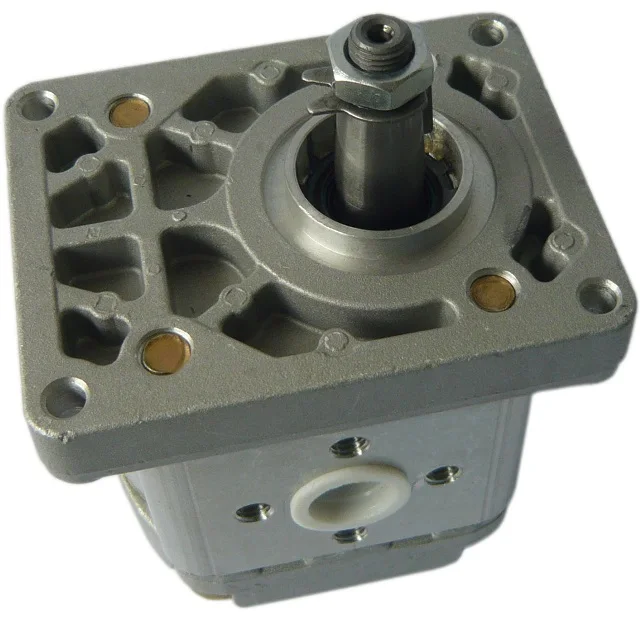
The hydraulic pump plays a crucial role in enhancing fluid transmission from the reservoir and towards the hydraulic system. This process elevates the fluid’s energy level by triggering significant surges in its pressure. A one-phase pump typically has a single flow rate and one maximal pressure. These pumps are usually attached to the PTO shaft or crankshaft on a farm tractor. These pumps are often fitted on manual loaders and backhoes. On the other hand, a two-step pump first generates high fluid volumes by enhancing the cylinder’s rapid in-and-out movements. In case of any form of resistance, an additional gear set is used to create high pressure for splitting and lifting. Nonetheless, the fluid’s volume will reduce significantly during this phase.
Examples of valves fitted in the hydraulic system of a tractor include the flow, pressure, and direction control valve. They function by stopping or impeding liquid or pressure flow and controlling the quantity, pressure, and direction of flow. The motor is located within the pump’s power source, i.e., the cylinder. The fluid with high-pressure levels exerts its action on the piston and rod located within the hydraulic cylinder (Gosaye et al., 2015). Each cylinder stroke converts or translates the power or pressure of the fluid into mechanical force or work. While the piston and rod extend, the reservoir’s oil levels decrease, and when these two devices retract, the fluid flows back to the reservoir.
The pressure is typically applied or exerted on one region of the piston in single-acting cylinders; thus, mechanical force occurs in a single direction only. The cylinder then assumes its initial position under the load’s weight. Contrarily, pressure may be exerted on both sides of the piston in double-acting cylinders. Consequently, work takes place in either direction. The fixed ends in welded cylinders are usually welded to increase the durability and strength for high-pressure functions. Four rods are typically used to hold tie-rod cylinders together.
The instigation of hydraulics triggered significant changes in the agricultural industry, especially concerning the manner and method of production. The adoption of this technology has triggered substantial reductions in the level of manual power or effort needed to perform farm-related activities both in terms of work animals and workers (“How Hydraulics Transformed,” 2019). The tractor has also been effective in decreasing the risks associated with farm-related injuries by minimizing the number of hours individuals spend working in agricultural fields. This invention has also helped restrict the downtime rate amid agricultural operations. Furthermore, it has been crucial in promoting personal and overall productivity and efficiency during practice.
Significant advancements in agricultural engineering, particularly in tractor hydraulics, have triggered farm-related practices’ efficacy and efficiency. The tractor hydraulic system has several components, including the reservoir, pump, and motor. Hydraulics foster a tractor operator’s capacity to execute tasks that demand substantial effort with an electrical switch flip or simple lever push, which, in turn, actuates the hydraulic circuit. Contemporary farming integrates the use of hydraulics for operations that were initially controlled by mechanical means.
Gosaye, C., Mengiste, Z., & Hailu, A. (2015). Evaluation of the compatibility of tractors and implements at Tendaho Sugar Estate. ARPN Journal of Science and Technology, 5(10), 476–483. Web.

Whether gear, vane, or piston pump, there may come a time when you have to replace your hydraulic pump. When your equipment isn’t working properly and you have narrowed the problem down to a hydraulic pump that needs to be replaced, what do you need to know?
The pump may simply be worn out—they do have a natural lifespan, as they are a wearable item in a hydraulic system. Although it is not possible to give an average lifespan given the different types of pumps and widely varying hours of operation; in general, you can expect many years of good operation from a hydraulic pump in most truck-mounted hydraulic systems. However, the life of a hydraulic pump might be much longer than what you are experiencing. Here are some questions you should ask:
Has the equipment been operating acceptably with this pump for a number of years without incident, and has the decline in performance been gradual over a longer period of time?
In this case, you’ll need to get the pump make and model number so that you can make sure that your replacement will be correct—either with an exact replacement or with another make that has the same operating specifications.
In any case, when replacing a failed hydraulic pump you will want to make sure to use this opportunity to also change out your hydraulic fluid (or at the very least use a filter cart and filter your oil). In the process of failing, your pump has introduced contaminants into your hydraulic system that you want to remove before they damage your new pump or any other hydraulic component. You will want to change your filter element(s) when you install your new pump, and then change it (them) out after a break-in period on your new pump.
If not, then let’s make sure there is not something else going on, or you may just find yourself replacing pumps frequently because the underlying problem hasn’t been addressed.
Input shaft is twisted/bcanroken: This occurs due to an extreme shock load to the pump. Typically, this happens when a relief valve is missing from the system, not functioning correctly, set to a much higher value than what the pump can withstand, or is too small for the system flow and thus cannot function correctly.
Shaft fretting:Fretting corrosion occurs under load in the presence of repeated relative surface motion, for example by vibration. Direct mount pump splines can be worn away. The solutions include:
Using larger pump and PTO shafts will not eliminate fretting, but may resolve the problem because of the increased metal available before the failure occurs.
Check to see that there is a sufficient amount of oil in the reservoir. Not just when the system is at rest, but also when all cylinders are extended to their maximum length or when all the components are running.
Make sure that the pump is able to get a good flow of oil from the reservoir—pumps are designed to have the oil feed pushed to the pump by gravity and atmospheric pressure, not by “sucking” oil. If the oil level in the reservoir is lower than the inlet of the pump, or the run too long or uphill, oil may not flow adequately to the pump. You can check if the pump is receiving oil adequately by using a vacuum gauge at the pump inlet. For a standard gear pump, at maximum operating RPM, the gauge should read a maximum of 5 inches HG. Larger numbers will damage a gear pump, and if you have a piston pump, the maximum number will be lower for good pump life.
Over pressurization: Pressure relief settings may have been adjusted or changed, and are now higher than what the pump can withstand without causing damage.
Pumps don’t produce pressure, they produce flow and are built to withstand pressure. When the system pressure exceeds the pump design, failure begins—either gradually or catastrophically.
When installing the new pump, back all the relief settings off. Then with the use of a pressure gauge T’d in at the pump outlet, gradually adjust the pressure relief setting until a cylinder or motor begins to move. Once the cylinder has reached the end of its stroke, gradually increase the pressure relief setting until reaching the max system pressure (which would be the pressure rating of the lowest rated component in the system). Sometimes, if a pump has been replaced and is larger than the original (produces more flow), the relief may not be able to allow all the flow being produced to escape back to tank. When that happens, the relief valve is “saturated” and the effect is the same as having no relief in the system. Pressures can reach levels much higher than the relief settings and components can be damaged or destroyed.
Contamination: Over time, the system oil has gotten dirty or contaminated and no longer is able to lubricate the pump, or is carrying contamination to the pump.
Make sure the oil is clean, the oil filer changed on schedule, and that there are no entry points for contamination like water, dust, or dirt from a reservoir filler cap that is unfiltered or missing, seals in motors or cylinders that are allowing contaminants in, etc.
New hoses can contain leftover bits of rubber and metal particles from the cutting and crimping process and should be cleaned out before installation.
Even new oil may be quite dirty if stored incorrectly, or exposed to dust and dirt. It’s always a good idea to use a filter cart and filter the system once it’s refilled with oil before turning on the system.
This website is using a security service to protect itself from online attacks. The action you just performed triggered the security solution. There are several actions that could trigger this block including submitting a certain word or phrase, a SQL command or malformed data.

Check that the electric motor is running. Although this is a simple concept, before you begin replacing parts, it’s critical that you make sure the electric motor is running. This can often be one of the easiest aspects to overlook, but it is necessary to confirm before moving forward.
Check that the pump shaft is rotating. Even though coupling guards and C-face mounts can make this difficult to confirm, it is important to establish if your pump shaft is rotating. If it isn’t, this could be an indication of a more severe issue, and this should be investigated immediately.
Check the oil level. This one tends to be the more obvious check, as it is often one of the only factors inspected before the pump is changed. The oil level should be three inches above the pump suction. Otherwise, a vortex can form in the reservoir, allowing air into the pump.
If the oil level is low, determine where the leak is in the system. Although this can be a difficult process, it is necessary to ensure your machines are performing properly. Leaks can be difficult to find.
What does the pump sound like when it is operating normally? Vane pumps generally are quieter than piston and gear pumps. If the pump has a high-pitched whining sound, it most likely is cavitating. If it has a knocking sound, like marbles rattling around, then aeration is the likely cause.
Cavitation is the formation and collapse of air cavities in the liquid. When the pump cannot get the total volume of oil it needs, cavitation occurs. Hydraulic oil contains approximately nine percent dissolved air. When the pump does not receive adequate oil volume at its suction port, high vacuum pressure occurs.
This dissolved air is pulled out of the oil on the suction side and then collapses or implodes on the pressure side. The implosions produce a very steady, high-pitched sound. As the air bubbles collapse, the inside of the pump is damaged.
While cavitation is a devastating development, with proper preventative maintenance practices and a quality monitoring system, early detection and deterrence remain attainable goals. UE System’s UltraTrak 850S CD pump cavitation sensor is a Smart Analog Sensor designed and optimized to detect cavitation on pumps earlier by measuring the ultrasound produced as cavitation starts to develop early-onset bubbles in the pump. By continuously monitoring the impact caused by cavitation, the system provides a simple, single value to trend and alert when cavitation is occurring.
The oil viscosity is too high. Low oil temperature increases the oil viscosity, making it harder for the oil to reach the pump. Most hydraulic systems should not be started with the oil any colder than 40°F and should not be put under load until the oil is at least 70°F.
Many reservoirs do not have heaters, particularly in the South. Even when heaters are available, they are often disconnected. While the damage may not be immediate, if a pump is continually started up when the oil is too cold, the pump will fail prematurely.
The suction filter or strainer is contaminated. A strainer is typically 74 or 149 microns in size and is used to keep “large” particles out of the pump. The strainer may be located inside or outside the reservoir. Strainers located inside the reservoir are out of sight and out of mind. Many times, maintenance personnel are not even aware that there is a strainer in the reservoir.
The suction strainer should be removed from the line or reservoir and cleaned a minimum of once a year. Years ago, a plant sought out help to troubleshoot a system that had already had five pumps changed within a single week. Upon closer inspection, it was discovered that the breather cap was missing, allowing dirty air to flow directly into the reservoir.
A check of the hydraulic schematic showed a strainer in the suction line inside the tank. When the strainer was removed, a shop rag was found wrapped around the screen mesh. Apparently, someone had used the rag to plug the breather cap opening, and it had then fallen into the tank. Contamination can come from a variety of different sources, so it pays to be vigilant and responsible with our practices and reliability measures.
The electric motor is driving the hydraulic pump at a speed that is higher than the pump’s rating. All pumps have a recommended maximum drive speed. If the speed is too high, a higher volume of oil will be needed at the suction port.
Due to the size of the suction port, adequate oil cannot fill the suction cavity in the pump, resulting in cavitation. Although this rarely happens, some pumps are rated at a maximum drive speed of 1,200 revolutions per minute (RPM), while others have a maximum speed of 3,600 RPM. The drive speed should be checked any time a pump is replaced with a different brand or model.
Every one of these devastating causes of cavitation threatens to cause major, irreversible damage to your equipment. Therefore, it’s not only critical to have proper, proactive practices in place, but also a monitoring system that can continuously protect your valuable assets, such as UE System’s UltraTrak 850S CD pump cavitation senor. These sensors regularly monitor the health of your pumps and alert you immediately if cavitation symptoms are present, allowing you to take corrective action before it’s too late.
Aeration is sometimes known as pseudo cavitation because air is entering the pump suction cavity. However, the causes of aeration are entirely different than that of cavitation. While cavitation pulls air out of the oil, aeration is the result of outside air entering the pump’s suction line.
Several factors can cause aeration, including an air leak in the suction line. This could be in the form of a loose connection, a cracked line, or an improper fitting seal. One method of finding the leak is to squirt oil around the suction line fittings. The fluid will be momentarily drawn into the suction line, and the knocking sound inside the pump will stop for a short period of time once the airflow path is found.
A bad shaft seal can also cause aeration if the system is supplied by one or more fixed displacement pumps. Oil that bypasses inside a fixed displacement pump is ported back to the suction port. If the shaft seal is worn or damaged, air can flow through the seal and into the pump’s suction cavity.
As mentioned previously, if the oil level is too low, oil can enter the suction line and flow into the pump. Therefore, always check the oil level with all cylinders in the retracted position.
If a new pump is installed and pressure will not build, the shaft may be rotating in the wrong direction. Some gear pumps can be rotated in either direction, but most have an arrow on the housing indicating the direction of rotation, as depicted in Figure 2.
Pump rotation should always be viewed from the shaft end. If the pump is rotated in the wrong direction, adequate fluid will not fill the suction port due to the pump’s internal design.
A fixed displacement pump delivers a constant volume of oil for a given shaft speed. A relief valve must be included downstream of the pump to limit the maximum pressure in the system.
After the visual and sound checks are made, the next step is to determine whether you have a volume or pressure problem. If the pressure will not build to the desired level, isolate the pump and relief valve from the system. This can be done by closing a valve, plugging the line downstream, or blocking the relief valve. If the pressure builds when this is done, there is a component downstream of the isolation point that is bypassing. If the pressure does not build up, the pump or relief valve is bad.
If the system is operating at a slower speed, a volume problem exists. Pumps wear over time, which results in less oil being delivered. While a flow meter can be installed in the pump’s outlet line, this is not always practical, as the proper fittings and adapters may not be available. To determine if the pump is badly worn and bypassing, first check the current to the electric motor. If possible, this test should be made when the pump is new to establish a reference. Electric motor horsepower is relative to the hydraulic horsepower required by the system.
For example, if a 50-GPM pump is used and the maximum pressure is 1,500 psi, a 50-hp motor will be required. If the pump is delivering less oil than when it was new, the current to drive the pump will drop. A 230-volt, 50-hp motor has an average full load rating of 130 amps. If the amperage is considerably lower, the pump is most likely bypassing and should be changed.
Figure 4.To isolate a fixed displacement pump and relief valve from the system, close a valve or plug the line downstream (left). If pressure builds, a component downstream of the isolation point is bypassing (right).
The most common type of variable displacement pump is the pressure-compensating design. The compensator setting limits the maximum pressure at the pump’s outlet port. The pump should be isolated as described for the fixed displacement pump.
If pressure does not build up, the relief valve or pump compensator may be bad. Prior to checking either component, perform the necessary lockout procedures and verify that the pressure at the outlet port is zero psi. The relief valve and compensator can then be taken apart and checked for contamination, wear, and broken springs.
Check the tank line temperature of the relief valve with a temperature gun or infrared camera. The tank line should be near ambient temperature. If the line is hot, the relief valve is either stuck partially open or is set too low.
Install a flow meter in the case drain line and check the flow rate. Most variable displacement pumps bypass one to three percent of the maximum pump volume through the case drain line. If the flow rate reaches 10 percent, the pump should be changed. Permanently installing a flow meter in the case drain line is an excellent reliability and troubleshooting tool.
Ensure the compensator is 200 psi above the maximum load pressure. If set too low, the compensator spool will shift and start reducing the pump volume when the system is calling for maximum volume.
Performing these recommended tests should help you make good decisions about the condition of your pumps or the cause of pump failures. If you change a pump, have a reason for changing it. Don’t just do it because you have a spare one in stock.
Conduct a reliability assessment on each of your hydraulic systems so when an issue occurs, you will have current pressure and temperature readings to consult.
Al Smiley is the president of GPM Hydraulic Consulting Inc., located in Monroe, Georgia. Since 1994, GPM has provided hydraulic training, consulting and reliability assessments to companies in t...
If you ended up on this page doing normal allowed operations, please contact our support at support@mdpi.com. Please include what you were doing when this page came up and the Ray ID & Your IP found at the

Tractor parts, manuals, books and more for the older (pre-1975) tractors. Our free Monthly Magazine is loaded with photos, exclusive articles, free classified ads, forums and more!
The unit is designed to look like front-mounted tractor weights but actually adds less than 150 lbs. to the front of the tractor. The unit holds a little over 5 gal. of hydraulic oil. A 9 gpm vane pump is embedded inside the reservoir.
Once installed, the tractor has hydraulic power whether or not the clutch is engaged. Most older model tractors have low or limited internal pump flow the hydraulics only work as long as the clutch is engaged.
"The 9gpm pump has enough flow to run most any combination of hydraulic applications, independent of the tractor"s internal hydraulics. A side benefit is having the reservoir on the front of the tractor to give added weight to the front. The unit is as wide as the tractor hood and extends about 8 in. past the grill," says Jackson.
He offers a wide range of hydraulic valves and remotes to match the system, which can be used for log splitters, dump trailers, grain augers, stump grinders, and even add-on power steering.
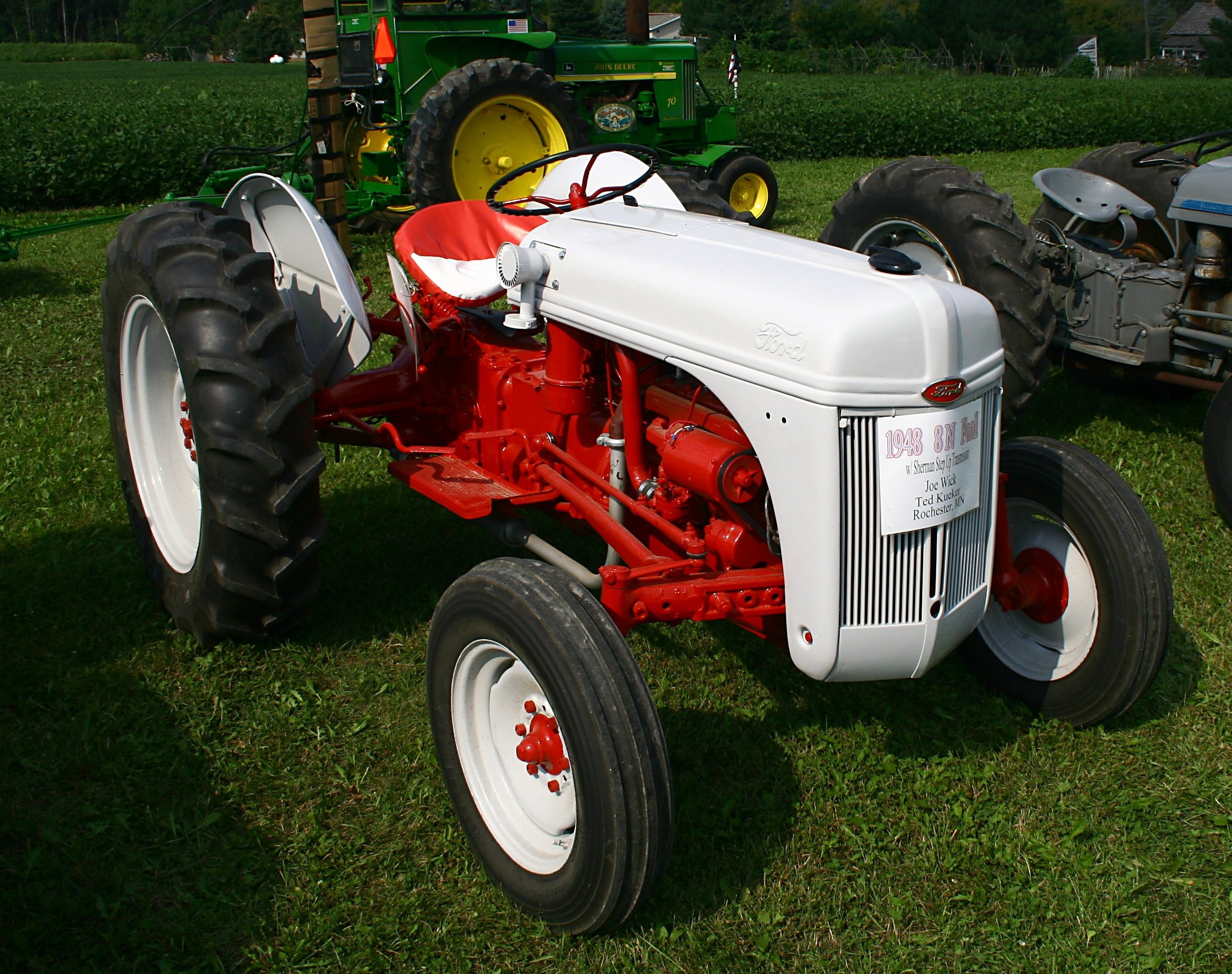
Inventor Roland Jackson is starting out with Fords (9N, 8N, 2N, NAA, 600 Series, 800 Series and early 1000 Series). However, he will soon be adding other models since the hydraulics are the same. Only the mounting brackets are different.
Add-On "Live Hydraulics" For Older Model Tractors TRACTORS Hydraulics 30-1-32 This new front-mounted hydraulic system, recently introduced by Jackson Power Steering, is designed to give older tractors a "live hydraulics" system that"s reliable, strong and trouble-free. The unit is designed to look like front-mounted tractor weights but actually adds less than 150 lbs. to the front of the tractor. The unit holds a little over 5 gal. of hydraulic oil. A 9 gpm vane pump is embedded inside the reservoir. Once installed, the tractor has hydraulic power whether or not the clutch is engaged. Most older model tractors have low or limited internal pump flow the hydraulics only work as long as the clutch is engaged. "The 9gpm pump has enough flow to run most any combination of hydraulic applications, independent of the tractor"s internal hydraulics. A side benefit is having the reservoir on the front of the tractor to give added weight to the front. The unit is as wide as the tractor hood and extends about 8 in. past the grill," says Jackson.He offers a wide range of hydraulic valves and remotes to match the system, which can be used for log splitters, dump trailers, grain augers, stump grinders, and even add-on power steering.Inventor Roland Jackson is starting out with Fords (9N, 8N, 2N, NAA, 600 Series, 800 Series and early 1000 Series). However, he will soon be adding other models since the hydraulics are the same. Only the mounting brackets are different.The kit includes the reservoir, embedded pump, mounting brackets, crankshaft drive kit, and instructions. Sells for $1,495 plus shipping.Contact: FARM SHOW Followup, Jackson Power Steering, Rt. 2, Box 220, Jetmore, Kan. 67854 (ph 620 357-6546; sales@jacksonpowersteering.com).
Hydraulic pumps are used in hydraulic drive systems and can be hydrostatic or hydrodynamic. A hydraulic pump is a mechanical source of power that converts mechanical power into hydraulic energy (hydrostatic energy i.e. flow, pressure). It generates flow with enough power to overcome pressure induced by the load at the pump outlet. When a hydraulic pump operates, it creates a vacuum at the pump inlet, which forces liquid from the reservoir into the inlet line to the pump and by mechanical action delivers this liquid to the pump outlet and forces it into the hydraulic system.
Hydrostatic pumps are positive displacement pumps while hydrodynamic pumps can be fixed displacement pumps, in which the displacement (flow through the pump per rotation of the pump) cannot be adjusted, or variable displacement pumps, which have a more complicated construction that allows the displacement to be adjusted. Hydrodynamic pumps are more frequent in day-to-day life. Hydrostatic pumps of various types all work on the principle of Pascal"s law.
Gear pumps (with external teeth) (fixed displacement) are simple and economical pumps. The swept volume or displacement of gear pumps for hydraulics will be between about 1 to 200 milliliters. They have the lowest volumetric efficiency (η
A rotary vane pump is a positive-displacement pump that consists of vanes mounted to a rotor that rotates inside a cavity. In some cases these vanes can have variable length and/or be tensioned to maintain contact with the walls as the pump rotates. A critical element in vane pump design is how the vanes are pushed into contact with the pump housing, and how the vane tips are machined at this very point. Several type of "lip" designs are used, and the main objective is to provide a tight seal between the inside of the housing and the vane, and at the same time to minimize wear and metal-to-metal contact. Forcing the vane out of the rotating centre and towards the pump housing is accomplished using spring-loaded vanes, or more traditionally, vanes loaded hydrodynamically (via the pressurized system fluid).
Screw pumps (fixed displacement) consist of two Archimedes" screws that intermesh and are enclosed within the same chamber. These pumps are used for high flows at relatively low pressure (max 100 bars (10,000 kPa)).ball valves
The major problem of screw pumps is that the hydraulic reaction force is transmitted in a direction that"s axially opposed to the direction of the flow.
Bent axis pumps, axial piston pumps and motors using the bent axis principle, fixed or adjustable displacement, exists in two different basic designs. The Thoma-principle (engineer Hans Thoma, Germany, patent 1935) with max 25 degrees angle and the Wahlmark-principle (Gunnar Axel Wahlmark, patent 1960) with spherical-shaped pistons in one piece with the piston rod, piston rings, and maximum 40 degrees between the driveshaft centerline and pistons (Volvo Hydraulics Co.). These have the best efficiency of all pumps. Although in general, the largest displacements are approximately one litre per revolution, if necessary a two-liter swept volume pump can be built. Often variable-displacement pumps are used so that the oil flow can be adjusted carefully. These pumps can in general work with a working pressure of up to 350–420 bars in continuous work.
By using different compensation techniques, the variable displacement type of these pumps can continuously alter fluid discharge per revolution and system pressure based on load requirements, maximum pressure cut-off settings, horsepower/ratio control, and even fully electro proportional systems, requiring no other input than electrical signals. This makes them potentially hugely power saving compared to other constant flow pumps in systems where prime mover/diesel/electric motor rotational speed is constant and required fluid flow is non-constant.
A radial piston pump is a form of hydraulic pump. The working pistons extend in a radial direction symmetrically around the drive shaft, in contrast to the axial piston pump.

A gear pump is a type of positive displacement (PD) pump. It moves a fluid by repeatedly enclosing a fixed volume using interlocking cogs or gears, transferring it mechanically using a cyclic pumping action. It delivers a smooth pulse-free flow proportional to the rotational speed of its gears.
Gear pumps use the actions of rotating cogs or gears to transfer fluids. The rotating element develops a liquid seal with the pump casing and creates suction at the pump inlet. Fluid, drawn into the pump, is enclosed within the cavities of its rotating gears and transferred to the discharge. There are two basic designs of gear pump: external and internal(Figure 1).
An external gear pump consists of two identical, interlocking gears supported by separate shafts. Generally, one gear is driven by a motor and this drives the other gear (the idler). In some cases, both shafts may be driven by motors. The shafts are supported by bearings on each side of the casing.
As the gears come out of mesh on the inlet side of the pump, they create an expanded volume. Liquid flows into the cavities and is trapped by the gear teeth as the gears continue to rotate against the pump casing.
No fluid is transferred back through the centre, between the gears, because they are interlocked. Close tolerances between the gears and the casing allow the pump to develop suction at the inlet and prevent fluid from leaking back from the discharge side (although leakage is more likely with low viscosity liquids).
An internal gear pump operates on the same principle but the two interlocking gears are of different sizes with one rotating inside the other. The larger gear (the rotor) is an internal gear i.e. it has the teeth projecting on the inside. Within this is a smaller external gear (the idler –only the rotor is driven) mounted off-centre. This is designed to interlock with the rotor such that the gear teeth engage at one point. A pinion and bushing attached to the pump casing holds the idler in position. A fixed crescent-shaped partition or spacer fills the void created by the off-centre mounting position of the idler and acts as a seal between the inlet and outlet ports.
As the gears come out of mesh on the inlet side of the pump, they create an expanded volume. Liquid flows into the cavities and is trapped by the gear teeth as the gears continue to rotate against the pump casing and partition.
Gear pumps are compact and simple with a limited number of moving parts. They are unable to match the pressure generated by reciprocating pumps or the flow rates of centrifugal pumps but offer higher pressures and throughputs than vane or lobe pumps. Gear pumps are particularly suited for pumping oils and other high viscosity fluids.
Of the two designs, external gear pumps are capable of sustaining higher pressures (up to 3000 psi) and flow rates because of the more rigid shaft support and closer tolerances. Internal gear pumps have better suction capabilities and are suited to high viscosity fluids, although they have a useful operating range from 1cP to over 1,000,000cP. Since output is directly proportional to rotational speed, gear pumps are commonly used for metering and blending operations. Gear pumps can be engineered to handle aggressive liquids. While they are commonly made from cast iron or stainless steel, new alloys and composites allow the pumps to handle corrosive liquids such as sulphuric acid, sodium hypochlorite, ferric chloride and sodium hydroxide.
External gear pumps can also be used in hydraulic power applications, typically in vehicles, lifting machinery and mobile plant equipment. Driving a gear pump in reverse, using oil pumped from elsewhere in a system (normally by a tandem pump in the engine), creates a hydraulic motor. This is particularly useful to provide power in areas where electrical equipment is bulky, costly or inconvenient. Tractors, for example, rely on engine-driven external gear pumps to power their services.
Gear pumps are self-priming and can dry-lift although their priming characteristics improve if the gears are wetted. The gears need to be lubricated by the pumped fluid and should not be run dry for prolonged periods. Some gear pump designs can be run in either direction so the same pump can be used to load and unload a vessel, for example.
The close tolerances between the gears and casing mean that these types of pump are susceptible to wear particularly when used with abrasive fluids or feeds containing entrained solids. However, some designs of gear pumps, particularly internal variants, allow the handling of solids. External gear pumps have four bearings in the pumped medium, and tight tolerances, so are less suited to handling abrasive fluids. Internal gear pumps are more robust having only one bearing (sometimes two) running in the fluid. A gear pump should always have a strainer installed on the suction side to protect it from large, potentially damaging, solids.
Generally, if the pump is expected to handle abrasive solids it is advisable to select a pump with a higher capacity so it can be operated at lower speeds to reduce wear. However, it should be borne in mind that the volumetric efficiency of a gear pump is reduced at lower speeds and flow rates. A gear pump should not be operated too far from its recommended speed.
For high temperature applications, it is important to ensure that the operating temperature range is compatible with the pump specification. Thermal expansion of the casing and gears reduces clearances within a pump and this can also lead to increased wear, and in extreme cases, pump failure.
Despite the best precautions, gear pumps generally succumb to wear of the gears, casing and bearings over time. As clearances increase, there is a gradual reduction in efficiency and increase in flow slip: leakage of the pumped fluid from the discharge back to the suction side. Flow slip is proportional to the cube of the clearance between the cog teeth and casing so, in practice, wear has a small effect until a critical point is reached, from which performance degrades rapidly.
Gear pumps continue to pump against a back pressure and, if subjected to a downstream blockage will continue to pressurise the system until the pump, pipework or other equipment fails. Although most gear pumps are equipped with relief valves for this reason, it is always advisable to fit relief valves elsewhere in the system to protect downstream equipment.
Internal gear pumps, operating at low speed, are generally preferred for shear-sensitive liquids such as foodstuffs, paint and soaps. The higher speeds and lower clearances of external gear designs make them unsuitable for these applications. Internal gear pumps are also preferred when hygiene is important because of their mechanical simplicity and the fact that they are easy to strip down, clean and reassemble.
Gear pumps are commonly used for pumping high viscosity fluids such as oil, paints, resins or foodstuffs. They are preferred in any application where accurate dosing or high pressure output is required. The output of a gear pump is not greatly affected by pressure so they also tend to be preferred in any situation where the supply is irregular.
A gear pump moves a fluid by repeatedly enclosing a fixed volume within interlocking cogs or gears, transferring it mechanically to deliver a smooth pulse-free flow proportional to the rotational speed of its gears. There are two basic types: external and internal. An external gear pump consists of two identical, interlocking gears supported by separate shafts. An internal gear pump has two interlocking gears of different sizes with one rotating inside the other.
Gear pumps are commonly used for pumping high viscosity fluids such as oil, paints, resins or foodstuffs. They are also preferred in applications where accurate dosing or high pressure output is required. External gear pumps are capable of sustaining higher pressures (up to 7500 psi) whereas internal gear pumps have better suction capabilities and are more suited to high viscosity and shear-sensitive fluids.

A: We can supply the sample if there is available sampes in stock,but we"d like to charge the sample cost and the customers should pay the shipping cost.


 8613371530291