
kelly bushing depth quotation
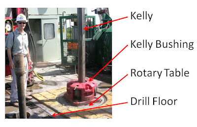
Kelly bushing is that elevated device positioned right on top of the rotary table and used to transmit torque from the rotary table to the kelly. The kelly bushing is designed to be the connection between the rotary table and the kelly. The kelly is a 4 or 6 sided steel pipe.
The purpose of the rotary table is to generate the rotary action (torque) and power necessary to rotate the drillstring and drill a well. The torque generated by the rotary table is useless if it is not transferred to the kelly (the drillstring is connected to the kelly).
Hence, through the kelly bushing the torque generated at the rotary table is transferred to the kelly. To achieve this connection, the inside profile of the kelly bushing matches the outer profile of the kelly so that the kelly fits or “sits” comfortably in the kelly bushing.
There are various designs for the kelly bushing including the split type, the pin-drive type and the square-drive type. Each of these designs has different ways in which they are connected and disconnected from the rotary table.
The internal diameter of the kelly bushing can be cut into the shape of a square (4-sided) or a hexagon (6-sided) depending on the outer shape of the kelly that will be used. The internals of a Kelly bushing is designed to resemble the outer shape of a Kelly just like the insides of a key lock is cut to exactly match the outer shape of the key.
The kelly bushing is not designed to hold tightly onto the Kelly; the kelly is still permitted to move up and down through the kelly bushing. This requirement is a must since drilling cannot progress if the kelly remains on a fixed spot. As the well is drilled deeper, the kelly also moves downward through the Kelly bushing.
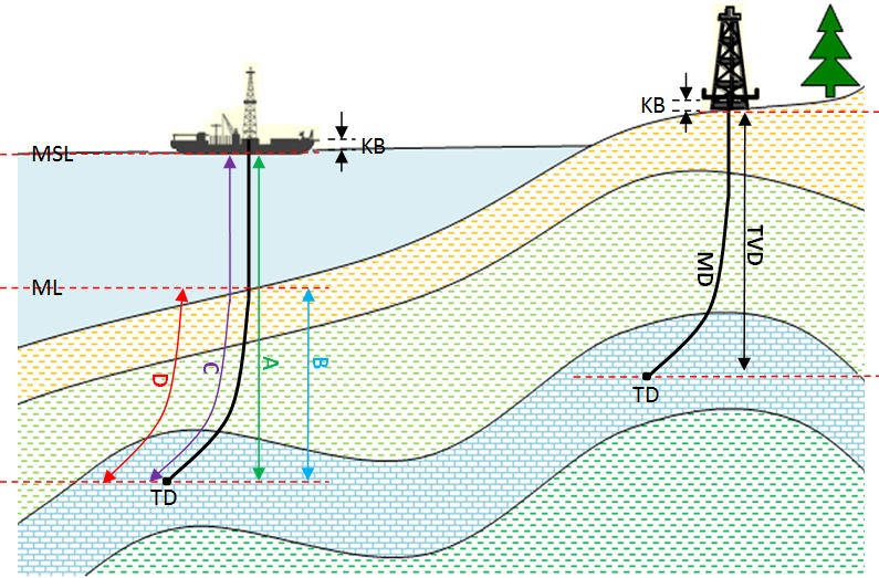
The kelly bushing is sometimes used as a reference point from which depth measurements can be taken. All depths must be recorded with respect to a reference point; the kelly bushing (KB) is one of the depth references used in the oil and gas industry.
The top of the kelly bushing is normally used as the depth reference.For example, 7500ft KB means 7500ft below the kelly bushing or 7500ft measured from the top of the kelly bushing down to that point in the well.
In some other cases, depths could be recorded as 7500ft MDBKB meaning 7500ft measured depth below the kelly bushing. This is mostly used when the measured depth is different from the true vertical depth of the well, common with deviated and horizontal wells.

In the oil and gas industry, depth in a well is the measurement, for any point in that well, of the distance between a reference point or elevation, and that point. It is the most common method of reference for locations in the well, and therefore, in oil industry speech, “depth” also refers to the location itself.
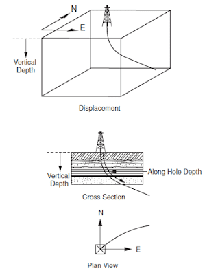
Because wells are not always drilled vertically, there may be two “depths” for every given point in a wellbore: the measured depth (MD) measured along the path of the borehole, and the true vertical depth (TVD), the absolute vertical distance between the datum and the point in the wellbore. In perfectly vertical wells, the TVD equals the MD; otherwise, the TVD is less than the MD measured from the same datum. Common datums used are ground level (GL), drilling rig floor (DF), rotary table (RT), kelly bushing (KB) and mean sea level (MSL). [1]
Kelly Bushing Height (KB):The height of the drilling floor above the ground level. Many wellbore depth measurements are taken from the Kelly Bushing. The Kelly bushing elevation is calculated by adding the ground level to the Kelly bushing height.
Driller’s Depth below rotary table (DDbrt): The depth of a well or features within the wellbore as measured while drilling. The measured length of each joint of drillpipe or tubing is added to provide a total depth or measurement to the point of interest. Drillers depth is the first depth measurement of a wellbore and is taken from the rotary table level on the rig floor. In most cases, subsequent depth measurements, such as those made during the well completion phase, are corrected to the wellhead datum that is based on drillers depth (reference: Schlumberger Oilfield Glossary).
Although depth calculation is an intuitive concept, it is the source of much confusion because it is frequently not specified correctly. Absolute depth should always be specified with three components:
True vertical depth is obtained from a record of the deviation survey report. These surveys are generally run on deviated wellbores. It records measured depth (MD), inclination (deviation angle), azimuth angle, true vertical depth, and dogleg severity at various increments. To obtain a TVD, simply obtain a measured depth, go to the survey, and read off the TVD. If the desired measured depth is not in the survey, then extrapolate between the two closest points.
In the oil and gas industry, depth in a well is the measurement, for any point in that well, of the distance between a reference point or elevation, and that point. It is the most common method of reference for locations in the well, and therefore, in oil industry speech, “depth” also refers to the location itself.
Because wells are not always drilled vertically, there may be two “depths” for every given point in a wellbore: the measured depth (MD) measured along the path of the borehole, and the true vertical depth (TVD), the absolute vertical distance between the datum and the point in the wellbore. In perfectly vertical wells, the TVD equals the MD; otherwise, the TVD is less than the MD measured from the same datum. Common datums used are ground level (GL), drilling rig floor (DF), rotary table (RT), kelly bushing (KB) and mean sea level (MSL). [1]
Kelly Bushing Height (KB):The height of the drilling floor above the ground level. Many wellbore depth measurements are taken from the Kelly Bushing. The Kelly bushing elevation is calculated by adding the ground level to the Kelly bushing height.
Driller’s Depth below rotary table (DDbrt): The depth of a well or features within the wellbore as measured while drilling. The measured length of each joint of drillpipe or tubing is added to provide a total depth or measurement to the point of interest. Drillers depth is the first depth measurement of a wellbore and is taken from the rotary table level on the rig floor. In most cases, subsequent depth measurements, such as those made during the well completion phase, are corrected to the wellhead datum that is based on drillers depth (reference: Schlumberger Oilfield Glossary).
Measured Depth (MD) is the distance measured along the actual course of the borehole from the surface reference point to the survey point. This depth is always measured in some way, for example, pipe tally, wireline depth counter, or mud loggers depth counter.
True Vertical Depth (TVD) is the vertical distance from the depth reference level to a point on the borehole course. This depth is always calculated from the deviation survey data.
In most drilling operations the rotary table elevation is used as the working depth reference. The abbreviation BRT (below rotary table) and RKB (rotary kelly bushing) are used to indicate depths measured from the rotary table. This can also be referred to as derrick floor elevation. For floating drilling rigs the rotary table elevation is not fixed and hence a mean rotary table elevation has to be used.
In order to compare individual wells within the same field, a common depth reference must be defined and referred to (e.g. When drilling a relief well into a blow-out well, the difference in elevation between the wellheads has to be accurately known). Offshore, mean sea level (MSL) is sometimes used. Variations in actual sea level from MSL can be read from tide tables or can be measured.

"I am very satisfied with both the service and professionalism that Total Depth Tools has provided. I have had a personal and business relationship with Jeremiah Belk for several years and will continue to use him for my drill pipe and miscellaneous equipment purchases in the future. Jeremiah is steadfast in his approach and always follows through with his promises. Total Depth Tools offers great communication, has a fast turnaround on quotes/orders, and provides excellent prices! Based on my experience, I am confident in my recommendation of Total Depth Tools and their products."

"I am very satisfied with both the service and professionalism that Total Depth Tools has provided. I have had a personal and business relationship with Jeremiah Belk for several years and will continue to use him for my drill pipe and miscellaneous equipment purchases in the future. Jeremiah is steadfast in his approach and always follows through with his promises. Total Depth Tools offers great communication, has a fast turnaround on quotes/orders, and provides excellent prices! Based on my experience, I am confident in my recommendation of Total Depth Tools and their products."
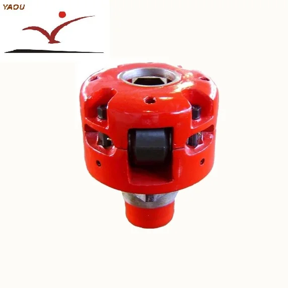
An adapter that serves to connect the rotary table to the kelly. The kelly bushing has an inside diameter profile that matches that of the kelly, usually square or hexagonal. It is connected to the rotary table by four large steel pins that fit into mating holes in the rotary table. The rotary motion from the rotary table is transmitted to the bushing through the pins, and then to the kelly itself through the square or hexagonal flat surfaces between the kelly and the kelly bushing. The kelly then turns the entire drillstring because it is screwed into the top of the drillstring itself. Depth measurements are commonly referenced to the KB, such as 8327 ft KB, meaning 8327 feet below the kelly bushing.
Well GY-668 has a planned total depth ("TD") of 3,000 feet measure depth ("MD") (equivalent to 2,880 feet true-vertical depth ("TVD")) to a bottom-hole location that is approximately 680 feet west of the surface location. The primary target of this well is the Gros Morne sandstones, the top of which are anticipated at a depth of approximately 2,150 feet TVD.

For drilling in the oil and gas industry and geothermal exploration and production, fracture pressure is the pressure required to fracture the formation and to cause mud losses from a wellbore into the induced fractures. Fracture gradient is obtained by dividing the true vertical depth into the fracture pressure. The fracture gradient is the upper bound of the mud weight; therefore, the fracture gradient is an important parameter for mud weight design in both stages of drilling planning and operations. If the downhole mud weight is higher than the formation fracture gradient, then the wellbore will have tensile failures (i.e., the formation will be fractured), causing losses of drilling mud or even lost circulation (total losses of the mud). Therefore, fracture gradient prediction is directly related to drilling safety.
Pore pressure gradient, fracture gradient, overburden stress gradient, downhole mud weight, and casing shoes versus depth. TVD presents the true vertical depth. Unit conversion: 1 ft = 0.3048 m, 1 ppg = 0.12 g/cm3
Fracture gradient is defined by the Schlumberger Oilfield Glossary as the pressure gradient required to induce fractures in the rock at a given depth. Based on this definition, the fracture gradient is the maximum mud weight that a well can hold without mud losses and without uncontrolled tensile failures (fracture growth). However, there is no consensus for a method to calculate the fracture gradient in the oil and gas industry. Some pore pressure specialists use the minimum stress gradient as the fracture gradient, but others may use the maximum leak-off pressure gradient (fracture breakdown pressure gradient) or the fracture initiation pressure gradient as the fracture gradient. In this paper, the maximum leak-off pressure gradient (the peak value in the LOT test) is used as the fracture gradient. That is, the effects of the minimum stress, tensile strength, and the wellbore stress concentrations will be considered for fracture gradient prediction.
Typically, a formation pressure integrity test or the formation leak-off test is performed in drilling operations to evaluate cement jobs, determine the casing setting depth, test the resistance of tensile failures of a casing shoe, and estimate formation fracture gradient (Postler 1997). Based on the injection pressure, volume, and time, pressure integrity tests can be classified into three, i.e., formation integrity test (FIT), leak-off test (LOT), and extended leak-off test (XLOT). The purpose of conducting a FIT is to test the formation fracture pressure required for kick tolerance and/or safe drilling mud weight margin. The maximum pressure in the FIT test is less than the fracture initiation and formation breakdown pressures.


 8613371530291