
kelly bushing elevation manufacturer
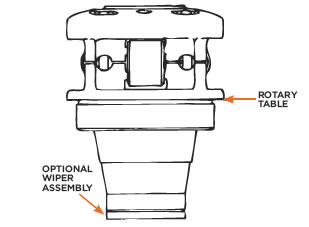
An adapter that serves to connect the rotary table to the kelly. The kelly bushing has an inside diameter profile that matches that of the kelly, usually square or hexagonal. It is connected to the rotary table by four large steel pins that fit into mating holes in the rotary table. The rotary motion from the rotary table is transmitted to the bushing through the pins, and then to the kelly itself through the square or hexagonal flat surfaces between the kelly and the kelly bushing. The kelly then turns the entire drillstring because it is screwed into the top of the drillstring itself. Depth measurements are commonly referenced to the KB, such as 8327 ft KB, meaning 8327 feet below the kelly bushing.
Kelly Bushing Height (KB): The height of the drilling floor above the ground level. Many wellbore depth measurements are taken from the Kelly Bushing. The Kelly bushing elevation is calculated by adding the ground level to the Kelly bushing height.
1. n. [Drilling] An adapter that serves to connect the rotary table to the kelly. The kelly bushing has an inside diameter profile that matches that of the kelly, usually square or hexagonal. It is connected to the rotary table by four large steel pins that fit into mating holes in the rotary table.
A Kelly bushing (some people call “rotary Kelly bushing”) engages a master bushing via four pins and rollers inside a Kelly bushing to allow a Kelly to move up or down freely while it is rotated or in a static mode. This video demonstrates how to make a connection via a Kelly system.
Kelly bushing is that elevated device positioned right on top of the rotary table and used to transmit torque from the rotary table to the kelly. The kelly bushing is designed to be the connection between the rotary table and the kelly.
1. n. [Drilling] An adapter that serves to connect the rotary table to the kelly. The kelly bushing has an inside diameter profile that matches that of the kelly, usually square or hexagonal. It is connected to the rotary table by four large steel pins that fit into mating holes in the rotary table.
The kelly is used to transmit rotary motion from the rotary table or kelly bushing to the drillstring, while allowing the drillstring to be lowered or raised during rotation.
1. adj. [Drilling] Referring to the condition that occurs when the kelly is all the way down, so drilling progress cannot continue. A connection must be made, which has the effect of raising the kelly up by the length of the new joint of drillpipe added, so drilling can resume.
This means that Top Drives can drill about 90 feet before making a connection, whereas with a Kelly System, you will make a connection at about 30 feet deep. Another difference between a Kelly and a Top Drive is that a Top Drive System allows rotation and circulation while back reaming out of a hole.
Kelly drive system is capable to drill with one single drill pipe. On other hand TDS is capable to drill with drill pipe stand. One drill pipe stand is made of three drill pipe joints together.
Kelly bars operate by transferring the torque and crowd force from a rotary drive tool to the drilling tool. Many kelly bars can be applied to any type of piling rig that is available on the market. Kelly bars can be divided into two main types: friction kelly bars and interlocking kelly bars.
The wear bushing is housed in the head or in the spool and is secured by means of two tie down screws to protect it against damage or wear during drilling. It is installed or retrieved with either a simple installation tool or with the HCC combined tool.
Kelly Saver Subs refer to a sub used between the Kelly or top head drive and the drill pipe. It is usually a pin to pin sub that takes the wear abuse to protect the drill pipe and the drive connection. Mills can furnish these subs along with the fluted, hex, or square Kelly Bar drive itself.
A mechanical device for rotating the kelly. The kelly spinner is typically pneumatic. It is a relatively low torque device, useful only for the initial makeup of threaded tool joints. It is not strong enough for proper torque of the tool joint or for rotating the drillstring itself.
This means that Top Drives can drill about 90 feet before making a connection, whereas with a Kelly System, you will make a connection at about 30 feet deep. Another difference between a Kelly and a Top Drive is that a Top Drive System allows rotation and circulation while back reaming out of a hole.
Kelly bars are key components in the execution of boreholes with hydraulic rotary drilling rigs. They transfer the torque of the rotary drive and the crowd pressure of the crowd system concurrently to the drilling tool.
A kelly drive is a type of well drilling device on an oil or gas drilling rig that employs a section of pipe with a polygonal (three-, four-, six-, or eight-sided) or splined outer surface, which passes through the matching polygonal or splined kelly (mating) bushing and rotary table.
A conventional rotary rig or rotary table rig or kelly drive rig is a drilling rig where the rotation of the drill string and bit is applied from a rotary table on the rig floor.
Kelly drive system is capable to drill with one single drill pipe. On other hand TDS is capable to drill with drill pipe stand. One drill pipe stand is made of three drill pipe joints together.
Kelly bars operate by transferring the torque and crowd force from a rotary drive tool to the drilling tool. Many kelly bars can be applied to any type of piling rig that is available on the market. Kelly bars can be divided into two main types: friction kelly bars and interlocking kelly bars.

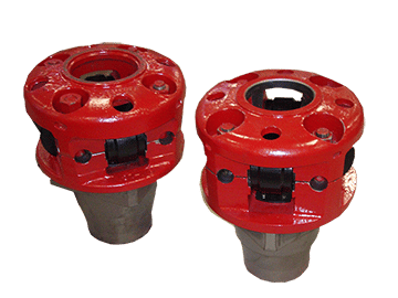
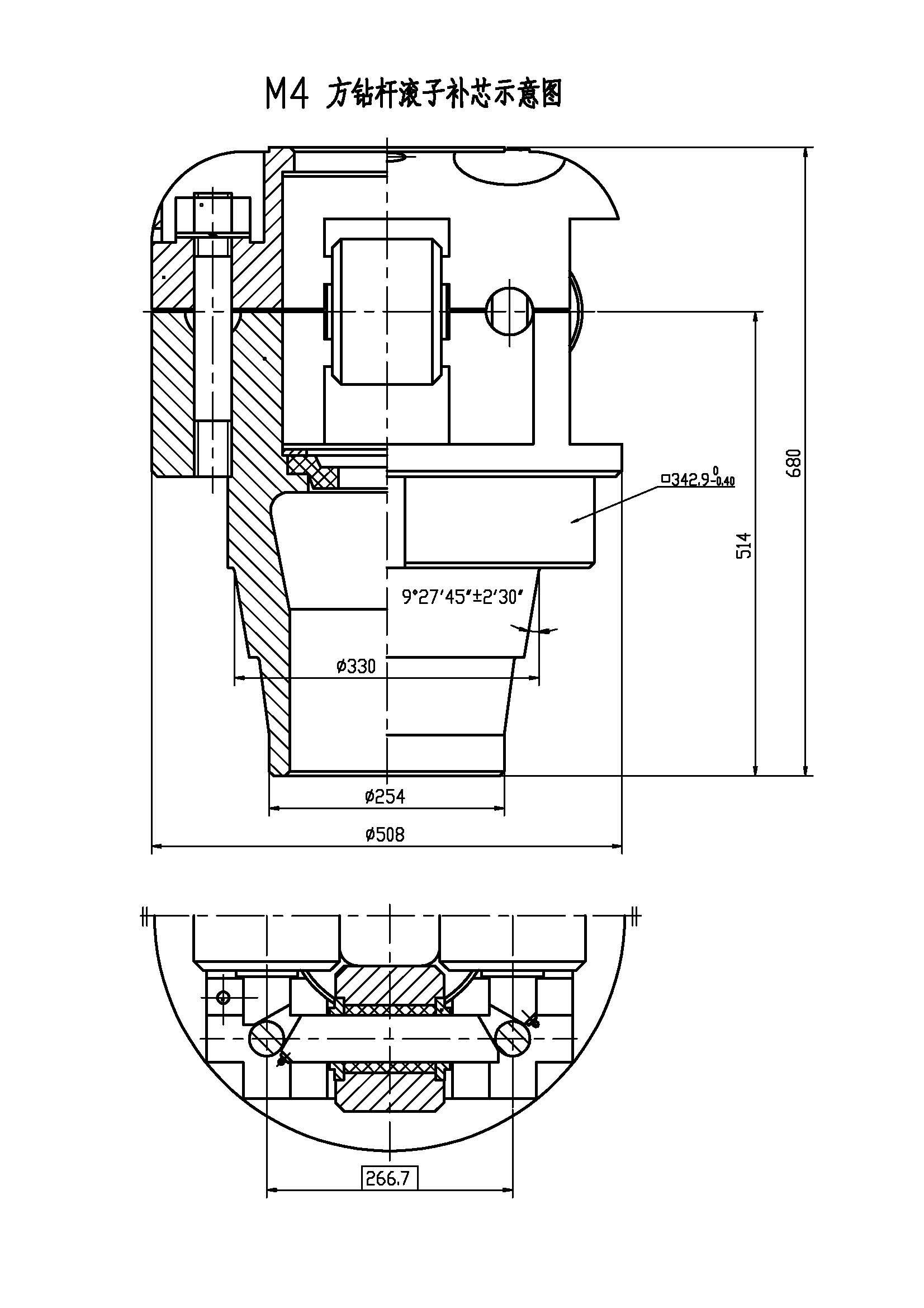
Roller Kelly Bushings are designed and manufactured as per API Spec 7K "Drilling and Well Servicing Equipment" for driving Kelly in the drilling operation.
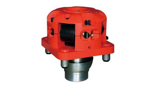
Roller kelly bushings are constructed in upper body half, low body half, rollers, rollers pin and etc., can be available in square drive or pin drive. Square drive roller kelly bushing designed with taper contact surface in low body half, while pin drive roller kelly bushing designed with pin to be installed in low body half.
According to torque of drilling, roller kelly bushing can be available in heavy duty, medium duty and light duty, heavy duty bushings are for high torque and high speed drilling operations while medium duty and light duty are for medium or shadow depth drilling operations.
Roller kelly bushings can accommodate square Kelly or hex Kelly, for square Kelly, the bushing is designed with four flat rollers, and for hex Kelly, the bushing is designed with two V-shaped rollers and two flat rollers. By changing roller size, roller kelly bushing can accommodate square Kelly from 2½" to 5¼" or hex Kelly from 3" to 6", and can be installed in rotary table range from 17½" to 37½".
At a previous employer a coworker came to me and told me that a group within our company had asked for all the KB (kelly bushing) elevations for every well in Colorado. I replied that it made no sense and asked my coworker to see if the reference elevations were what they really wanted. The coworker returned the next day and indicated that they had insisted on the KB elevations. We supplied the KB elevations and sure enough, about a week later they came back and asked for the reference elevations.
It’s really important to understand the data you’re working with – what it is, where it came from, and what it can be used for. The problem is sometimes actually harder than it seems. If we use the example above, most logs are measured from the KB elevation, correct? So you want KB elevations when normalizing logs to the sea-level datum?
Yes, most logs are measured from the KB. No, never use just the KB. Some logs are measured from the DF (derrick floor), GR (ground), or CHF (casing head flange), and there are a few other strange places logs are measured from. In today’s world, where multiple rigs can drill multiple sections of a well, the KB can have different elevations depending on the run of the log. It’s really important to put things back together on a common reference point so the logs aren’t off and formations can be correlated and depth corrected. (Side note: the definition of MSL, mean sea-level, is also probably a good topic of future discussion. It’s probably not what or where you think it is).
I really like to use the CHF as the reference elevation because after surface casing is run and cemented in, it is a constant point that has a single elevation point throughout the drilling and completion cycle. No matter what the elevation of the rig or completion is, the CHF is always at the same elevation.
So the KB is a physical place on the rig and the reference elevation is the physical place where the log was measured from. They can be the same thing but equating them everywhere will certainly create incorrect data.
Where the elevations come from is another question. Elevations are often supplied on the drilling permit, the completion report, the logs, and probably a couple of other reports.
The elevation starts when the surveyor goes out and measures precisely where the oil and gas company wants the well. Today everything is done by GPS, and the surveyor gets a latitude, longitude, and elevation. At the precise spot, the surveyor pounds a steak into the ground and ties an orange surveyor’s ribbon on it. It’s usually in some pasture and hopefully not on the side of a hill or in the middle of some pond. That does happen, however, despite the fact that the geologist spends months studying the subsurface. The thing is, they probably don’t spend more than 10 minutes looking at the surface.
Some companies will actually call back the surveyor to have him give a final elevation of the ground and of the KB and/or DF. If you’re really lucky, the company will have also asked the surveyor to respot the well location so there is an updated lat/long, but don’t count on it. One of the most shocking comments I’ve heard about well locations is, “I don’t worry about well locations anymore because everyone uses a GPS.” Yes, the surveyor used a GPS to place the stake in the ground … just before the bulldozer pushed it into the dirt pile.
If the ground elevation changed between the permit and the completion report, there’s an excellent chance the surveyor came back and resurveyed (and hopefully he also included an elevation to something permanent, like the CHF).
So the question is, now that we have established that we might have several different elevations, what is the best one to use? Oh how I wish that were the only question that needed answering. Elevations are reported to the state and elsewhere from lots of different sources. Permits, completions, activity reports, and logs are the main documents where this data can be found. Locations are a different story, and it is a rare event to see a correction.
The elevations off the log are probably the best to use. Though I have seen them wrong on the log, it’s a rare occurrence. The elevations are generally captured to support the geologist in making structure maps, so there’s a good chance they’ve been checked and verified.
The completion information is also another good place to grab the elevations. However, grabbing them from the permit would personally be my last choice, but it’s a lot better than nothing or an estimated elevation from a topo map or DLG file.
So the next time you are looking for an elevation, ask yourself, what was it referenced to, what document did it come from and, probably most importantly, is it a reasonable value?
A couple of other TDs come into play when you are drilling directional or horizontal wells. MTD is the measured total depth, which is the distance along the wellbore. The other piece of information is the true vertical depth (TVD), which is the distance of the well from the surface. There is actually one other measurement, called true vertical depth subsea (TVDSS), which is the TVD as referenced from the reference elevation. In many instances this ends up with data below the sea level and the values are negative. Think of this like a thermometer, where some values are below zero (below sea-level).

In the oil and gas industry, depth in a well is the measurement, for any point in that well, of the distance between a reference point or elevation, and that point. It is the most common method of reference for locations in the well, and therefore, in oil industry speech, "depth" also refers to the location itself.
By extension, depth can refer to locations below, or distances from, a reference point or elevation, even when there is no well. In that sense, depth is a concept related to elevation, albeit in the opposite direction. Depth in a well is not necessarily measured vertically or along a straight line.
Because wells are not always drilled vertically, there may be two "depths" for every given point in a wellbore: the borehole, and the datum and the point in the wellbore. In perfectly vertical wells, the TVD equals the MD; otherwise, the TVD is less than the MD measured from the same datum. Common datums used are ground level (GL), drilling rig floor (DF), Rotary table (RT), kelly bushing (KB or RKB) and mean sea level (MSL).
Sign Convention - Depth increases positive in the downward direction. This may seem intuitive but confusion can arise when using certain references while integrating data from different sources. Workers mapping surfaces typically use elevation which, by convention, increases positive in the upward direction. Be mindful when integrating depth and elevation. For example, shallow wells drilled onshore often encounter reservoir at negative depths when referenced to sea level, mappers would define these same reservoirs at positive elevations when referenced to sea level.
The acronym TVDSS is commonly used in the oil industry to represent TVD minus the elevation above mean sea level of the depth reference point of the well. The depth reference point is the kelly bushing in the United States and a few other nations, but is the drill floor in most places.
Common references used in operations include: Rotary Table (RT), Drill Floor (DF), Kelly Bushing (KB), Sea Bottom (SB), Ground Level (GL), Casing Bowl Flange (CBF).

In the oil and gas industry, depth in a well is the measurement, for any point in that well, of the distance between a reference point or elevation, and that point. It is the most common method of reference for locations in the well, and therefore, in oil industry speech, “depth” also refers to the location itself.
Because wells are not always drilled vertically, there may be two “depths” for every given point in a wellbore: the measured depth (MD) measured along the path of the borehole, and the true vertical depth (TVD), the absolute vertical distance between the datum and the point in the wellbore. In perfectly vertical wells, the TVD equals the MD; otherwise, the TVD is less than the MD measured from the same datum. Common datums used are ground level (GL), drilling rig floor (DF), rotary table (RT), kelly bushing (KB) and mean sea level (MSL). [1]
Kelly Bushing Height (KB):The height of the drilling floor above the ground level. Many wellbore depth measurements are taken from the Kelly Bushing. The Kelly bushing elevation is calculated by adding the ground level to the Kelly bushing height.
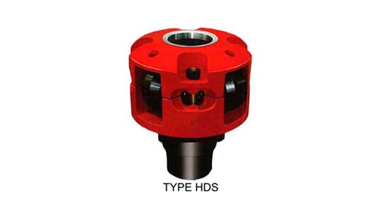
The JOTKB MODEL 27 PDHD OR 20 PDHD are developed for pin drive master bushing for rotary table sizes from 27-1/2" to 49-1/2" having 25-3/4" and 23" dia pin center. This unit is used for heavy duty drilling operations and high torque conditions on off shore as well as on shore drilling operations, and handle Kelly sizes from 3" to 6" Square or Hexagonal.
This invention pertains to kelly drives used in the rotary method of drilling. More particularly the invention pertains to roller kelly drive bushings adapted to fit in the master bushing of a rotary table such as used in drilling for oil by the rotary method.
Briefly the invention includes a body having a circular base beneath which extends a square pin adapted to be received in the square socket of a rotary table master bushing and above which extend four pairs of posts providing four sets of shaft support holes. The posts of each pair are asymmetrically placed relative to the base diameters. Between each pair of posts is pivotally mounted an H shaped cage with a shaft extending through the cross bar of the H shaped cage into the pair of support holes provided by the posts, the cage cross bar having a bushing where it pivots about the shaft. Each cage carries a pair of rollers rotatably mounted on shafts carried by the opposite ends of the cage, the rollers being provided with bushings to rotate on the shafts. Releasable means is provided to fix each cage and roller shaft against rotation and prevent axial motion thereof. Each cage and roller shaft has an axial grease passage therethrough joining radial passages communicating with the exterior of the shaft within the corresponding bushing. Each bushing is recessed adjacent the ends of the radial passages in the shaft to communicate the grease with the whole periphery of the shaft. Spring pressed ball check valves in the ends of the axial passages through the shafts provide means for introducing grease. Different sizes and shapes of rollers can be used. A lower cylindrical housing is secured to the body on top of the base; an upper housing is releasably connected to the tops of the posts. Ports in the housings permit access to the grease valves for lubricating the shafts and bushings.
The centrally pivoted cage mounted rollers cause the kelly to be driven smoothly without wobbling, whip, vibration, or binding during axial feed, despite misalignment of the rotary table and crown block and despite crookedness of the kelly, while assuring positive drive and adequate dispersal of driving pressure on the kelly. This arises by virtue of the kinematic geometry of the pivot cage mounted rollers whereby the normal tolerances needed to fit any bushing around a kelly allow the caged rollers to align themselves with the kelly despite such misalignment and crookedness. The resulting absence of bending moments in the kelly reduces wear and vibration and prevents binding. The kinematics of the caged rollers makes it impossible for but one of the rollers of each cage to take all of the driving torque, thereby insuring adequate dispersal of driving pressure and avoiding Brinnelling of the kelly.
The ready removal and replacement of the roller cage shafts makes it a simple matter to remove two adjacent cages so that the apparatus can be threaded over the enlarged end of a kelly and the cages replaced prior to use.
The adaptability of the apparatus to use with standard A.P.I. master bushings and the easy removal and replacement of the roller shafts whereby change of rollers to fit difierent sizes and shapes of kellys is facilitated makes the apparatus of wide applicability.
FIGURE 1 is a front elevation of a kelly bushing embodying the invention having rollers therein adapted to engage a square kelly of medium size, the housings being cut away in vertical section to show the interior of the apparatus, and portions of the front cage and lower roller being sectioned to show the lubrication systems therefor;
FIGURE 2 is a plan View of the FIGURE 1 apparatus with both of the housings broken away and one cage broken away partially to show the lower roller, different rollers having been substituted suitable for use with a large size hexagonal kelly;
FIGURE 3 is a perspective of the apparatus of FIG- URE 2 showing the exterior thereof, the apparatus being shown disposed in a rotary table and around a hexagonal kelly, and illustrating the manner of servicing the bearings.
Referring now to FIGURES l and 2, the twoapparatuses being identical except for the rollers, there is shown a body 10 having a circular base portion 11. Beneath the base extends a square pin 12 adapted to fit in the master bushing of a conventional rotary table. The upper portion 13 of the base 11 is of reduced diameter providing a shoulder 14 on which rests a cylindrical lower husing :15. The lower housing is welded to the base at 16.
There is a circular cross section passage 20 through the body adapted to receive a kelly such as hexagonal kelly 21, shown only in FIGURE 2 (and FIGURE 3). There is a counterbore 22 in the lower end of pin 12 adapted to rest on the pin of a support in the rat hole (not shown) when the kelly and kelly bushing are not in use: Preferably passage 20 is slightly flaring downwardly, as shown in FIGURE 1, to facilitate placement thereof over the upper end of a kelly.
Each plate is provided with a hole 50 beneath which is disposed a threaded nut 51 welded to the plate concentrio with the hole. The peripheries of plates 39-42 are of less radial extent than the outer edges of the posts leaving shoulders such as 56., 57 to facilitate placement of an per housing 58. Housing 58 is dome shaped and has an opening 59 through the top thereof through which a kelly may pass. There are four indented portions such as 60, 61 around the upper housing, the lower portions of which are fiat and adapted to rest on top of the plates. There is a hole through each indented portion of the upper housing adapted to receive a screw such as 62, 63 which engages the nuts beneath the plates to hold the housing in position.
Each shaft 72 has a cage 80 pivotally mounted thereon. Each cage is of H shape with a hole 81 through the cross bar receiving the corresponding shaft 72. The holes 81 are provided with bronze bushing sleeves 82. Within each sleeve 82 is an annular grease reservoir groove 83. Communicating with groove 83 are radial passages 84, 85 in the shaft 72 which connect to axial passage 86 extending from one end of shaft 72 to the other. The ends of passage 86 are counterbored and threaded as shown at 87, 88 to receive check valve fittings 89 adapted to be connected to a conventional grease gun. Referring momentarily to FIGURE 3, four openings 90 spaced around the lower housing 15 provide access to the grease check valve fittings without the necessity of removing the housings.
Returning to FIGURES 1 and 2, when grease is pumped through a check valve 89 it goes through an axial passage 86 and out through radial passages 84, 85 into annular reservoir 83 and thence out between the bushing sleeve 82 and shaft 72, flushing out the old grease ahead of it. The grease escaping at the ends of shaft "72 goes into the space between bosses 90, 91 on the cage and bosses 92, 93 on the posts forming a seal against entrance of dirt, water and other foreign matter to the bearing area between sleeve82 and shaft 72.
Between the pairs of legs 101-102, 101"-102 at the"upper and lower ends of each H-shaped cage 80 are rotatably mounted rollers such as rollers 103, 104, 105", 106" shown in FIGURE 1. The rollers are mounted on shafts such as 107 on which rollers 104 is mounted. Each roller has a bushing sleeve such as 108 in roller 104. Shaft 107 is prevented from turning and moving axially by washers such as 109, 110, similar to the mounting of shaft 72. Shafts 107 and bushing sleeves 108 are provided with axial, radial, and annular grease passages 111, 112, 113 similar to those of shaft 72 and sleeve 82, to which grease is pumped through check valves 114, 115, screwed into counterbores 116, 117 in the ends of the shaft 107. When it is desired to lubricate the rollers, a conventional grease gun is used the same as for the cage.
When the grease in the roller lubrication passages is flushed out, the excess grease exuding between the ends of bushing sleeves 108 and shafts 107 escapes into the space between bosses 140, 141 on the inside of the cage and the adjacent sides of the rollers to form seals against dirt, water and other foreign matter.
Referring particularly to FIGURE 2, there are shown the rollers used to drive a hexagonal kelly. In the cages 80, on the front and back sides of the apparatus there are cylindrical rollers such as 151, 152 in the tops of the cages and like rollers in the bottoms of the cages. In the cages 153, 154 at the sides of the apparatus are disposed pairs of rollers such as upper roller 155 and lower roller 156. Top roller 155 in cage 153 is conical and adapted to engage a side of the kelly adjacent the side engaged by roller 151. The roller in the bottom of cage 153 is similar to roller 156 and is adapted to engage the side of the kelly adjacent to the side engaged by roller 152. Similarly the upper and lower rollers of cage 154 are adapted to engage different sides of the kelly.
It will be noted that the pairs of posts supporting each roller are asymmetrically located with respect to the diameters through the center of the kelly perpendicular to the roller axes, being displaced clockwise, so that when larger diameter rollers are used to drive smaller size kellys, the rollers do not interfere, while at the same time each roller bears at or near the leading corner of the adjacent side of the kelly where it has the maximum torque radius. The posts provide means holding each cage against all rotation about a vertical axis relative to the body 10.
It is because of the asymmetric positioning of the pairs of posts that the two rollers for the side cages are of different shape to engage the two different sides of the kelly. The roller 156, engaging the side of the kelly, has its largest cone diameter at the end of the roller nearest the perpendicular diameter (the diameter through the kelly center and perpendicular to the roller axis). Therefore the largest cone diameter of roller 156 is smaller than that of roller 155 whose largest cone diameter is at the end of the roller farthest from the perpendicular diameter. Because the largest diameter of roller 156 is smaller, it is necessary to discontinue the cone taper after it leaves the kelly and finish off with a cylindrical portion 181. The juncture between the conical and cylindrical portions is provided with a stress relief groove 182.
When larger diameter rollers are substituted to engage a smaller kelly, the cylindrical rollers are bevelled on their ends that are farthest from the perpendicular diameter. This is shown at 191, 192, 193 in FIGURE 1. This provides additional clearance without reducing the area of contact with the kelly which in such case has smaller sides available for contact by the rollers.
In operation of the kelly bushing above described, it is to be noted that if a cage tilts so that one of its rollers is out of contact with the kelly or has less contact pressure than the other, there is created a torque automatically turning the cage about its axis to equalize the pressures of the upper and lower rollers. The same torque also automatically places each cage parallel to the kelly axis instead of placing a bending moment on the kelly to align it with the cage. These are marked advantages over roller kelly bushings having the rollers mounted on fixed axes.
In connection with the alignment of the cages with the kelly, it is to be noted that when the cages turn out of their vertical positions in order to follow a crooked or non-vertical kelly, the distance between the cages is reduced slightly. However with the usual tolerances required to manufacture and assemble the apparatus and to place it over a kelly, the distance between the cages and their rollers is not reduced to a point sufficient to bind on the kelly until the cage has moved far more than the maximum amount needed to accommodate any deviation of the kelly from vertical that is to be expected in practice. The elasticity of the materials increases the amount of angular displacement of the cages possible without binding on the kelly.
1. A roller kelly bushing comprising a body having a vertical hole therethrough to receive a kelly, a plurality of pairs of cages, the cages of each pair being disposed on diametrically opposite sides of said hole, means independently pivotally mounting each cage directly on the body for rotation about a horizontal axis perpendicular to a radius from said hole extending through the cage and simultaneously holding the cage against all rotation about a vertical axis relative to said body, each cage having a roller rotatably mounted thereon above the cage pivot axis and another roller rotatably mounted thereon below the cage pivot axis, the position of each of said pairs of cages being unaffected by the rotation of the other of said pairs of cages.
3. A roller kelly bushing comprising a body including a base having a vertical hole therethrough to receive a kelly and four pairs of vertical posts on the upper side of of the base, four shafts disposed with one between each pair of posts with its axis horizontal, said pairs of posts being placed so as to locate said four shafts with the axis of each lying along a different one of the four sides of a rectangle extending around said hole, fou-r cages each independently pivotally mounted on one of said shafts for rotation about the axis thereof, the location of said shafts disposing said cages in two pairs with the cages in each pair on opposite sides of said hole, each cage having a roller rotatably mounted thereon above the cage pivot axis and another roller rotatably mounted thereon below the cage pivot axis, the rollers of one cage of one pair of cages being adapted to engage one side of a kelly and the rollers of the other cage of said one pair being adapted to engage the opposite side of the kelly and said cages of said one pair rotating equal amounts about their shafts in case of misalignment of the kelly, the position of the other of said pairs of cages being unaffected by the rotation about its shafts of said one of said pairs of cages, said posts holding said cages against all rotation about a vertical axis relative to said body and against all rotation about a horizontal axis other than the axis of said shaft.
4. A roller kelly bushing comprising a body including a base having a vertical hole therethrough to receive a kelly and a plurality of pairs of vertical posts on the upper side of the base, a shaft disposed between each pair of posts with its axis horizontal and perpendicular to a radius from the hole, a plurality of cages each pivotally mounted on one of said shafts for rotation about the axis thereof, each cage being of H shape with the bar of the H forming the pivot axis of the cage, eagh cage having a roller rotatably mounted thereon between the upper legs of the H and another roller rotatably mounted thereon between the lower legs of the H.
5. A roller kelly bushing comprising a base having a hole vertically therethrough to receive a kelly and a plurality of cages each pivotally mounted thereon for rotation about a horizontal axis, each cage having a roller rotatably mounted thereon above the cage pivot axis and another roller rotatably mounted thereon below the cage pivot axis, characterized by the fact that there are four pairs of posts, four cages, one cage being mounted between each of the four pairs of posts, the pairs of posts are equally spaced around the top of the base, the rollers on two opposite cages all have cylindrical portions for contacting a kelly, and the other two cages have conical rollers for contacting a kelly, the upper and lower conical rollers in each of the last two said cages tapering in opposite directions.

Kelly bushing is that elevated device positioned right on top of the rotary table and used to transmit torque from the rotary table to the kelly. The kelly bushing is designed to be the connection between the rotary table and the kelly. The kelly is a 4 or 6 sided steel pipe.
The purpose of the rotary table is to generate the rotary action (torque) and power necessary to rotate the drillstring and drill a well. The torque generated by the rotary table is useless if it is not transferred to the kelly (the drillstring is connected to the kelly).
Hence, through the kelly bushing the torque generated at the rotary table is transferred to the kelly. To achieve this connection, the inside profile of the kelly bushing matches the outer profile of the kelly so that the kelly fits or “sits” comfortably in the kelly bushing.
There are various designs for the kelly bushing including the split type, the pin-drive type and the square-drive type. Each of these designs has different ways in which they are connected and disconnected from the rotary table.
The internal diameter of the kelly bushing can be cut into the shape of a square (4-sided) or a hexagon (6-sided) depending on the outer shape of the kelly that will be used. The internals of a Kelly bushing is designed to resemble the outer shape of a Kelly just like the insides of a key lock is cut to exactly match the outer shape of the key.
The kelly bushing is not designed to hold tightly onto the Kelly; the kelly is still permitted to move up and down through the kelly bushing. This requirement is a must since drilling cannot progress if the kelly remains on a fixed spot. As the well is drilled deeper, the kelly also moves downward through the Kelly bushing.
The kelly bushing is sometimes used as a reference point from which depth measurements can be taken. All depths must be recorded with respect to a reference point; the kelly bushing (KB) is one of the depth references used in the oil and gas industry.
The top of the kelly bushing is normally used as the depth reference.For example, 7500ft KB means 7500ft below the kelly bushing or 7500ft measured from the top of the kelly bushing down to that point in the well.
In some other cases, depths could be recorded as 7500ft MDBKB meaning 7500ft measured depth below the kelly bushing. This is mostly used when the measured depth is different from the true vertical depth of the well, common with deviated and horizontal wells.


 8613371530291