
kelly bushing elevation correction manufacturer

In the oil and gas industry, depth in a well is the measurement, for any point in that well, of the distance between a reference point or elevation, and that point. It is the most common method of reference for locations in the well, and therefore, in oil industry speech, "depth" also refers to the location itself.
By extension, depth can refer to locations below, or distances from, a reference point or elevation, even when there is no well. In that sense, depth is a concept related to elevation, albeit in the opposite direction. Depth in a well is not necessarily measured vertically or along a straight line.
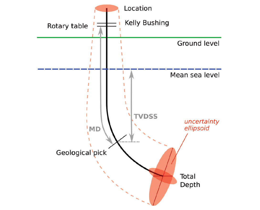
Because wells are not always drilled vertically, there may be two "depths" for every given point in a wellbore: the borehole, and the datum and the point in the wellbore. In perfectly vertical wells, the TVD equals the MD; otherwise, the TVD is less than the MD measured from the same datum. Common datums used are ground level (GL), drilling rig floor (DF), Rotary table (RT), kelly bushing (KB or RKB) and mean sea level (MSL).
Example: the top of a reservoir may be found at 1,500 mMDRT in a particular well (1,500 m measured depth below the rotary table), which may be equal to 1,492 mTVDMSL (1,492 m true-vertical-depth below mean sea level) after correction for deviations from vertical.
Sign Convention - Depth increases positive in the downward direction. This may seem intuitive but confusion can arise when using certain references while integrating data from different sources. Workers mapping surfaces typically use elevation which, by convention, increases positive in the upward direction. Be mindful when integrating depth and elevation. For example, shallow wells drilled onshore often encounter reservoir at negative depths when referenced to sea level, mappers would define these same reservoirs at positive elevations when referenced to sea level.
The acronym TVDSS is commonly used in the oil industry to represent TVD minus the elevation above mean sea level of the depth reference point of the well. The depth reference point is the kelly bushing in the United States and a few other nations, but is the drill floor in most places.
The distinction between "loggers" depth" and "drillers" depth" is becoming blurred due to the increasing use of logs acquired while drilling (LWD). At the time of writing, the common practice remains that the petrophysicists or geologists define the "official depths" in a well, and these depths are frequently different from the "drillers" depth", after various corrections, tie-ins, etc., have been applied.
the legal datum offshore Australia is Lowest Astronomical Tide (LAT) – (Ref. 1 & 2). Note that this requirement in itself can cause difficulties as it is difficult to measure offshore and can vary greatly between locations and even with time. There is, however, an advantage to this convention: tidal corrections should always be of the same sign (negative depth), i.e. the sea level is always higher than or equal to LAT.
Common references used in operations include: Rotary Table (RT), Drill Floor (DF), Kelly Bushing (KB), Sea Bottom (SB), Ground Level (GL), Casing Bowl Flange (CBF).
At a previous employer a coworker came to me and told me that a group within our company had asked for all the KB (kelly bushing) elevations for every well in Colorado. I replied that it made no sense and asked my coworker to see if the reference elevations were what they really wanted. The coworker returned the next day and indicated that they had insisted on the KB elevations. We supplied the KB elevations and sure enough, about a week later they came back and asked for the reference elevations.
It’s really important to understand the data you’re working with – what it is, where it came from, and what it can be used for. The problem is sometimes actually harder than it seems. If we use the example above, most logs are measured from the KB elevation, correct? So you want KB elevations when normalizing logs to the sea-level datum?
Yes, most logs are measured from the KB. No, never use just the KB. Some logs are measured from the DF (derrick floor), GR (ground), or CHF (casing head flange), and there are a few other strange places logs are measured from. In today’s world, where multiple rigs can drill multiple sections of a well, the KB can have different elevations depending on the run of the log. It’s really important to put things back together on a common reference point so the logs aren’t off and formations can be correlated and depth corrected. (Side note: the definition of MSL, mean sea-level, is also probably a good topic of future discussion. It’s probably not what or where you think it is).
I really like to use the CHF as the reference elevation because after surface casing is run and cemented in, it is a constant point that has a single elevation point throughout the drilling and completion cycle. No matter what the elevation of the rig or completion is, the CHF is always at the same elevation.
So the KB is a physical place on the rig and the reference elevation is the physical place where the log was measured from. They can be the same thing but equating them everywhere will certainly create incorrect data.
Where the elevations come from is another question. Elevations are often supplied on the drilling permit, the completion report, the logs, and probably a couple of other reports.
The elevation starts when the surveyor goes out and measures precisely where the oil and gas company wants the well. Today everything is done by GPS, and the surveyor gets a latitude, longitude, and elevation. At the precise spot, the surveyor pounds a steak into the ground and ties an orange surveyor’s ribbon on it. It’s usually in some pasture and hopefully not on the side of a hill or in the middle of some pond. That does happen, however, despite the fact that the geologist spends months studying the subsurface. The thing is, they probably don’t spend more than 10 minutes looking at the surface.
Some companies will actually call back the surveyor to have him give a final elevation of the ground and of the KB and/or DF. If you’re really lucky, the company will have also asked the surveyor to respot the well location so there is an updated lat/long, but don’t count on it. One of the most shocking comments I’ve heard about well locations is, “I don’t worry about well locations anymore because everyone uses a GPS.” Yes, the surveyor used a GPS to place the stake in the ground … just before the bulldozer pushed it into the dirt pile.
If the ground elevation changed between the permit and the completion report, there’s an excellent chance the surveyor came back and resurveyed (and hopefully he also included an elevation to something permanent, like the CHF).
So the question is, now that we have established that we might have several different elevations, what is the best one to use? Oh how I wish that were the only question that needed answering. Elevations are reported to the state and elsewhere from lots of different sources. Permits, completions, activity reports, and logs are the main documents where this data can be found. Locations are a different story, and it is a rare event to see a correction.
The elevations off the log are probably the best to use. Though I have seen them wrong on the log, it’s a rare occurrence. The elevations are generally captured to support the geologist in making structure maps, so there’s a good chance they’ve been checked and verified.
The completion information is also another good place to grab the elevations. However, grabbing them from the permit would personally be my last choice, but it’s a lot better than nothing or an estimated elevation from a topo map or DLG file.
So the next time you are looking for an elevation, ask yourself, what was it referenced to, what document did it come from and, probably most importantly, is it a reasonable value?
A couple of other TDs come into play when you are drilling directional or horizontal wells. MTD is the measured total depth, which is the distance along the wellbore. The other piece of information is the true vertical depth (TVD), which is the distance of the well from the surface. There is actually one other measurement, called true vertical depth subsea (TVDSS), which is the TVD as referenced from the reference elevation. In many instances this ends up with data below the sea level and the values are negative. Think of this like a thermometer, where some values are below zero (below sea-level).
In the rotary method of deep well drilling a rotary table is provided at the derrick to drive or rotate the drilling string. A drill stem or kelly of polygonal cross section is provided on the upper end of the drilling string and operates in what is known as a Kelly bushing in the rotary table. The engagement of the Kelly bushing with the kelly is such that rotation is transmitted from the rotary table to the kelly and the kelly is capable of vertical movement through the bushing while the rotation transmitting engagement is maintained. The kelly and the Kelly engaging parts of the bushing are subjected to severe wear and as a result slap and play soon develop between the bushing and the kelly. If this condition is not corrected the drive stem or kelly may be irreparably damaged.
Another object of the invention is to provide a Kelly bushing embodying novel means for adjusting its Kelly engaging parts to maintain them in correct engagement with the drill stem or kelly.
Another object of this invention is to provide a Kelly bushing embodying simple, practical and easily operated means for adjusting the several stem or Kelly engaging parts to preserve the corSrect engagement thereof with the kelly.
Another object of this invention is to provide a Kelly bushing embodying groups or series of rotatable rollers, each series operating to engage a face of the polygonal kelly and separate means for adjusting the series of rollers to maintain a uniform engagement of the rollers with the faces of the kelly and to assure a well distributed transmission of forces, thereby greatly reducing wear and the accompanying play and looseness.
Another object of this invention is to provide a Kelly bushing of the character mentioned in which separate carriers or cages are provided to support one or more series of rollers and each cage is independently adjustable by simple manipulation of a screw to bring its rollers into proper contact with the kelly.
Another object of this invention is to provide a Kelly bushing of the character mentioned in which each cage and its respective rollers and adjusting means form a unit that may be conveniently handled, serviced, etc.
Another object of this invention is to provide 65 a Kelly bushing of the character mentioned in which the adjusting means are positive and serve to maintain their respective cages and rollers in given or set positions until the adjustments are subsequently changed.
A further object of this invention is to provide an adjustable Kelly bushing in which the Kelly engaging parts may be adjusted quickly and with a minimum of labor.
The various objects and features of our invention will be fully understood from the following detailed description of a typical preferred form and application of the invention, throughout which description reference is made to the accompanying drawings, in which: Pig. 1 is a side elevation of the improved Kelly bushing provided by this invention engaged about a kelly and seated in a rotary table, illustrating the rotary table in a central vertical section. Fig. 2 is an enlarged fragmentary plan view taken as indicated by line 2-2 on Fig. 1 showing the kelly in cross section. Fig. 3 is a vertcal detailed sectional view of the Kelly bushing taken as indicated by line 3-3 on Fig. 2.
Fig. 4 is a horizontal detailed sectional view taken substantially as indicated by line 4-4 on Fig. 3. Fig. 5 is a rear elevation of one of the cages and its adjusting element removed from the body and Fig. 6 is a top or plan view of the assembly shown in Fig. 5.
The bushing of the present invention is intended primarily for use in the rotary table of a well drilling apparatus to drive or rotate the drilling . string. In the following detailed description we will describe the bushing of the invention employed in a typical rotary table to engage or drive a drill stem or kelly of octagonal transverse cross section. It is to be understood that modifications or changes may be made in the bushing of the invention to adapt it for use with other forms of well drilling equipment and that the particular application of the invention illustrated is not to be construed as limiting or restricting the use or scope of the invention.
The typical rotary unit illustrated in Figs. 1 and 2 of the drawings includes a rotary table T rotatably supported on a race or support 10 through a suitable bearing I. A driven pinion 12 meshes with ring gear teeth 13 on the under side of the table T to rotate the table. The table T-is provided with a central vertical opening 14 and a master bushing Bis fitted in the opening 14 to rotate with the table T. The master bushing B has a central vertical opening 15 whose upper portion is polygonal or square in transverse cross section. The portion of the opening 15 immediately below its polygonal part is conical or tapered. The improved bushing of the invention is adapted to be seated in the opening I5 to engage or drive a kelly K. The stem or kelly K illustrated is an elongate member of octagonal transverse cross section having eight flat vertical faces F. The kelly K extends centrally and vertically through the table and bushing asembly and may be considered as connected with the well drilling string.
The improved Kelly bushing of the invention may be said to comprise, generally, a body 16 to be seated in the opening 15, a plurality of cages 17 in the body 16 for engaging the kelly K and means 19 associated with the cages 17 for adjusting them with respect to the kelly K to obtain the correct engagement of the rollers 18 with the kelly.
The bushing body 16 is a tubular structure or member for carrying the cages 17 and the other parts of the bushing. The body 16 is shaped to seat in the opening 15 of the master bushing B. The lower part 20 of the body 16 is round in horizontal cross section and is tapered to fit in the tapered portion of the opening 15.
The adjacent portion of the body 16 is polygonal or square in external configuration to fit the square portion of the opening 15 whereby the Kelly .bushing rotates with the table T. The upper portion 21 of the body 16 is round or cylindrical in external configuration for the purpose to be hereinafter described. Four equally spaced laterally projecting lugs 22 are provided on the exterior of the body 16 immediately below its cylindrical upper portion 21.
The cages 17 form supports or carriers for the rollers 18 and are arranged in the tubular body 16 to have their rollers contact the faces F of the kelly K. The cages 17 may be identical and may be integral one-piece members. In the construction illustrated the cages 17 are frame-like members having flat parallel upper and lower ends 26 and 27, respectively, and flat parallel opposite sides 28. The lower ends 27 of the cages 17 are adapted to rest on the flange 25 and the upper ends 26 of the cages lie in a plane slightly above the upper end of the bushing body 16. The outer faces of the cages 17 with respect to the central axis of the bushing are of special formation, as will be subsequently described. The inner side of each cage 17 nas two angularly related or convergent vertical faces 29. Vertical openings or slots 30 are provided in the cages 17 to hold or receive the rollers 18. In the form of the invention illustrated there are two slots 30 in each cage 17. The slots 30 have their ends spaced from the upper and lower ends 26 and 27 of the cages 17 and extend horizontally through the cages from between their inner and outer sides. The side walls of the slots 30 are preferably flat and substantially parallel and in the construction illustrated extend outwardly at right angles to the adjacent inner faces 29 of the cages 1T.
The inner corners of the cages 17 have angular parts 31 and the parts 31 of the adjacent cages 17 are in nesting or meshing relation as clearly illustrated in Figs. 2 and 4 of the, drawings. It is preferred that the parts 31 of the adjacent cages 17 have substantial clearance whereby the cages may be independently adjusted toward and away from the central vertical axis of the bushing. The rollers 18 are the kelly engaging parts of the bushing. The rollers 18 may be identical and are cylindrical tubular parts with flat parallel ends. In accordance with the invention there is a plurality or series of vertically spaced rollers 18 in each slot 30. The rollers 18 are supported in the slots 30 to rotate about substantially horizontal axes. The means for supporting the rollers .18 include shafts or pins 32 arranged in openings 33 in the cages 171., The openings 33 intersect the slots 30 and the pins 32 extend .through the tubular rollers 18 and have their opposite end portions supported in the openings 33. The rollers 18 are freely rotatable on their respective pins 32. The pins 32 may be secured in their openings 33 in any suitable manner, for example they may be pressed or force-fitted in the openings. The rollers 18 of a set or series are vertically spaced apart to be independently rotatable. The ends of the rollers 18 have suitable working clearance with the flat vertical side walls of the slots 30.
In accordance with the invention the rollers 18 project slightly from the inner angular faces 29 of the cages 17 to cooperate with the kelly K. There is a series of rollers 18 for engaging each flat face P of the polygonal kelly K. This assures an effective distribution of turing forces throughout the circumference of the kelly. The rollers 18 are preferably of substantial length 4 to have extensive engagement with the faces F of the kelly K.
It is preferred to provide means for lubricating the rotatable rollers 18 so that the engagement of the rollers with the kelly offers a mini- 4& mum of resistance to vertical movement of the kelly K through the bushing. The inner ends of the aligned pin supporting openings 33 are in communication. Vertical lubricant ports 35 extend into the cages 17 from their upper ends and intersect the communicating inner end parts of the openings 33 to deliver lubricant to the openings. Longitudinal lubricant ports 36 enter the pin 32 from their inner ends and conduct the lubricant from the openings 33 to lateral ports 37. The lateral ports 37 in the pins 32 discharge the lubricant into the openings of the tubular rollers 18 to lubricate the rollers. Suitable grease gun fittings 38 are provided at the upper ends of the ports 35 to facilitate the introduction of lubricant under pressure to the lubricant port systems. The grease gun fittings 38 are preferably recessed in the upper ends 26 of the cages I7.
The means 19 for adjusting the cages 17 to obtain the correct contact of the rollers 18 with the kelly K are important features of the invention. The adjusting means 19 are in the nature of wedge means and each includes a gib or wedge element 39 associated with a cage 17. The elements 39 are plate-like members arranged between the outer sides of the cages 17 and the opposing walls 23 of the body 16. The outer sides of the elements 39 are flat and have sliding or shifting engagement with the body faces 23;- Each element 39 has a rib 40 extending along one vertical edge. Each rib 40 has a diagonal face 41 cooperating with a diagonal body face 24 and each rib has two vertical surfaces 42 disposed at right angles to one another, one surface 42 cooperating with the side 28 of the related or connected cage II and the other surface 42 cooperating with a side 28 of an adjacent cage 17 and the vertical edge or #de of the element 39 on said adjacent cage. The ribs 40 serve to hold the cages 17 and the elements49 against lateral movement and thus assist in locating the assembly in the body 16. The elements 39 are vertically shiftable in the body 16 and are vertically shiftable with respect to their respective cages 17. It is to be observed that the elements 39 with their ribs 40 form positive means for the transmission of torque between the body 16 and the cages 17 and yet allow or produce shifting of the cages I7 toward and away from the central vertical axis of the bushing with no possibility of movement of the cages 17 at right angles to the movement just mentioned.
The adjusting means 19 further include wedge parts on the cages 17 and the adjusting elements 39 whereby vertical movement of an element effects lateral adjustment of its respective cage 17. There is preferably a series oZ wedge parts 45 on the outer side of each cage 17 and a complementary or cooperating series of wedge parts 46 on the adjacent or connected ad45. justing element 39. The wedge parts 45 and 46 have flat active faces sloping downwardly and inwardly relative to the central vertical axis of the bushing. The wedge parts 45 preferably extend horizontally "across the outer sides of the cages 17 and the wedge parts 46 may extend across the inner faces of the elements 39 from their ribs 40 to their remote longitudinal edges.
The outer sides of the adjusting elements 39 normally bear on the body walls 23 and the wedge parts 46 normally cooperate with the wedge parts 45 so that the elements 39 serve to support the cages 17 against outward movement and transmit forces between the cages and the body 16. It will be seen that upward moveO ment of the elements 39 relative to the cages 17 effects inward movement of the cages and that downward movement of the elements 39 with respect to the cages permits outward movement of the cages. The wedge parts 45 and 46 present broad extensive cooperating faces and the series of wedge parts extend between the upper and lower ends of the cages 17 and elements 39 so that the cages are dependably supported and maintained in vertical positions. The adjusting means 19 further includes screw means for adjusting or shifting the elements 39 vertically to effect the lateral adjustment of the cages 17. A retaining ring 47 is threaded on the cylindrical upper portion 21 of the body 16 and has an inwardly projecting annular flange 48 overlying the upper end of the body. A ring 49 is arranged against the upper ends of the cages I1 and is engaged by the flange 48 of the ring 41. The ring 47 acting through the medium of its flange 48 and the ring 49 serves to hold the d cages I7 against upward movement. Screws 50 are passed through openings 17 in the ring 49 and are threaded into sockets 52 in the elements 39. The screws 50 are in the nature of cap screws each having a head 53 cooperating with the upper side of the. ring 49. It will be seen that rotation of the screws 50 in one direction feeds or moves the associated adjusting element 39 upwardly and that threading of the screws in the other direction allows the element 39 to Ig lower or settle by gravity. The screws 50 are located so that their heads 53 are adapted to engage the inner peripheral surface of the flange 48. This engagement serves to prevent turning of the screws 50. Notches 54 are provided in the flange 48 and the ring 47 is adapted to be turned to a position where its notches 54 oppose or are aligned with the screw heads 53. With the ring 47 in this position the heads 53 are free to be turned so that the screws 50 may be rotated or 2g threaded to adjust the cages 17. It is to be observed that the heads 53 of the adjusting screws 50 are readily accessible at the upper end of the bushing.
It is believed that the oplration of the improved Ke ly bushing of the present invention will be readily understood from the foregoing detailed description. During drilling operations the table T is rotated in theausual manner and the rollers 18 cooperating with the faces F of the kelly K transmit the rotation to the kelly and drilling string. The kelly K may be fed g6 vertically through the bushing as it is rotated.
The freely rotatable rollers 18 offer a minimum of resistance to this vertical movement of the kelly K. The cages 17 are normally held in position where their rollers 18 are in correct en- Ig gagement with the kelly K by the adjusting elements 39. The adjusting elements 39 in turn are held in position by the screws 50 and the flange 48 of the ring 41 serves to prevent loosening or turning of the screws. Accordingly, the If setting or adjustment of the cages II is maintained indefinitely.
When it becomes desirable or necessary to adjust the cages 17 to compensate for wear or to fit $ the bushing to the kelly K, the bolts 61 are removed and the bolt 61 is loosened whereupon the ring 47 is turned to a position where its notches 54 are adapted to receive the screw heads 53.
The screws 50 may be easily turned to effect vertical movement of the elements 39 and thus produce inward or outward shifting of the cages 17 18 as desired. In adjusting the cages 17 to obtain the correct engagement of the rollers 18 with the kelly K it may be found desirable to thread the several screws 50 upwardly until the rollers 18 obtain such a firm contact with the kelly K 30 that the kelly is adapted to raise the bushing through this engagement. The screws 50 may then be backed off or loosened slightly until the kelly K slides freely through the bushing when raised. It is to be observed that the screws 50 U may be individually manipulated to obtain the desired or correct engagement of the rollers 18 of the individual cages 17 with the Kelly faces F.
Following the adjustment of the cages 17 the ring 47 is turned to a position where its notches 54 are out of alignment with the screw heads 53 and the bolt 57 is then tightened and bolts 61 are passed through the openings inthe lugs 22 and ears 60 to secure the ring in this position. The screws 50 are then locked against turning, as a described above, so that the cages 17 are definitely held in the adjusted positions. The cages 17 . may be adjusted from time to time during the use of the bushing to prevent the development of excessive play between the kelly K and the bushing 40. rollers 18.
Having described our invention, we claim: 1. A bushing for a rotary table to drive a drill s0 stem of polygonal cross section comprising a body to be carried by the table and having an opening for passing the stem, parts in the opening for contacting the stem, shiftable carriers for the said parts, means holding the carriers against gS vertical movement in the opening and supporting the carriers for substantially horizontal movement toward and away from the stem, and means for shifting the carriers substantially horizontally to positions where their said parts cooperate with I0 the stem to transmit rotatiof thereto, said means including vertically movable adjusting elements cooperating with the carriers and means for actuating the said elements.
2. A bushing for a rotary table to drive a drill 05 stem of polygonal cross section comprising a body to be carried by the table and having an opening for passing the stem, parts in the opening for contacting the stem, shiftable carriers for the said parts, and means for shifting the carriers to poTO sitions where their said parts cooperate with the stem to transmit rotation thereto, said means including vertically shiftable wedge elements in the opening cooperable with the walls thereof and the carriers, and screw means for shifting the T& wedge elements.
3. A bushing for a rotary table to drive a drill stem of polygonal cross section comprising a body to be carried by the table and having an opening for passing the stem, parts in the opening for contacting the stem, shiftable carriers for the said parts, and means for shifting the carriers to positions where" their said parts cooperate with the stem to transmit rotation thereto, said means Including vertically shiftable adjusting elements bearing against the wall of the opening, cooperable wedge parts on the carriers and elements, and means for shifting the said elements.
4. A bushing for a rotary table to drive a drill stem of polygonal cross section comprising a body to be carried by the table and having an opening for passing the stem, parts in the opening for contacting the stem, carriers for the said parts shiftable horizontally in the opening, and means for adjusting the carriers to have their said parts in correct contact with the drill stem comprsing vertically shiftable wedge elements cooperating with the carriers, and means for operating the wedge elements vertically.
5. A bushing for a rotary table to drive a drill stem of polygonal cross section comprising a body to be carried by the table and having an opening for passing the stem, carriers shiftable in the opening, pluralities of rotatable rollers carried by the carriers to engage the stem, and means for maintaining the rollers in cooperation with 80 the stem comprising a shiftable adjusting elemenr associated with each carrier, cooperable tapered parts on the carriers and their associated elements, and means for individually shifting said elements.
6. A bushing for a rotary table to drive a drill stem of polygonal cross section comprising a body to be carried by the table and having an opening for passing the stem, carriers shiftable in the opening, rotatable rollers on the cages for cooperating with the stem to rotate the same, wedge e"ements for shifting the cages to bring their rollers into correct cooperation with the stem, screws for shifting the wedge elements; and a member on the body normally preventing turning of the screws.
7. A bushing for a rotary table to drive a drill stem of polygonal cross section comprising a body to be carried by the table and having an opening for passing the stem, carriers shiftable in the opening, rotatable rollers on the cages for cooperating with the stem to rotate the same, wedge elements for shifting the cages to bring their rollers into correct cooperation with the stem, screws for shifting the wedge elements, and a turnable ring on the body normally preventing turning of the screws and turnable to a position where the screws are free to be turned.
8. A bushing for a rotary table to drive a drill stem of polygonal cross section comprising a body to be carried by the table and having an opening for passing the stem, carriers in the opening, means supporting the carriers for horizontal movement, an adjusting element shiftably carried by each carrier, rollers on the carriers for cooperating with the stem, cooperable wedge parts on the carriers and their elements, a member holding the carriers in the opening, screws threaded in the elements and reacting against said member to shift the elements whereby the wedge parts act to shift the carriers, and means normally locking the screws against turning.
9. A bushing for a rotary table to drive a drill stem of polygonal cross section comprising a body to be carried by the table and having an opening yn for passing the stem, carriers in the opening, means supporting the carriers for horizontal movement, an adjusting element shiftably carried by each carrier, rollers on the carriers for cooperating with the stem, cooperable wedge parts on the carriers and their elements, a member holding the carriers in the opening, screws threaded in the elements and reacting against said member to shift the elements whereby the wedge parts act to shift the carriers, and means normally locking the screws against turning, said means including a ring threaded on the body to hold the member in place and engageable by the screws to prevent turning of the same.
10. A bushing for driving a polygonal drill stem comprising a body having an opening for passing the stem, cages in the body opening shiftable toward and away from the central vertical axis of the bushing, wedge elements bearing between the walls of the opening and the cages and shiftab:e to move the cages, parts carried by the cages for cooperating with the stem to transmit rotation thereto, cooperating surfaces on the wedge elements and cages for the transmission of torque between the body and cages, and means for shifting the wedge elements to adjust the cages.
In the oil and gas industry, depth in a well is the measurement, for any point in that well, of the distance between a reference point or elevation, and that point. It is the most common method of reference for locations in the well, and therefore, in oil industry speech, “depth” also refers to the location itself.
Because wells are not always drilled vertically, there may be two “depths” for every given point in a wellbore: the measured depth (MD) measured along the path of the borehole, and the true vertical depth (TVD), the absolute vertical distance between the datum and the point in the wellbore. In perfectly vertical wells, the TVD equals the MD; otherwise, the TVD is less than the MD measured from the same datum. Common datums used are ground level (GL), drilling rig floor (DF), rotary table (RT), kelly bushing (KB) and mean sea level (MSL). [1]
Kelly Bushing Height (KB):The height of the drilling floor above the ground level. Many wellbore depth measurements are taken from the Kelly Bushing. The Kelly bushing elevation is calculated by adding the ground level to the Kelly bushing height.
Any compensating factor used to bring measurements to a common datum or reference plane. In gravity surveying, elevation corrections include the Bouguer and free-air corrections. Seismic data undergo a static correction to reduce the effects of topography and low-velocity zones near the Earth"s surface. Well log headers include the elevation of the drilling rig"s kelly bushing and, for onshore locations, the height of the location above sea level, so that well log depths can be corrected to sea level.

KELLY BUSHING Filed May 25, 1938 2 Sheets-Sheet 2 Patented Nov. 7, 1939 UNITED STATES PATENT OFFICE 2,179,006 KELLY BUsHING Application May 23, 1938, Serial No. 209,522
This invention relates to well drilling apparatus and relates more particularly to bushings for use in the rotary tables of well drilling rigs. A general object of this invention is to provide an improved, dependable and eifective drive. bushing or Kelly bushing for use in a rotary table.
In the rotary method of deep Well" drilling a rotary table is provided at the derrick to drive lor rotate the drilling string. A drill stem or kelly of polygonal cross section is provided on the upper end of the 4drilling string and operates in what is known as a Kelly bushing in the rotary table. The engagement of the Kelly bushing with the kelly is such that rotation is transmitted from l5 the rotary table to the kelly and the kelly is capable of vertical movement through the bushing while the rotation transmitting engagement is maintained. The kelly and the Kelly engaging parts of the bushing are subjected to severe wear and as a result slap and play soon develop between the bushing and the kelly. If this condition is not corrected the drive stem or kelly may be irreparably damaged.
Another object of the invention is t provide a Kelly bushing embodying novel means for adjusting its Kelly engaging parts to maintain them in correct engagement with the drill stem or kelly.
Another object of this invention is to provide a Kelly bushing embodying simple, practical and easily operated means for adjusting the several stem or Kelly engaging parts to preserve the correct engagement thereof with the kelly.
Another object of this invention is to provide a Kelly bushing embodying groups or series of rotatable rollers, each series operating to engage a face of the polygonal kelly and separate means for adjusting the series of rollers to maintain a uniform engagement of the rollers with the faces of the kelly and to assure a well distributed transmission of forces, thereby greatly reducing wear and the accompanying play and looseness.
Another object of this invention is to provide a Kelly bushing of the character mentioned in which separate carriers or cages are provided "to support one or more series of rollers and each (Cl. Z-23) which the adjusting means are positive and serve to maintain their respective cages and rollers in given or set positions until the adjustments are subsequently changed.
j A further object of this invention is to provide an adjustable Kelly bushing in which the Kelly engaging parts may be adjustedquickly and with a minimum of labor.
Fig. 1 is a side elevation of the improved Kelly bushing provided by this invention engaged about a kelly and seated in a rotary table, illustrating the rotary table in a central vertical section. Fig. 2 is an enlarged fragmentary plan view taken as indicated by line 2 2 on Fig. 1 showing the kellyin cross` section. Fig. 3 is a vertcal detailed sectional view of the Kelly bushing taken as indicated by line 3--3 on Fig. 2. Fig. 4 is a horizontal detailed sectional view taken substantially as indicated by line 4 4 on Fig. 3. Fig. 5 is a rear elevation of one of the cages and its adjusting element removed from the body and Fig. 6 is a top or plan view of the assembly shown in Fig. 5.
The bushing of the present invention is intended primarily for use in the rotary table of a well drilling apparatus to drive or rotate the drilling string. In the following detailed description we will describe the bushing of the invention employed in a typical rotary table to engage or drive a drill stem or kelly of octagonal transverse cross section. It is to be understood that modifications or changes may be made in the bushing of the invention to adapt it for use with other forms of well drilling equipment and that the particular application of the invention illustrated is not to be construed as limiting or restricting the use or scope of the invention.Y
The typical rotary unit illustrated in Figs. 1 and 2 of the drawings includes a rotary table T rotatably supported on a race or support Il) through a suitable bearing II. A driven pinion I2 meshes with ring gear teeth I3 on the under side of the table T to rotate the table. The table T-is provided with a central vertical opening I4 50 and a master bushing B is fitted in the opening I4 to rotate with the table T. The master bushing B has a central vertical opening I5 whose upper portion is polygonal or square in transverse cross section. The portion of the opening I5 imme- 55 diately below its polygonal part is conical or may be said to comprise, generally, a body I6 to y be seated in the opening I5, a plurality of cages I1 in the" body I6 for engaging the kelly K and means I 9 associated with the cages I1 for adjusting them with respect to the kelly K to obtain the correct engagement of the rollers I8 with the kelly.
The bushing body I6 is a tubular structure or member for carrying" the cages I1 and the other parts of the bushing. The body I6 is shaped to seat in the opening I 51 of the master bushing B. The lower part 28 of the body I6 is round in horizontal cross section and is tapered vto fit in the tapered portion of the opening I5.
The adjacent portion of the body I6 is polygonal or square in external configuration to iit the squareportion of the opening I5 whereby the Kelly .bushing rotates with the table T. The upper portion 2| of the body I6 is round or cylindrical in external configuration for the purpose to be hereinafter described. Four equally spaced laterally projecting lugs 22 are,
The cages I1 form supports or carriers for the rollers I8 and are arranged in the tubular body I6 to have their rollers contact the faces F of the kelly K. The cages I1 may be identical and may be integral one-piece members. In the construction illustrated the cages I1 are frame-like members having fiat parallel upper and lower ends 26 and 21, respectively, and iiat parallel opposite sides 28. The lower ends 21 of the cages I1 are adapted to rest on the flange 25 and the upper ends 26 of the cages lie in a plane slightly above the upper end of the bushing body I6. The outer faces of the cages I1 with respect to the central axis of the bushing are of special formation, as will be subsequently described. The inner side of each cage I1 has two angularly related or convergent vertical faces 29. Vertical openings or slots 30 are provided in the cages I1 to hold or receive the rollers I8. In the form of the invention illustrated there are two slots 36 in each cage I1. The slots 30 have their ends spaced from the upper and lower ends 26 and 21 of the cages I1 and extend horizontally through the cages from between their inner and outer sides. The side walls Aof the slots 30 are preferably fiat and substantially parallel and in the construction illustrated extend outwardly at right angles to the adjacent inner faces 29 ofthe cages I1. The inner corners of the cages I1 have angular parts 3i and the parts 3| of the adjacent cages I1 are in nesting or meshing relation as clearly illustrated in Figs. 2 and 4 of the drawings. Itis preferred that the parts 3l of the adjacent cages I1 have substantial clearance whereby the cages may be independently adjusted toward and away from the central vertical axis of the bushing.
The rollers I8 are the kelly engaging Parts of the bushing. The"rollers I8 may be identical and are cylindrical tubular parts with iiat parallel ends. In accordance with the invention there is a plurality or series of vertically spaced Q rollers I8 in each slot 30. The rollers I8 are supported in the slots 30 to rotate about substantially horizontal axes. The means for supporting the rollers .I8 include shafts or pins 32 arranged in openings 33 in the cages I"L.;A The openings 33 intersect the slots 30 and-th pins 32 extend -through the tubular rollers I8 and have their opposite end portions supported in the openings "33. .The rollers I8 are freely rotatable on their respective pins 32. The pins 32 may be secured in their openings 33 in any suitable manner, for example they may be pressed or force-fitted in the openings. The rollers I8 of a set or series are vertically spaced apart to be independently rotatable. The ends of the rollers I8 have suitable working clearance with the flat vertical side walls of the slots 30. In accordance with the invention the rollers I8 project slightly from the inner angular faces 29 of the cages I1 to cooperate with the kelly K. There is a series of rollers I8 foi` engaging each at face F of the polygonal kelly K. This assures an eiective distribution of turing forces throughout the circumference of the kelly. The rollers I8 are preferably of substantial length to have extensive engagement with the faces F of the kelly K.
It is preferred to provide means for lubricating the rotatable rollers I8 so that the engagement of the rollers with the kelly offers a minimum of resistance to vertical movement of the kelly K through the bushing. The"inner ends of the aligned pin supporting openings 33 are in communication. Vertical lubricant ports 35 extend into the cages I1 from their upper ends land intersect the communicating inner end parts of the openings 33 to deliver lubricant to the openings. Longitudinal lubricant ports 36 enter the pin 32 from their inner ends and conduct the lubricant from the openings 33 to lateral ports 31.. The lateral ports 31 in the pins 32 discharge the lubricant into the openings of the tubular rollers I8 to lubricate the rollers. Suitable grease gun fittings 38 are provided at the upper ends of the ports 35 to facilitate the introduction of lubricant under pressure to the lubricant port systems. The grease gun ttings 38 are preferably recessed in the upper ends 26 of the cages I1.
The means I9 for adjusting the cages I1 to obtain the correct contact of the rollers I8 with the kelly K are important features of the invention. The adjusting means I9 are in the nature of wedge means and each includes a gib or wedge element 39 associated with a cage I1. The elements 39 are plate-like membersY arranged between the outer sides of the cages I1 and the opposing walls 23 of the body I6. "I"he outer sides of the elements 39 are iiat and have sliding or shifting engagement with the body ing along one vertical edge. nach nb 4o" has a diagonal face 4I cooperating with a diagonal tending out through the slots.
produce shifting of the cages I1 toward and away from the central vertical axis of the bushing with no possibility of movement of the cages I1 at right angles to the movement just mentioned.
The adjusting means I9 further include wedge parts on the cages I1 and the adjusting elements 39 whereby .vertical movement of anelement effects lateral adjustment of its respective cage I1. There is preferably a series of) wedge parts 45 on the youter side of each xage I1 and a complementary or cooperating series of wedge parts 46 on the adjacent or connected adjusting element 39. The wedge parts 45 and 46 have at activefaces sloping downwardly and inwardly relative to the central vertical axis of the bushing. The wedge parts 45 preferably extend horizontally across the outer sides of the cages I1 and the wedge parts 46 may extend across the inner faces of the elements 39 from their ribs 49 to their remote longitudinal edges. The outer sides of the adjusting elements 39 normally bear on the body walls 23 and the wedge parts 49 normally cooperate with the wedge parts 45so that the elements 39 serve to support the cages I1 against outward movement and transmit forces between the cages and the body I6. It will be seen that upward movement of the elements 39 relative to the cages I1 eiects inward movement of the cages and that downward movement of the elements 39 with respect to the cages permits outward movement of the cages. The wedge parts 45 and 46 present broad extensive cooperating faces and the series of wedge parts extend between the upper and lower ends of the cages I1 and elements 39 so that the cages are dependably supported and maintained in vertical positions.
"I"he adjusting means I9 further includes screw means for adjusting or shifting the elements 39 vertically to eect the lateral adjustment of the cages I1. A retaining ring 41 isthreaded on the overlying the upper end of the body. A ring 49 is arranged against the upper ends of the cages I1 and is engaged by the flange 48 of the ring 41. The ring 41 acting through the medium of its flange 48 and the ring 49 serves to hold the cages I1 against upward movement. Screws 59 are passed through openings I1 in the ring 49 andare threaded into sockets 52 in the elements 39. The screws 59 are in the nature of cap screws each having a head 53 cooperating with the upper side of the ring 49.V It will be seen that rotation of the screws 59 in one direction feeds or moves the associated adjusting element 39 upwardly "and that threading of the screws in the other direction allows -the element 39- to lower or settle by gravity. The screws 59 are located so that their heads 53 are adapted to engage the inner peripheral surface of the flange 48. This engagement serves to prevent turning of the screws 59. Notches 54 are provided in the ange 48 and the ring 41 is adapted to be turned to a position where its notches 54 oppose or are aligned with the screwheads 53. With the ring 41 in this position the heads 53 are free to be fturned so that the screws 59 may be rotated or threaded to adjust the cages I1. It is to be observed" that the heads 53 of the adjusting screws 59 are readily accessible at the upper end of the bushing.
In the preferred construction the above described ring 4s is .split cr divided into two secand drilling string. The kelly K may be fed vertically through the bushing as it is rotated. The freely rotatable rollersv I8" offer a minimum of resistance to this vertical movement of the kelly K. The cages I1 are normally held in position where their rollers I8 are in correct engagement with the kelly K by the adjusting elements 39. The adjusting elements 39 in turn are held in position by the screws `59 and the flange 48 of the ring 41 serves to prevent loosening or turning of the screws. Accordingly. the
When it becomes desirable or necessary to adjust the cages I1 to compensate for wear orto fit the bushing to the kelly K, the bolts 8|V are removed and the bolt 51 is loosened whereupon the ring 41 is turned to a position where its notches 54 are adapted to receive the screw heads 53. In practice the ring I1 may be threaded upwardly to relieve @he downward pressure on the cages transmitted from the ring 41 through the ring 4 9. "I"he screws 50 may be easily turned to eil"ect vertical movement of the elements 39 and thus produce inward or outward shifting ofthe cages I1y as desired. In adjusting the cages I1 to obtain the correct engagement of the rollers I8 Awith the kelly K it may be found desirable to thread the several screws l) upwardly until the rollers I8 obtain such a rm contact with the kelly K that the kelly is adapted to raise the lnrshlng through this engagement. "I"he screws 50 may then be backed oil or loosened slightly until the kelly K slides freely through "the bushing when raised. It is to be observed that the screws 50 may be individually manipulated to obtain `the desired or correct engagement of the rollers I8 of the individual cages I1 with the Kelly faces F. Following the adjustment of the cages I1 the ring 41 is turned to a position where its notches 54 are out of alignment with the screw heads 53 and the bolt 51 is then tightened and bolts 5I are passed through the openings inthe lugs 22. and ears 60 to secure the ring in this position. "I"he screws 50 are then locked against turning, as
described above, so that the cages I1 are definitely- The cages I1 held in the adiusted positions. may be adjusted from time to time during the use of the bushing to prevent the development of excessive play between the kelly K and the bushing -rollers I8.
1. A bushing for a rotary table to drive a drill stem of polygonal cross section comprising a body to be carried by the table and having an opening for passing the stem, parts in the opening for contacting the stem, shiftable carriers for the said parts, means holding the carriers against vertical movement in the opening and supporting the carriers for substantially horizontal movement toward and away from the stem, and means for shifting the carriers substantially horizontally to positions where their said parts cooperate with the stem to transmit rotation thereto, said means including vertically movable adjusting elements cooperating with the carriers and means for actuating the said elements.
2. A bushing for a rotary table to drive a drill stem of polygonal cross section comprising a body to be carried by the table and having an opening for passing the stem, parts in the opening for contacting the stem, shiftable carriers for the said parts, and means for shifting the carriers to pop v3. A bushing for a rotary table to drive a drill stem of polygonal cross section comprising a body to be carried by the table and having an opening for passing the stem, parts in the opening for contacting the stem, shiftable carriers for the said parts, and means for shifting the carriers to positions where" their said parts cooperate with the stem to transmit rotation thereto, said means including vertically shiftable adjusting elements bearing against the wall ofthe opening, cooperable wedge parts on the carriers and elements. and means for shifting` the said elements.
4. A bushing for a rotary table to drive a drill stem of polygonal cross section comprising a body to be carried by the table and having an opening for passing the stem, parts in the opening for contacting the stem, carriers for the said parts shiftable horizontally in the opening, and means" for adjusting the carriers to have their said parts in correct contact with the drill stem comprising vertically shiftable wedge elements cooperating with the carriers, and means for operating the Wedge elements vertically.
5. A bushing for a rotary table to drive a drill stem of polygonal cross section comprising a body to be carried by the table and having an opening for passing the stem, carriers shiftable in the opening, pluralities of rotatable rollers carried by the carriers to engage the stem, and means for maintaining the rollers in cooperation with the stein comprising a shiftable adjusting elementassociated with each carrier, cooperable tapered parts on the carriers and their associated elements, and means for individually shifting said elements.
6. A bushing for a rotary table to drive a drill stem of polygonal cross section comprising a body to be carried by the table and having an opening for passing the stem, carriers shiftable in the opening, rotatable rollers on the cages for cooperating with the stem to rotate the same, wedge eements for shifting the cages to bring their rollers into correct cooperation with the stem, screws for shifting the wedge elements; and a member on the body normally preventing turning of the screws.
7. A bushing for a rotary table to drive a drill stem of polygonal cross section comprising a body to be carried by the table"and having an opening for passing the stem, carriersshiftable in the opening, rotatable rollers on the cages for cooperating with the stem to rotate the same, wedge elements for shifting the cages to bring their rollers into correct cooperation with the stem, screws for shifting the wedge elements, and a turnable ring on the body normally preventing turning of the screws and turnable to a position where the screws are free to be turned. v
8. A bushing for a rotary table to drive a drill stem of polygonal cross section comprising a body to be carried by the table and having an opening for passing the stem, carriers in the opening, means supporting the` carriers for horizontal movement, an adjusting element shiftably carried by each carrier, rollers on the carriers for cooperating with the stem, cooperable wedge parts on the carriers and their elements, a member holding the carriers in the opening, screws threaded in the elements and reacting against said member to shift the elements whereby the wedge parts act to shift the carriers, and means normall locking the screws against turning.
9. A bushing for a rotary table to drive a drill stem of polygonal cross section comprising a body to be carried by the table and having an opening for passing the stem, carriers in the opening, means supporting the carriers for horizontal movement, an adjusting element shiftably carried by each carrier, rollers on the carriers for cooperating with the stem, cooperable wedge parts on the can"iers and their elements, a member holding the carriers in the opening, screws threaded in the elements and reacting against said member to shift the elements whereby the wedge parts act to shift the carriers, and means normally locking the screws against turning, said means including a ring threaded on the body to hold the member in place and engageable by the screws to preventturning of the same.
10. A bushing for driving a polygonal drill stem comprising a body having an opening for passing the stem, cages in the body opening shiftable toward and away from the central vertical axis of the bushing, Wedge elements bearing between the Walls of the opening and the cages and shiftabe to move the cages, parts carried by the cages for cooperating with the stem to transmit rotation thereto, cooperating surfaces on the wedge elements and cages for the transmission of torque between the body and cages, and means for shifting the wedge elements to adjust the cages.

This invention pertains to kelly drives used in the rotary method of drilling. More particularly the invention pertains to roller kelly drive bushings adapted to fit in the master bushing of a rotary table such as used in drilling for oil by the rotary method.
Briefly the invention includes a body having a circular base beneath which extends a square pin adapted to be received in the square socket of a rotary table master bushing and above which extend four pairs of posts providing four sets of shaft support holes. The posts of each pair are asymmetrically placed relative to the base diameters. Between each pair of posts is pivotally mounted an H shaped cage with a shaft extending through the cross bar of the H shaped cage into the pair of support holes provided by the posts, the cage cross bar having a bushing where it pivots about the shaft. Each cage carries a pair of rollers rotatably mounted on shafts carried by the opposite ends of the cage, the rollers being provided with bushings to rotate on the shafts. Releasable means is provided to fix each cage and roller shaft against rotation and prevent axial motion thereof. Each cage and roller shaft has an axial grease passage therethrough joining radial passages communicating with the exterior of the shaft within the corresponding bushing. Each bushing is recessed adjacent the ends of the radial passages in the shaft to communicate the grease with the whole periphery of the shaft. Spring pressed ball check valves in the ends of the axial passages through the shafts provide means for introducing grease. Different sizes and shapes of rollers can be used. A lower cylindrical housing is secured to the body on top of the base; an upper housing is releasably connected to the tops of the posts. Ports in the housings permit access to the grease valves for lubricating the shafts and bushings.
The centrally pivoted cage mounted rollers cause the kelly to be driven smoothly without wobbling, whip, vibration, or binding during axial feed, despite misalignment of the rotary table and crown block and despite crookedness of the kelly, while assuring positive drive and adequate dispersal of driving pressure on the kelly. This arises by virtue of the kinematic geometry of the pivot cage mounted rollers whereby the normal tolerances needed to fit any bushing around a kelly allow the caged rollers to align themselves with the kelly despite such misalignment and crookedness. The resulting absence of bending moments in the kelly reduces wear and vibration and prevents binding. The kinematics of the caged rollers makes it impossible for but one of the rollers of each cage to take all of the driving torque, thereby insuring adequate dispersal of driving pressure and avoiding Brinnelling of the kelly.
The ready removal and replacement of the roller cage shafts makes it a simple matter to remove two adjacent cages so that the apparatus can be threaded over the enlarged end of a kelly and the cages replaced prior to use.
The adaptability of the apparatus to use with standard A.P.I. master bushings and the easy removal and replacement of the roller shafts whereby change of rollers to fit difierent sizes and shapes of kellys is facilitated makes the apparatus of wide applicability.
FIGURE 1 is a front elevation of a kelly bushing embodying the invention having rollers therein adapted to engage a square kelly of medium size, the housings being cut away in vertical section to show the interior of the apparatus, and portions of the front cage and lower roller being sectioned to show the lubrication systems therefor;
FIGURE 2 is a plan View of the FIGURE 1 apparatus with both of the housings broken away and one cage broken away partially to show the lower roller, different rollers having been substituted suitable for use with a large size hexagonal kelly;
FIGURE 3 is a perspective of the apparatus of FIG- URE 2 showing the exterior thereof, the apparatus being shown disposed in a rotary table and around a hexagonal kelly, and illustrating the manner of servicing the bearings.
Referring now to FIGURES l and 2, the twoapparatuses being identical except for the rollers, there is shown a body 10 having a circular base portion 11. Beneath the base extends a square pin 12 adapted to fit in the master bushing of a conventional rotary table. The upper portion 13 of the base 11 is of reduced diameter providing a shoulder 14 on which rests a cylindrical lower husing :15. The lower housing is welded to the base at 16.
There is a circular cross section passage 20 through the body adapted to receive a kelly such as hexagonal kelly 21, shown only in FIGURE 2 (and FIGURE 3). There is a counterbore 22 in the lower end of pin 12 adapted to rest on the pin of a support in the rat hole (not shown) when the kelly and kelly bushing are not in use: Preferably passage 20 is slightly flaring downwardly, as shown in FIGURE 1, to facilitate placement thereof over the upper end of a kelly.
Each plate is provided with a hole 50 beneath which is disposed a threaded nut 51 welded to the plate concentrio with the hole. The peripheries of plates 39-42 are of less radial extent than the outer edges of the posts leaving shoulders such as 56., 57 to facilitate placement of an per housing 58. Housing 58 is dome shaped and has an opening 59 through the top thereof through which a kelly may pass. There are four indented portions such as 60, 61 around the upper housing, the lower portions of which are fiat and adapted to rest on top of the plates. There is a hole through each indented portion of the upper housing adapted to receive a screw such as 62, 63 which engages the nuts beneath the plates to hold the housing in position.
Each shaft 72 has a cage 80 pivotally mounted thereon. Each cage is of H shape with a hole 81 through the cross bar receiving the corresponding shaft 72. The holes 81 are provided with bronze bushing sleeves 82. Within each sleeve 82 is an annular grease reservoir groove 83. Communicating with groove 83 are radial passages 84, 85 in the shaft 72 which connect to axial passage 86 extending from one end of shaft 72 to the other. The ends of passage 86 are counterbored and threaded as shown at 87, 88 to receive check valve fittings 89 adapted to be connected to a conventi


 8613371530291