
kelly bushing height quotation
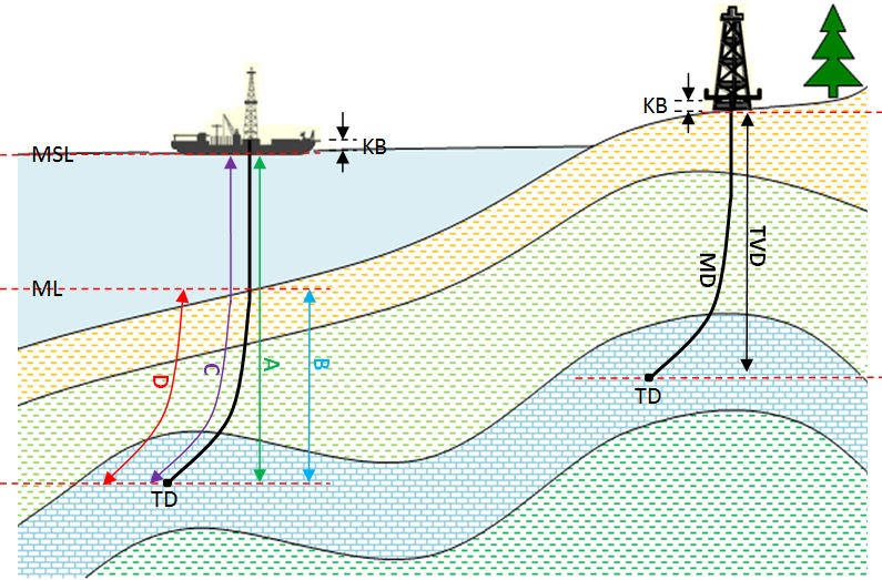
Because wells are not always drilled vertically, there may be two “depths” for every given point in a wellbore: the measured depth (MD) measured along the path of the borehole, and the true vertical depth (TVD), the absolute vertical distance between the datum and the point in the wellbore. In perfectly vertical wells, the TVD equals the MD; otherwise, the TVD is less than the MD measured from the same datum. Common datums used are ground level (GL), drilling rig floor (DF), rotary table (RT), kelly bushing (KB) and mean sea level (MSL). [1]
Kelly Bushing Height (KB):The height of the drilling floor above the ground level. Many wellbore depth measurements are taken from the Kelly Bushing. The Kelly bushing elevation is calculated by adding the ground level to the Kelly bushing height.
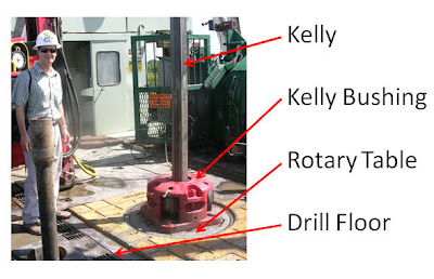
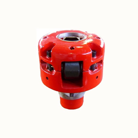
Kelly bushing is that elevated device positioned right on top of the rotary table and used to transmit torque from the rotary table to the kelly. The kelly bushing is designed to be the connection between the rotary table and the kelly. The kelly is a 4 or 6 sided steel pipe.
The purpose of the rotary table is to generate the rotary action (torque) and power necessary to rotate the drillstring and drill a well. The torque generated by the rotary table is useless if it is not transferred to the kelly (the drillstring is connected to the kelly).
Hence, through the kelly bushing the torque generated at the rotary table is transferred to the kelly. To achieve this connection, the inside profile of the kelly bushing matches the outer profile of the kelly so that the kelly fits or “sits” comfortably in the kelly bushing.
There are various designs for the kelly bushing including the split type, the pin-drive type and the square-drive type. Each of these designs has different ways in which they are connected and disconnected from the rotary table.
The internal diameter of the kelly bushing can be cut into the shape of a square (4-sided) or a hexagon (6-sided) depending on the outer shape of the kelly that will be used. The internals of a Kelly bushing is designed to resemble the outer shape of a Kelly just like the insides of a key lock is cut to exactly match the outer shape of the key.
The kelly bushing is not designed to hold tightly onto the Kelly; the kelly is still permitted to move up and down through the kelly bushing. This requirement is a must since drilling cannot progress if the kelly remains on a fixed spot. As the well is drilled deeper, the kelly also moves downward through the Kelly bushing.
The kelly bushing is sometimes used as a reference point from which depth measurements can be taken. All depths must be recorded with respect to a reference point; the kelly bushing (KB) is one of the depth references used in the oil and gas industry.
The top of the kelly bushing is normally used as the depth reference.For example, 7500ft KB means 7500ft below the kelly bushing or 7500ft measured from the top of the kelly bushing down to that point in the well.
In some other cases, depths could be recorded as 7500ft MDBKB meaning 7500ft measured depth below the kelly bushing. This is mostly used when the measured depth is different from the true vertical depth of the well, common with deviated and horizontal wells.
In most drilling operations the rotary table elevation is used as the working depth reference. The abbreviation BRT (below rotary table) and RKB (rotary kelly bushing) are used to indicate depths measured from the rotary table. This can also be referred to as derrick floor elevation. For floating drilling rigs the rotary table elevation is not fixed and hence a mean rotary table elevation has to be used.
Kelly Bushing Height (KB): The height of the drilling floor above the ground level. Many wellbore depth measurements are taken from the Kelly Bushing. The Kelly bushing elevation is calculated by adding the ground level to the Kelly bushing height.
1. n. [Drilling] An adapter that serves to connect the rotary table to the kelly. The kelly bushing has an inside diameter profile that matches that of the kelly, usually square or hexagonal. It is connected to the rotary table by four large steel pins that fit into mating holes in the rotary table.
A Kelly bushing (some people call “rotary Kelly bushing”) engages a master bushing via four pins and rollers inside a Kelly bushing to allow a Kelly to move up or down freely while it is rotated or in a static mode. This video demonstrates how to make a connection via a Kelly system.
Kelly bushing is that elevated device positioned right on top of the rotary table and used to transmit torque from the rotary table to the kelly. The kelly bushing is designed to be the connection between the rotary table and the kelly.
1. n. [Drilling] An adapter that serves to connect the rotary table to the kelly. The kelly bushing has an inside diameter profile that matches that of the kelly, usually square or hexagonal. It is connected to the rotary table by four large steel pins that fit into mating holes in the rotary table.
The kelly is used to transmit rotary motion from the rotary table or kelly bushing to the drillstring, while allowing the drillstring to be lowered or raised during rotation.
1. adj. [Drilling] Referring to the condition that occurs when the kelly is all the way down, so drilling progress cannot continue. A connection must be made, which has the effect of raising the kelly up by the length of the new joint of drillpipe added, so drilling can resume.
This means that Top Drives can drill about 90 feet before making a connection, whereas with a Kelly System, you will make a connection at about 30 feet deep. Another difference between a Kelly and a Top Drive is that a Top Drive System allows rotation and circulation while back reaming out of a hole.
Kelly drive system is capable to drill with one single drill pipe. On other hand TDS is capable to drill with drill pipe stand. One drill pipe stand is made of three drill pipe joints together.
Kelly bars operate by transferring the torque and crowd force from a rotary drive tool to the drilling tool. Many kelly bars can be applied to any type of piling rig that is available on the market. Kelly bars can be divided into two main types: friction kelly bars and interlocking kelly bars.
The wear bushing is housed in the head or in the spool and is secured by means of two tie down screws to protect it against damage or wear during drilling. It is installed or retrieved with either a simple installation tool or with the HCC combined tool.
Kelly Saver Subs refer to a sub used between the Kelly or top head drive and the drill pipe. It is usually a pin to pin sub that takes the wear abuse to protect the drill pipe and the drive connection. Mills can furnish these subs along with the fluted, hex, or square Kelly Bar drive itself.
A mechanical device for rotating the kelly. The kelly spinner is typically pneumatic. It is a relatively low torque device, useful only for the initial makeup of threaded tool joints. It is not strong enough for proper torque of the tool joint or for rotating the drillstring itself.
This means that Top Drives can drill about 90 feet before making a connection, whereas with a Kelly System, you will make a connection at about 30 feet deep. Another difference between a Kelly and a Top Drive is that a Top Drive System allows rotation and circulation while back reaming out of a hole.
Kelly bars are key components in the execution of boreholes with hydraulic rotary drilling rigs. They transfer the torque of the rotary drive and the crowd pressure of the crowd system concurrently to the drilling tool.
A kelly drive is a type of well drilling device on an oil or gas drilling rig that employs a section of pipe with a polygonal (three-, four-, six-, or eight-sided) or splined outer surface, which passes through the matching polygonal or splined kelly (mating) bushing and rotary table.
A conventional rotary rig or rotary table rig or kelly drive rig is a drilling rig where the rotation of the drill string and bit is applied from a rotary table on the rig floor.
Kelly drive system is capable to drill with one single drill pipe. On other hand TDS is capable to drill with drill pipe stand. One drill pipe stand is made of three drill pipe joints together.
Kelly bars operate by transferring the torque and crowd force from a rotary drive tool to the drilling tool. Many kelly bars can be applied to any type of piling rig that is available on the market. Kelly bars can be divided into two main types: friction kelly bars and interlocking kelly bars.
ROTARY TABLE MASTER BUSHING Filed oct. 22, 1965 4 sheets-sneer 4 BY a@ United States Patent O 3,386,263 ROTARY TABLE MASTER BUSHING Spencer W. Long, Inglewood, Calif., assiguor to Armco Steel Corporation, Middletown, Ohio, a corporation of Ohio Filed Oct. 22, 1965, Ser. No. 501,565 16 Claims. (Cl. 64I-23.5)
ABSTRACT OF THE DISCLOSURE The master bushing assembly for a well drilling rotary machine comprises duplicate split halves each having a laterally extending driving lug provided with a radial driving face, the master bushing halves each lbeing rovi-ded with axially extending pin sockets for reception of driving7 pin-s on a kelly bushing.
This invention relates to well drilling apparatus and is particularly directed to a novel -form of rotary table and bushings for turning the kelly and handling drill pipe.
In -conventional apparatus, the master bushing rests in the rotary table and is provided with a tapered bore to receive wedge-shaped pipe-gripping slips for engaging the outer surface of drill pipe. The master bushing is s-plit axially into two sections to `facilitate removal from the rotary table so that the maximum opening in the rotary table may be used when lowering the bit through the rotary table. The split master bushing is commonly yprovided with a square portion which is received within a square recess in the rotary table, so that the rotary table may turn the master bushing. The kelly drive bushing has been driven by a similar square recess in the master bushing, or by parallel downward extending drive pins. Drive pins on. the kelly bushing are often used when deep drilling operations require a long tapered bore in the master bushing to accommodate long drill pipe slips; in such case the tapered bore extends to the top surface of the master bushing, thereby preventing the use of a drive square in the master bushing.
Heretofore the drive pins on the kelly bushing have been successfully used only with solid master bushings. These solid master bushings have been used to provide accurate spacing for the drive pin sockets and to provide solid support for long drill pipe slips and heavy loads. Solid master bushings have the disadvantage of being awkward to handle, and being time-consuming to remove and replace when large diameter bits, tools, casing, etc. are to be lowered through the rotary table.
The principal object of this invention is to provide a split type master bushing which will remain firmly seated in the rotary table opening and maintain accurate location and spacing of pin sockets for kelly bushing drive pins under forces exerted when d-riving the kelly and which will rigidly support the slips when handling drill pipe. The master Ibushing has a circular shape with external diameters substantially equal to the central openings in the rotary table to provide solid .backing for drill pipe slips, and to maintain the pin drive sockets for the kelly bushing in accurate location. Each master bushing section has a single outward extending driving lug, and the conventional drive square is eliminated. The driving lugs and the sockets for the drive pins of the kelly bushing are so located on the .master bushing sections that the driving forces act to keep the bushing sections seated against the table opening and act to maintain accurate spacing of the drive pin sockets.
FIGURES 6, 7 and 8 are diagrammatic illustrations showing how the driving forces between the table `and the master bushing sections and between the ma-ster bushing sections and the kelly bushing are of .a direction and location to force the master bushing sections outward against the central opening in the rotary table.
FIGURES 9, 10 and 11 show similar force diagrams for a master bushing having a conventional square drive from the rotary table, and kelly bushing drive pin socket locations identical to those of FIGURES 6, 7 and 8.
A master bushing assembly generally designated 24 is split longitudinally to form a pair of duplicate master bushing sections 25 and 26 having confronting faces 27, 28 and 29, 30. The outer 4surfaces 31, 31a of the bushing sections are circular and they are adapted to be received and supported on the shoulder 23 joining the parts of the stepped central opening 17, 17a in the rotary table 12.
Each bushing section has a single driving lug 32, 33, extending outward beyond the outer surface of the bushing section and received in one of the drive pockets 18, 19. The driving lug 32 extends into pocket 18 between the radial wall 21 and the clearance wall 21a spaced therefrom, and is -provided with a radial face 34 for engagement with the radial wall 21 of the pocket 18. Similarly, the driving lug 33 extends into the pocket 19 between the radial wall 22 and the clearance wall 22a spaced therefrom, and has a radial face 35 which contacts the radial wall 22 of the pocket 19. When the parts are in the position shown in the drawings, the radial faces 34 and 35 of the driving lugs 32 and 33, the radial walls 21 and 22 of the table pockets 18 and 19, the radial face 27 of the bushing section 25 and radial face 30 of the bushing section 26 all lie in Vthe same vertical plane which passes through the rotary axis of the rotary table 12. The surface 29 on the bushing section 25 and the surface 28 on the bushing section 26 lie on opposite sides of this common plane and have a small clearance space therewith, which clearance space facilitates installation and removal of the bushing sections with respect to the rotary table 12.
The master bushing sections 25 and 26 cooperate to define a central tapered bore 37 for reception of wedgeshaped pipe-engaging slips, not shown. The central bore 37 extends to the upper surface of the master bushing and its taper portion is relatively long in order to accommodate the long slips employed for gripping heavy strings of pipe. A kelly bushing generally designated 39 is provided with a pilot skirt 40 which extends into the bore 37. The kelly bushing 39 rests on the upper surface of the master bushing 24 and is provided with rollers 41 which engage the faces of the kelly 38. The kelly bushing 39 is provided with four equally spaced downward extending parallel drive pins 42, and these drive pins are received in upward opening sockets 43, 44, 45, 46 provided on the master bushing 24. The pin sockets 43 and 44 are located on the bushing section 25 and the pin sockets 45 and 46 are located on the bushing section 26. Driving torque transmitted by the pinion 15 to the ring gear 14 causes the rotary `table 12 to drive the lugs 32 and 33 on the master bushing sections and these in turn drive the kelly bushing 39 through the drive pins 42. The rollers 41 apply driving torque to turn the kelly 38 while at the same time permitting it to move freely in a vertical direction.
The locations of the pin sockets 43, 44, 45 and 46 on the master bushing sections 25 and 26 are not symmetrical with respect to each bushing section but on the contrary the pin socket 43 is located close to the surface 29 on the bushing section 25, and the pin socket 45 is located close to the surface 28 on the bushing section 26. The pin socket 43 on the bushing section 25 is remote from the driving lug 32 on that same bushing section. Similarly, Vthe pin socket 45 on the bushing section 26 is remote from the driving lug 33 on the same bushing section. Pin socket 44 is located 90 degrees from pin socket 43, and similarly, pin socket 46 is located 90 degrees from pin socket 45.
FIGURES 6, 7 and 8 are force diagrams showing how this arrangement of drive lugs and sockets results in holding the master sections in solid engagement with the rotary table opening 17 under the driving forces imparted by the rotary table to the master bushing sections and by the master bushing sections to the kelly bushing 39. In FIGURE 6 the force P represents the driving force applied by the rotary table 12 to the driving lug 32 on the master bushing section 25. The force Q represents the driving reaction from a kelly drive pin 42 in the socket 44, assuming that all force between kelly bushing 39 and master bushing section 25 is taken by this particular socket. The force R is the reaction of the rotary table 12 against the master bushing section 25, resulting from the yforces P and Q. In FIGURE 7, force P is the same but the forces Q1 and Q2 assume that the sockets 44 and 43 are equally loaded. The force R1 represents the reaction of the rotary table 12 against the master bushing section 25 resulting from the forces P, Q1 and Q2. In FIGURE 8, the force P is the sarne and the force Q represents the driving reaction on the socket 43, assuming that this socket carries all of the force between kelly bushing 39 and master bushing section 25. The force R2 is the reaction of the rotary table 12 against the master bushing section 25 resulting from the forces P and Q. In all three views, FIGURES 6, 7 and 8, it is apparent that the reaction forces R, R1, Rzof the rotary table 12 against the master bushing section 25 are toward the axis of rotation and not away from it. In other words, the driving forces from the rotary table 12 and the driving reactions from the kelly bushing 39 are of a direction and location to force the master bushing section 25 outward against the circular bore in the rotary table 12. Since the bushing section 26 is a duplicate of the bushing section 25, the same forces and reactions occur and both bushing sections are held in solid engagement with the bore of the rotary table by reason of the driving forces and reactions. Although the force diagrams of FIGURES 6, 7 and 8 do not take into account the action of centrifugal force, such centrifugal force serves to supplement the action of maintaining the split master bushing sections 25 and 26 in contact with the circular opening in the rotary table 12.
The force diagrams of FIGURES 9, 10 and 11 show the distribution of driving forces on a split master bushing construction having conventional square driving faces and kelly bushing drive pin socket locations identical to those of FIGURES 6, 7 and 8. The conventional rotary table 12a has a square recess 50 in its upper surface and this recess has parallel faces 51 and 52 and parallel faces 53 and 54. The corners of the square are beveled olf to provide clearance spaces 55. The split master bushing sections 56 and 57 have a conventional square shape with the corners beveled away. In this construction, location of the pin sockets 43a and 44a in the same relative position as that shown in FIGURES 6, 7 and 8 does not result in holding the master bushing sections in solid engagement with the rotary table 12a in all cases. In FIGURE 9, it is assumed that all of the driving reaction -is taken by the socket 44a. This compares to FIGURE 6. In FIG- URE 10, it is assumed that half of the total driving reaction is taken by each socket 43a and 44a. This compares to FIGURE 7. In FIGURE 11, it is assumed that all of the driving reaction is taken by the socket 43a. In FIGURE 9 the driving force P1 would have to be equal to and colinear with driving reaction Q to prevent inward displacement of master bushing section 56 relative to rotary table 12a. Since angle A is much greater than the angle of friction for the contacting surfaces of master bushing section 56 and rotary table 12a, driving force P1 cannot be colinear with driving reaction Q. Hence in FIGURE 9 inward displacement of master bushing section 56 relative to rotary table 12a is not prevented. Since both centrifugal force on master bushing section 56 and driving reaction Q are variable, alternate inward and outward displacement of master bushing section 56 relative to rotary table 12a would occur, thereby causing misalignment and producing excessive wear. Inspection of the force diagram of FIGURE 10 reveals that a similar though not so pronounced tendency toward inward displacement of master bushing section 56 relative to rotary ta"ble 12a exists. No such tendency exists when all of the driving reaction between master bushing section 56 and kelly bushing 39 is taken by socket 43a as shown in FIGURE 11.
Due to manufacturing inaccuracies and wear of parts, the direction and location of the resultant forces will vary between the extremes shown in FIGURES 6, 7 and 8 for the device embodying this invention, and will vary between the extremes shown in FIGURES 9, 10 and 11 for the conventional square drive with kelly bushing drive pin sockets located as shown. With the split circular master bushing shown in FIGURES 6, 7 and 8, the driving forces and centrifugal force will always tend to hold the bushing sections outward against the opening in the rotary table, but with the construction shown in FIG- URES 9, 10 and l1, alternate inward and outward displacement of the master bushing sections 56 and 57 occurs within the rotary table drive recess 50.
From a consideration of the force diagrams of FIG- URES 6, 7, and 8, it is apparent that the maximum benets in maintaining each master bushing section in contact with the rotary table opening is achieved when the pin drive socket remote from the driving lug on that section is positioned as close as practicable to the confronting faces of the master bushing sections.
The sections 25 and 26 of the master bushing 24 may be removed separately from .the opening 17 in the rotary table 12, after the kelly bushing 39 and kelly 38 have been removed. As shown in FIGURE 2, openings 59 are provided in the upper surface of each master bushing section, and a pair of hooks on a sling (not shown) may be inserted into these openings. The location of the openings 59 is chosen so that tilting movement of each bushing is minimized when it is lifted by hooks inserted into these openings.
In order to facilitate installation and removal of the master bushing sections 25 and 26 with respect to the vrotary table 12, the outer wall 61 of each bushing section, which wall is otherwise circular, is provided with a straight portion 62 at a location remote from the driving lug on that bushing section. A clearance space 63 is thus formed between the short straight portion 62 and the circular opening 17 in the rotary table 12. This clearance space 63 insures that adequate clearance develops/ between the circular opening 17 and the outer circular wall 61 of the bushing section when the bushing section swings through a small arc around the corner 64 at the intersection of the opening 17 and the radial face of the driving lug.
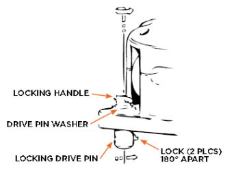
Means are provided for releasably latching the master bushing sections 2S and 26 against upward movement relative to the rotary table 12. As shown in FIGURE 3, this means includes a latch actuating pin 66 mounted to turn and slide vertically within aligned openings 67 and 68 on the bushing section 26. The latch pin 66 has an integral enlarged head 69 of non-circular outline and resting in the non-circular recess 70 provided in the upper surface of the bushing section. The pin 66 is slidably keyed to the latch element 71 which has a projecting portion 72 adapted to enter the latch recess 73 provided on the rotary table 12. When the latch is to be operated, the enlarged head 69 is grasped manually, lifted upward out of the recess 70, and then turned one-quarter turn. This moves the projecting portion 72 of the latch element 71 into or out of the latch recess 73. The head 69 is then allowed to descend by gravity back into the non-circular recess 70 to hold the latch element 71 in selected position. A weld bead 74 is provided to limit upward travel of the head 69 and latch pin 66.
In a modified form of the invention shown in FIGURES 12-15, the rotary table and the outer shape of the master bushing sections and the location of the pin drive sockets is the same as that previously described, but a split liner is provided within the central tapered bore dened by the master bushing sections. The master bushing sections are shown at 25a and 26a and each is provided with a single outward extending driving lug 32a and 33a as previously described. Split liner sections 75 and 76 are duplicates and are mounted within the central tapered bore 37a defined by the master bushing sections 25a and 26a. A positioning lug 77 on each liner section and a mating recess 78 on each master bushing section as shown in FIGURE l5 insures that the confronting faces 79 on the liner sections will always be perpendicular to the confronting faces 80 on the master bushing sections, This insures that both liner sections 75 and 76 must be removed from rotary table 12 before removing either master bushing section 25a or 26a, and thus any possibility of accidentally dropping the liner section down through the rotary table is eliminated.
When the liner sections 75 and 76 are removed, the tapered bore 37a in the master bushing sections may be employed with slips for handling large diameter pipe. A pair of hook receiving openings 81 are provided on each liner section to facilitate lifting it from the tapered bore in the master bushing sections. Also latch means are provided for latching the liner sections against upward movement relative to the master bushing sections. As shown in FIGURE 14, the latch element 71a is slidably keyed on the latch pin 66a so that when the latter is raised and turned by means of the enlarged head 69a the projecting portion 72a is swung into or out of the latch recess 73a.
rotary table having a central circular opening and having a pair of diametrically positioned pockets, each pocket having a radial wall and a clearance wall spaced .therefrom, a master bushing assembly having an outer circular surface mounted in said table opening, said master bushing assembly being split axially to forma pair of bushing sections having spaced confronting surfaces, each bushing section having a driving lug adjacent its confronting surface and extending outward beyond said surface into one of said pockets, respectively, and between the radial wall and clearance wall thereof, each of said lugs having a radial driving face engageable with one of said radial walls, respectively, and having another face spaced from one of said clearance walls, respectively.
2. In a well drilling device, the combination of: a rotary table having a central circular opening and having an upper surface provided with a pair of pockets diametrically positioned and extending into said opening, each pocket having a radial wall and a clearance wall spaced therefrom, a master bushing assembly having an outer circular surface mounted in said table opening, said master bushing assembly being split -axially to form a pair of duplicate bushing sections having spaced confronting surfaces, each bushing section having a driving lug adjacent its confronting surface and extending outward beyond said outer surface into one of said pockets, respectively, and between the radial wall and clearance wall thereof, each of said lugs having a radial driving face engageable with one of said radial walls, respectively, and having another face spaced from one of said clearance walls, respectively.
3. In a well drilling device, the combination of: a rotary table having a central circular opening and having a pair of diametrically positioned pockets, a master bushing assembly having an outer circular surface mounted in said table opening, said master bushing assembly being split axially by parallel offset plane surfaces to form a pair of duplicate bushing sections with clearance between said plane surfaces, each bushing section having a driving lug extending outward beyond said outer surface into one of said pockets, respectively, each of said lugs having a radial driving face forming a continuation of one of said plane surfaces.
4. In a well drilling device, the combination of: -a rotary table having a central circular opening and having an upper surface provided with a pair of pockets diametrically positioned and extending to said opening, each pocket having a radial wall, a master bushing assembly having an outer circular surface mounted in said table opening, said master bushing assembly being split axially by parallel offset plane surfaces to form a pair of duplicate bushing sections with clearance between said plane surfaces, each bushing section having a driving lug extending outward beyond said outer surface into one of said pockets, respectively, each of said lugs having a radial driving face forming a continuation of one of said plane surfaces and engageable with one of said radial walls, respectively.
5. In a well drillin-g device, the combination of: a rotary table having a central circular opening and having a pair of diametrically positioned pockets, each pocket having a radial wall, a master bushing assembly having an outer circular surface mounted in said table opening, said master bushing assembly being split axially to form a pair of duplicate bushing sections with confronting surfaces, each bushing section having a driving lug extending outward beyond said outer surface into one of said pockets, respectively, each of said lugs having a radial driving face engageable with one of said radial walls, respectively, the outer circular surface of each master bushing section being relieved at a location adjacent a confronting surface and remote from the lug on that master bushing section, whereby clearance spaces are formed within the circular opening of the rotary table to facilitate removal of the master bushing sections from the rotary table opening.
rotary table having a central circular opening and having a pair of diametrically positioned pockets, each pocket having a radial wall, a master bushing assembly having an outer circular surface mounted in said table opening and having a central bore, said master bushing assembly being split axially to form a pair of duplicate bushing sections with confronting surfaces, each bushin-g section having a driving lug extending outward beyond said outer surface into one of said pockets, respectively, each of said lugs having a radial driving face engageable with one of said radial walls, respectively, a liner having a taper bore and mounted in the central bore of the master bushing assembly, the liner being split axially to form duplicate liner sections with confronting surfaces, and interengaging means on the liner and master bushing sections acting to maintain the confronting surfaces of the liner at right angles to the confronting surfaces on the master bushing sections.
7. For use with a well drilling rotary table, having a central circular opening, the combination of: a master bushing assembly having a circular outer surface for reception in the circular opening o-f the table, said master bushing assembly being split axially by parallel offset plane surfaces to form a pair of duplicate bushing sections with clearance between said plane surfaces, each bushing section having a driving lug extending outward beyond said outer circular surface and having a radial driving face forming a continuation of one of said plane surfaces.
8. For use with a well drilling rotary table having a central circular opening, the combination of: a master bushing assembly having a circular outer surface for reception in the circular table opening, said master brushing assembly being split axially to form a pair of duplicate bushing sections having confronting surfaces, each bushing section having a driving lug extending out-ward beyond said outer circular surface and having a radial driving face forming a continuation of one of the confronting surfaces, the outer circular sur-face of each master bushing section being relieved at a location adjacent a confronting surface and remote from the lug on that master bushing section, whereby clearance spaces are formed within the circular opening of the rotary table to facilitate removal of the master bushing sections from the rotary table opening.
9. For use with a well drilling rotary table having a central circular opening, the combination of: a master bushing assembly having an outer surface for reception in the table opening and having a central bore, said master bushing assembly bein-g split axially to lform a pair of duplicate bushing sections, each bushing section having a drivin-g lug extending outward beyond said outer surface and having a radial driving face adjacent one of the confronting surfaces, a liner having a taper bore and mounted in the central bore of the master bushing assembly, the liner` being split axially to `form duplicate liner sections with confronting surfaces, and interengaging means on the liner and master bushing sections acting to maintain the confronting surfaces of the liner at right angles to the confronting surfaces on the master bushing sections.
10. In a well drilling device, the combination of: a rotary table having a central circular opening, a master bushing assembly having an outer circular surface mounted in said table opening, said master bushing assembly being split axially to form a pair of bushing sections, means for driving each master bushing section from said table, a kelly bushing having four parallel downward extending equally spaced driving pins, said master bushing sections each having two pin sockets for reception of said driving pins, one of said pin sockets on each bushing section lying substantially closer than the other pin socket to the other bushing section.
11. In a well drilling device, the combination of: a rotary table having a central circular opening, a master bushing assembly having an outer circular surface mounted in said table opening, said master bushing assembly being split axially to form a pair of duplicate bushing sections having confronting surfaces, means for driving each bushing section from said table, a kelly bushing having four parallel downward extending equally spaced driving pins, said master bushing sections each having two pin sockets for reception of said driving pins, one of said pin sockets on each bushing section lying substantially closer than the other pin socket to said confronting surfaces.
12. In a `well drilling device, the combination of: a rotary table having a central circular opening and having a pair of diametrically positioned pockets, a master bushing assembly having an outer circular sur-face mounted in said table opening, said master bushing assembly being split axially to form a pair of duplicate bushing sections having confronting surfaces, each bushing section having a driving lug extending outward beyond said outer surface into one of said pockets, respectively, a kelly bushing having four parallel downward extending equally spaced driving pins, said master bushing sections each havin-g two pin sockets for reception of said driving pins, one of said pin sockets on each bushing section lying substantially closer than the other pin socket to said confronting surfaces.
rotary table having a central circular opening and having an upper surface provided with a pair of pockets diametrically positioned and extending to said opening, each pocket having a radial wall, a master bushing assembly having an outer circular surface mounted in said table opening, said master bushing assembly being split axially to form a pair of duplicate bushing sections having confronting surfaces, each bushing section having a driving lug extending outward beyond said outer surface into one of said pockets, respectively, each lug having a radial driving face engaging one of said radial walls, respectively, a kelly bushing having four parallel downward extending equally spaced driving pins, said master bushing sections cach having two pin sockets -for reception of said driving pins, one of said pin sockets on each bushing section being positioned adjacent to said confronting surfaces, and the other pin socket on each bushing section being remote from said confronting surfaces.
14. For use with a well drilling rotary table having a circular central opening, the combination of: a master bushing assembly adapted for reception in the table opening, said master bushing assembly having an upper sur- -face provided with four equally spaced upward opening parallel pin sockets, said master bushing assembly being split axially to form a pair of bushing sections, each with two of said pin sockets, one of said pin sockets on each master bushing section lying substantially closer than the other pin socket to the other bushing section, and each master bushing section having means whereby it may be driven from the rotary table.
15. For use with a well drilling rotary table having a circular central opening, the combination of: a master bushing assembly adapted for reception in the table opening, said master bushing assembly having an -upper surface provided with four equally spaced Iupward opening pin sockets, said master bushing assembly being split axially to form a pair of duplicate bushing sections having confronting surfaces, each master bushing section having two of said pin sockets, one of said pin sockets on each master bushing section lying substantially closer than the other pin socket to said confronting surfaces, and each master bushing section having means whereby it may be driven from said rotary table.
16. For use with a well drilling rotary table having a circular central opening, the combination of: a master bushing assembly adapted for reception in the table opening, said master bushing assembly having an upper surface provided with four equally spaced upward opening pin sockets, said master bushing assembly being split axially to form a pair of duplicate bushing sections having confronting surfaces, each bushin-g section having an outward extending driving lug adjacent said confronting surfaces whereby the bushing section may be driven from 1,892,690 1/ 1933 Witkin 64-23.5 the rotary table, each master bushing section having two 1,976,057 10/ 1934 Zilen 64-23.7 of said pin sockets, one of said pin sockets on each bush- 2,075,028 3/ 1937 Driscoll 64-23.5 ing section lying remote =from the driving lug and sub- 2,183,012 12/ 1939 Davidson 64-23.5 stantially closer than the other pin socket to said con- 5 2,204,645 6/ 1940 Baash 64-23.5 fronting surfaces. 2,306,130 12/1942 Long 64-23.7 2,344,746 3/ 1944 Spalding 64-23.5

These portable structures make great car/truck garages, greenhouses, sheds, workshops, storage buildings as well as outfitters tents. Our portable garages are 12’ wide and come in 12’, 18’, 24’, and 30’ lengths. The peak height measures 8’ and the wall height is 6’-6”.
A kelly drive is a type of well drilling device on an oil or gas drilling rig that employs a section of pipe with a polygonal (three-, four-, six-, or eight-sided) or splined outer surface, which passes through the matching polygonal or splined kelly (mating) bushing and rotary table. This bushing is rotated via the rotary table and thus the pipe and the attached drill string turn while the polygonal pipe is free to slide vertically in the bushing as the bit digs the well deeper. When drilling, the drill bit is attached at the end of the drill string and thus the kelly drive provides the means to turn the bit (assuming that a downhole motor is not being used).
The kelly is the polygonal tubing and the kelly bushing is the mechanical device that turns the kelly when rotated by the rotary table. Together they are referred to as a kelly drive. The upper end of the kelly is screwed into the swivel, using a left-hand thread to preclude loosening from the right-hand torque applied below. The kelly typically is about 10 ft (3 m) longer than the drill pipe segments, thus leaving a portion of newly drilled hole open below the bit after a new length of pipe has been added ("making a connection") and the drill string has been lowered until the kelly bushing engages again in the rotary table.
The kelly hose is the flexible, high-pressure hose connected from the standpipe to a gooseneck pipe on a swivel above the kelly and allows the free vertical movement of the kelly while facilitating the flow of the drilling fluid down the drill string. It generally is of steel-reinforced rubber construction but also assemblies of Chiksan steel pipe and swivels are used.
The kelly is below the swivel. It is a pipe with either four or six flat sides. A rotary bushing fits around the flat sides to provide the torque needed to turn the kelly and the drill string. Rollers in the bushing permit the kelly free movement vertically while rotating. Since kelly threads would be difficult to replace, normally the lower end of the kelly has saver sub — or a short piece of pipe — that can be refurbished more cheaply than the kelly. Usually, a ball valve, called the lower kelly cock, is positioned between the kelly and the kelly saver sub. This valve is used for well control if the surface pressure becomes too high for the rotary hose or surface conditions.
According to the ″Dictionary of Petroleum Exploration, Drilling and Production″, ″[The] kelly was named after Michael J. (King) Kelly, a Chicago baseball player (1880-1887) who was known for his base running and long slides.″


 8613371530291