
derrick floor versus kelly bushing quotation

Figure 8.06 shows a schematic diagram of a typical top-drive rig. In a top-drive drilling rig, the top-drive (Item 6 in Figure 8.06) is suspended from the traveling block (Item 5 in Figure 8.06) and attached to a guide system (gear train and rail system) on the derrick. The top-drive is an electrical motor that has the ability to travel vertically up and down and to impart torque to the drill pipe. These drilling rigs began to appear in the late 1990s. Although the top-drive supplies the torque for the system, a rotary table is still used to supply stability to the drill string and as a redundant (back-up) rotary system.
As we saw in our discussion of a Conventional Rotary Table Rigs, the next 30-foot joint of drill pipe to be added to the drill string is temporarily stored in the mousehole on the rig floor. This joint of drill pipe is added to the drill string when drilling ahead or tripping into the wellbore. Tripping is the process of running drill pipe into or out of the hole for purposes other than drilling ahead. For example, if a drill bit needs to be changed due to wear, then the entire drill string needs to be pulled from the wellbore (tripping out of the hole), the drill bit needs to be replaced, and the drill string needs to be run back into the wellbore (tripping into the hole) to resume normal drilling operations. You can imagine how much ineffective rig time (in terms of not drilling ahead) is used tripping into or out of the wellbore and making or breaking connections in the drill string–particularly if the well"s TD (Total Depth) is 10,000–15,000 feet (or a shallower well has a 10,000-foot horizontal section).
The improved efficiencies coming from a top-drive is that an entire 90-foot stand (or triple) of drill pipe can be connected to the drill string rather than a single 30-foot joint. This is because the top-drive can go to the full height of the derrick using the traveling block to connect to the entire stand of drill pipe. Note, however, that not all top-drives use a triple when connecting drill pipe; some use a Double (two joints), while others use a single joint from a mousehole.
Figure 8.07: Rig Components - showing Kelly, Kelly Bushing, Rotary Table, Mousehole, and Rat Hole (screen capture at 9 seconds of the Drilling Training video)
In the screen capture shown in Figure 8.07, we see many of the components discussed in this lesson: the kelly, kelly bushing, rotary table, mousehole, and rat hole. Throughout the video, you can see these components of the rig used in action.
In the screen capture shown in Figure 8.09, we see the mechanical tongs (red). As shown in the video, the mechanical tongs are used to grip the kelly and drill string to aid in uncoupling (unscrewing) the two.
At around 2:52 into the video, it appears that while two of the roughnecks were trying to remove the slips from the master bushing, the hoist system on the derrick was attempting to assist them by lifting the kelly and drill pipe to release pressure from the slips. Instead of freeing the slips, the hoist appears to have lifted the entire section of the rig floor covering the rotary table, along with the two roughnecks. You can hear someone laughing in the video.
At around 3:31 into the video, one of the roughnecks and the hoist appear to use a piece of drill pipe to tamp the section of rig floor back into place. This piece of drill pipe is then placed into the mousehole as the next piece of drill pipe to be connected to the drill string. This is not a standard operating procedure on the rig floor. After this incident, you can see the rotary table and kelly bushing rotating in the manner discussed in these lesson notes.
The Making a connection on a top drive triple from the derrick YouTube clip (3:26) is of a Derrickman (discussed earlier in this lesson) making connections on a top-drive rig from the perspective of the monkey board (Item 4 in Figure 8.06).
In this video, the derrickman appears to be connecting Triples (I think that I count three joints of drill pipe looking downward to the rig floor). As I mentioned, this video is taken from the monkey board on the top of the derrick.

Because wells are not always drilled vertically, there may be two “depths” for every given point in a wellbore: the measured depth (MD) measured along the path of the borehole, and the true vertical depth (TVD), the absolute vertical distance between the datum and the point in the wellbore. In perfectly vertical wells, the TVD equals the MD; otherwise, the TVD is less than the MD measured from the same datum. Common datums used are ground level (GL), drilling rig floor (DF), rotary table (RT), kelly bushing (KB) and mean sea level (MSL). [1]
Kelly Bushing Height (KB):The height of the drilling floor above the ground level. Many wellbore depth measurements are taken from the Kelly Bushing. The Kelly bushing elevation is calculated by adding the ground level to the Kelly bushing height.
Driller’s Depth below rotary table (DDbrt): The depth of a well or features within the wellbore as measured while drilling. The measured length of each joint of drillpipe or tubing is added to provide a total depth or measurement to the point of interest. Drillers depth is the first depth measurement of a wellbore and is taken from the rotary table level on the rig floor. In most cases, subsequent depth measurements, such as those made during the well completion phase, are corrected to the wellhead datum that is based on drillers depth (reference: Schlumberger Oilfield Glossary).
2. Set the drillpipe slips, break out the kelly and set the kelly back in the rat-hole (another hole in the rig floor which stores the kelly and swivel when not in use)
4. Latch the elevators onto the top connection of the drillpipe, pick up the drillpipe and remove the slips. Pull the top of the drillpipe until the top of the drillpipe is at the top of the derrick and the second connection below the top of the drillpipe is exposed at the rotary table. A stand (3 joints of pipe) is now exposed above the rotary table
Because wells are not always drilled vertically, there may be two "depths" for every given point in a wellbore: the borehole, and the datum and the point in the wellbore. In perfectly vertical wells, the TVD equals the MD; otherwise, the TVD is less than the MD measured from the same datum. Common datums used are ground level (GL), drilling rig floor (DF), Rotary table (RT), kelly bushing (KB or RKB) and mean sea level (MSL).
The term "subsea" (SS) by itself should not be used, as it is ambiguous. It could mean: below sea floor or bottom, below mean sea level (MSL), below lowest astronomical tide (LAT), etc.
The acronym TVDSS is commonly used in the oil industry to represent TVD minus the elevation above mean sea level of the depth reference point of the well. The depth reference point is the kelly bushing in the United States and a few other nations, but is the drill floor in most places.
Petrophysicists and drilling operations tend to express depths with reference to the rotary table or the original drill floor; geologists tend to use a common datum such as the mean sea level; geophysicists use the mean sea level. This can introduce much confusion when a unit is not specified with all 3 components: unit, path, and reference.
Common references used in operations include: Rotary Table (RT), Drill Floor (DF), Kelly Bushing (KB), Sea Bottom (SB), Ground Level (GL), Casing Bowl Flange (CBF).

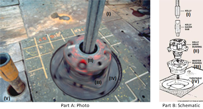
Rotary drilling rigs for forming boreholes require a rotary table centrally positioned on the floor of the drilling rig. The rotary table has a rotating center which receives a kelly bushing therein which imparts rotation into a kelly. The kelly is free to slide within the bushing and has a string of drill pipe connected at the lower end and a swivel at the upper end thereof.
The rotating table center and kelly bushing usually have bolt heads, fastener heads, and various other protrusions as well as various different indentions formed thereon. This is especially so on the older rotary drilling rigs.
The roughnecks working on the confined floor of a drilling rig must handle cables, chains, ropes, water hoses, and various hand and power tools. All of this is carried out in an extremely small floor area and from time to time a tool will inadvertently fall onto the rotating table center and centrifugal force throws the tool outwardly where it may strike a workman.
Accordingly, it is advantageous and highly desirable to encapsulate the rotary table of a drilling rig so as to isolate this dangerous area from the workmen so that should one accidently drop anything on the rig floor, it cannot possibly be caught in the rotating center.
This invention relates to drilling rig safety equipment, and specifically to a guard for a rotary table and a kelly, such as may be found on a rotary drilling rig or a workover unit. The guard of this invention has a lower end in the form of a flat circular show member from which there upwardly extends a wall member. The upper end of the wall member terminates at a bearing means. The bearing means is spaced from and concentrically arranged respective to the shoe, and has a rotatable part which slidably receives a marginal length of the kelly therethrough. The rotating kelly rotates the rotatable part of the bearing while the remainder of the bearing means remains stationary. Hence, the guard encapsulates the most dangerous parts of the rotary table and kelly and prevents extraneous items from falling into contact therewith.
This invention relates to a rotary table and kelly bushing guard for use in conjunction with a drilling rig, workover rig, or the like. In drilling boreholes, the massive rotary table, kelly, and kelly bushing are exposed in the center of the greatest activity of the drilling operation. From time to time, a roughneck will inadvertently catch a hose or chain or the like in the rotating mass, whereupon he often is violently thrown into the apparatus and fatally injured. Accordingly, the apparatus of the present invention isolates this dangerous mechanism from the surrounding area so that extraneous material cannot inadvertently come into contact therewith.
As seen in FIG. 1, a derrick floor 10 of a rotary drilling rig includes the non-rotating, circumferentially extending floor area 12 which overlies a rotary mechanism 14. The mechanism imparts rotation into a kelly bushing 16 by means of a drive sprocket 18 connected to the end of a pinion shaft of the rotary device. The kelly 20 is slidably received in a telescoping manner through the kelly bushing 16 in the usual manner, while drive mechanism 22 removably receives the kelly bushing 16 in the usual manner. As mechanism 16, 20, and 22 rotate respective to the fixed floor 12, there is a danger area 24" which must be avoided. There is always the grave danger that someone will somehow or another slip and fall into the danger area and thereby become severely injured.
In order to obviate this catastrophe, a rotary table and kelly bushing guard 24, made in accordance with the FIGS. 2--11 of the present invention, is slidably received about the kelly 20, thereby encapsulating the dangerous rotating mechanism of the drilling rig. The guard 24 includes an upper member in the form of bearing means 26 which slidably receives the rotating kelly therethrough. A heavy rubber shoe 28 forms a lower support member and is supported by the non-rotating area located outwardly of the rotary table, while a mid-portion 30 in the form of a circumferentially extending wall interconnects the bearing means 26 with the shoe 28.
As seen in FIGS. 6 and 8, together with other figures of the drawing, the bearing means includes Teflon rotatable member 36 within which there is formed an axial passageway 38 which slidably mates and rotates with the kelly 20. Bearing housing 40 is of annular configuration and preferably has the upper marginal end of ribs 32 molded therewithin. Washer 42 is split as indicated at 43 and is removably affixed to the fixed housing 40 by means of a plurality of fasteners 44 so that the rotating member 36 is captured in low friction relationship within the non-rotating member 40. This expedient enables the rotating member 36 to slidably receive and rotate with kelly 20 while non-rotating member 40 is held in a non-rotatable manner respective to the derrick floor and to the mid-portion 30.
Ribs 32 downwardly extend from the fixed upper housing member 40, as indicated by numeral 46. Member 36 is split into portions 48 and 50 so that the spaced fastener means 52 can be utilized for assembling the apparatus onto the kelly. Numeral 54 is the interface formed between the two members. The fasteners are received through apertures 56 and can include self-locking nuts and the like as may be desired.
In operation, fasteners 44 are removed to permit the two halves of washer 42 to be removed from the Teflon bearing assembly located at the upper end of the safety guard 24. Fasteners 52 are removed in order to split the rotating bearing member into halves 48 and 50 thereby facilitating assembly. The halves are placed about the kelly in the illustrated manner of FIG. 2. Stop member 25 preferably is a clamp device smaller in diameter than the pin or threaded male end of the kelly, and is tapered at the lower end to facilitate entrance through the kelly bushing and into the rat hole. The clamp holds the guard in the illustrated position of FIG. 3.
Bearing member 36 slidably engages the kelly for axial movement so that the kelly can continuously move in a downward direction as drilling progresses. When the kelly is lifted from the rotating table, the bearing means 36 of the protector device of the present invention engages the stop 25 and is lifted therewith in the manner of FIG. 3 so that another joint of drill pipe can be added to the drill string.
Hence, the rotating Teflon bearing axially slides respective to the kelly and captures the kelly therewithin so that it is rotated therewith. The heavy plastic guard cover 30 is nonrotatable and does not turn during kelly operation. The guard cover prevents one from inadvertently falling or stepping onto the rotary table, and furthermore prevents objects such as chains or hoses or ropes from catching the rotary table or kelly, and being wound thereabout, causing possible injury to adjacent personnel.
The heavy rubber shoe is located at the lower end of the safety guard. The shoe is provided with the illustrated small inside diameter 68 which forms a heel and tapers in an outward direction and terminates in a toe at large outside diameter 72. The bottom of the shoe is seen at 70. The marginal lower end of members 32 are imbedded within the shoe as noted by the numeral 74. This configuration forms a low profile so that a roughneck will not inadvertently stump his toe on the shoe. The present invention can be used in conjunction with any type of drilling or workover unit having a rotary table thereon. The non-rotating slidable safety guard of the present invention can be made of plastic, fiberglass, rubber, or metal, as shown in FIGS. 2 and 4. The safety guard can be left on the kelly and need not be removed for extended periods of time.
The center of the rotating bearing 36 can be made square as illustrated or hexagon to accommodate a hex shaped kelly as well as being made in other configurations for accommodating any other type kelly.

During the first phase of the development of the well, a rotary drilling rig is installed to bore a hole in the ground and reach the oil reservoir. The main rotary drilling rig components are derrick or mast, power and prime movers, hoisting equipment, rotating component, circulating system, tubular and tubular handling equipment and bit.
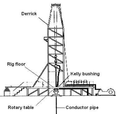
Derrick is mainly used offshore and is a large load-bearing vertical structure, usually of bolted construction and pyramidal in shape, for the equipment used to lower and raise the drill string into and out of the wellbore. The height of the derrick does not affect its load-bearing capacity, but it shows the maximum length of the drill pipe section. The standard derrick has square-shaped rig floor with four legs standing at the corners of the substructure. It provides work space for the necessary equipment on the rig floor.
Mast is mainly used with onshore rigs and is a portable derrick that can be raised as unit but for the transporting can be divided into two or more sections. It is usually rectangular or trapezoidal in shape.
Crown block is fixed assembly of sheaves (single or double) with a wire rope drilling line running between it and is located at the top of the derrick or mast and over which the drilling line is threaded. It is used to change the direction of pull from the drawworks to the traveling block.
Traveling block and hook combination is used to safely and efficiently raise or lower tools and equipment in the well. It is the set of sheaves or pulleys through which the drill line (wire rope) is threaded or reeved, is opposite the crown block and enabling heavy loads to be lifted out of or lowered into the wellbore. Hook is located beneath the traveling block and is used to pick up and secure the swivel and Kelly.
Drill line is the wire rope used to support the drilling tools. It is threaded or reeved through the traveling block and crown block to facilitate the lowering and lifting of the drill string into and out of the borehole. Drill line then clamped to the rig floor by the deadline anchor.
Rotating component is the equipment responsible for rotating the drill string. It consists of the swivel, Kelly spinner, Kelly or top drive, Kelly bushing, master bushing and rotary table (Figure 5).Swivel is a mechanical device that is hung from the hook of the traveling block to support the weight of the drill string and allows it to rotate freely. It provides connection for the rotary hose as well as passageway for the flow of drilling fluid into the drill stem.
Kelly is the heavy steel square or hexagonal member that is suspended from the swivel through the rotary table and connected to the topmost joint of drill pipe to turn the drill stem as the rotary table turns. It has a hole drilled through the middle that permits fluid to be circulated into the drill stem and up the annulus or vice versa. The Kelly goes through the Kelly bushing, which is driven by the rotary table.
Top drive is a hydraulically powered device on the drilling rig and is located at the swivel place. It allows the drill stem to spin and facilitate the process of drilling a borehole. Top drive means a power swivel, which directly turns the drill string without need for a Kelly and rotary table.
Kelly bushing is a device that fits into a part of rotary table called master bushing, transmits torque to the Kelly and simultaneously permits vertical movement of the Kelly to make hole. The Kelly bushing as Kelly is square or hexagonal and has an inside profile matching the Kelly’s outside profile with slightly larger dimensions so that the Kelly can freely move up and down inside.
Master bushing is a tool that fits into the rotary table of a drilling rig to accommodate the slips and drive the Kelly bushing so that the rotating motion of the rotary table can be transmitted to the Kelly.
Rotary table is section of the drill floor used to turn the drill stem. It has a beveled gear arrangement to create the rotational motion and opening into which bushings are fitted to drive and support the drilling assembly.
Circulating component is the rig equipment responsible for the movement of drilling fluid within the well as well as solids removal incurred by the drilling fluid (Figure 6). Normally, the circulation would start from the mud pits or tanks that are located besides the rig. Powerful pumps force the drilling through the surface high-pressure connections to a set of valves called pump manifold, located at the derrick floor. Then, the fluid goes up the rig within a pipe called standpipe to approximately 1/3 of the height of the mast. From there, the drilling fluid flows through a flexible high-pressure rotary hose to the top of the drill string. The flexible hose allows the fluid to flow continuously as the drill string moves up and down during normal drilling operations. The fluid enters in the drill string through a special piece of equipment called swivel located at the top of the Kelly. The swivel permits rotating the drill string while the fluid is pumped through the drill string. In wellbore, the drilling fluid then floes down the rotating string and jets out through the nozzles in the drill bit at the bottom of the hole. Drilling fluid carrying the drilled cuttings and flows out the center of the drill bit and is forced back up the outside of the drill pipe between the drill string and walls of the well (annular) onto the surface of the ground where it is cleaned and circulated back to the well. The cleaning process starts from the shale shaker, which is basically a vibrating screen. This will remove the larger particles, while allowing the residue to pass into settling tanks. The finer material can be removed using other solids removal equipments such as desander and desilter. If the mud contains gas from the formation, it will be passed through a degasser that separates the gas from the liquid mud. Having passed through all the mud processing equipment, the mud is returned to the mud pits or tanks for recycling.
Iron roughneck is a pneumatically operated machine that replaces the functions performed by the Kelly spinner, drill pipe spinner and tongs and is used to connect and disconnect tubular.


 8613371530291