
definition kelly hose manufacturer

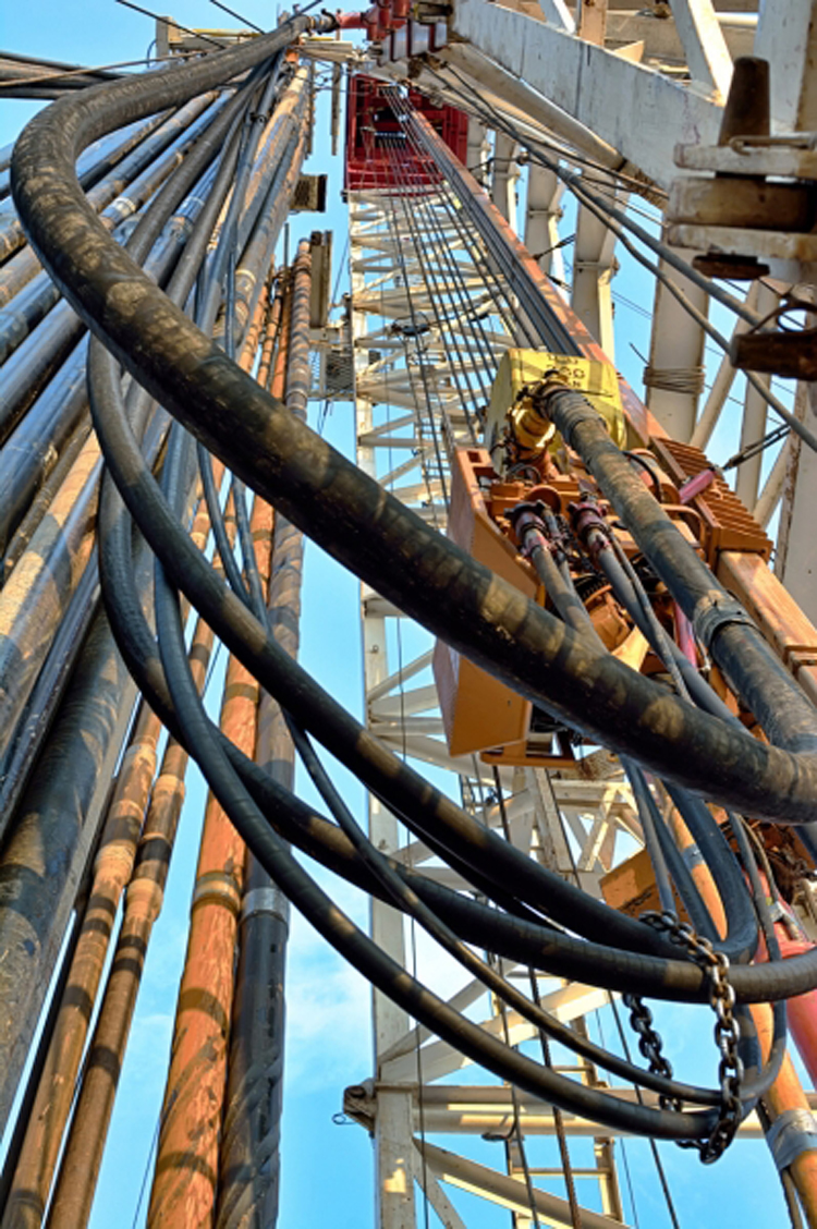
A large-diameter (3- to 5-in inside diameter), high-pressure flexible line used to connect the standpipe to the swivel. This flexible piping arrangement permits the kelly (and, in turn, the drillstring and bit) to be raised or lowered while drilling fluid is pumped through the drillstring. The simultaneous lowering of the drillstring while pumping fluid is critical to the drilling operation.
Flexible drilling rubber hoses play an important role in petroleum extraction. They should suffer high operating pressure, extreme operating temperature, abrasion and other inferior elements. Our special compounded synthetic rubber has been proven an effective and economical way to reject these problems. All our oilfield drill hoses are manufactured as API 7K or other related specifications.
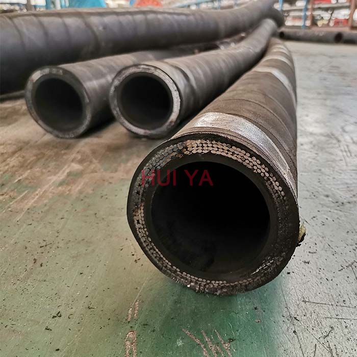
Steel cable reinforcement loads most working pressure up to 15,000psi. The wires are usually zinc-plating or copper platting to improve steel wire resistant against rust and corrosion. Due to the thick reinforcement, the hoses should be handled or stored in correct way to avoid kicking or crushing. They will substantially decrease their rated operating pressure.
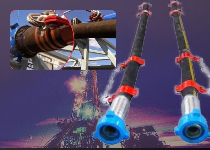
Rotary hose, Kelly hose, cement hose, mud hose, jumper hose and vibrator hose and choke & kill hoses are the most popular oilfield rubber hoses. They convey high-pressure drilling fluid from one place to another. Many end fittings are provided to satisfy different applications. Most end fittings are made according to API standards. Special order is also available.
A rotary/pumper hose is used in oil well drilling. It acts as the crucial instrument in the connection being made between the standpipe and the swivel.
A rotary hose is also used as a means of permitting the kelly to be either raised or lowered through the drilling process while also allowing the drill bit to be raised with the drillstring. For this reason, it is also often referred to as a “kelly hose.”
Rotary hoses also function during the process that allows the drilling fluid to be pumped through the hose when the bit and drillstring are raised and lowered.
This process is imperative in the completion of the drilling process. The drillstring portion of the drilling line and the connection to the rotary hose is thus crucial.
A large-diameter (3- to 5-in inside diameter), high-pressure flexible line used to connect the standpipe to the swivel. This flexible piping arrangement permits the kelly (and, in turn, the drillstring and bit) to be raised or lowered while drilling fluid is pumped through the drillstring. The simultaneous lowering of the drillstring while pumping fluid is critical to the drilling operation.
Made of heavy rubber and steel cables the hose is basicly flexible piping that allows the Kelly and the bit and drill string to be raised and lowered while the drilling fluid is pumped through drill string.
lowering the drill string and pumping drilling mud is very important to the drilling process and when these hoses go down or fail in service a entire rig can shut down.
Made of heavy rubber and steel cables the hose is basicly flexible piping that allows the Kelly and the bit and drill string to be raised and lowered while the drilling fluid is pumped through drill string.
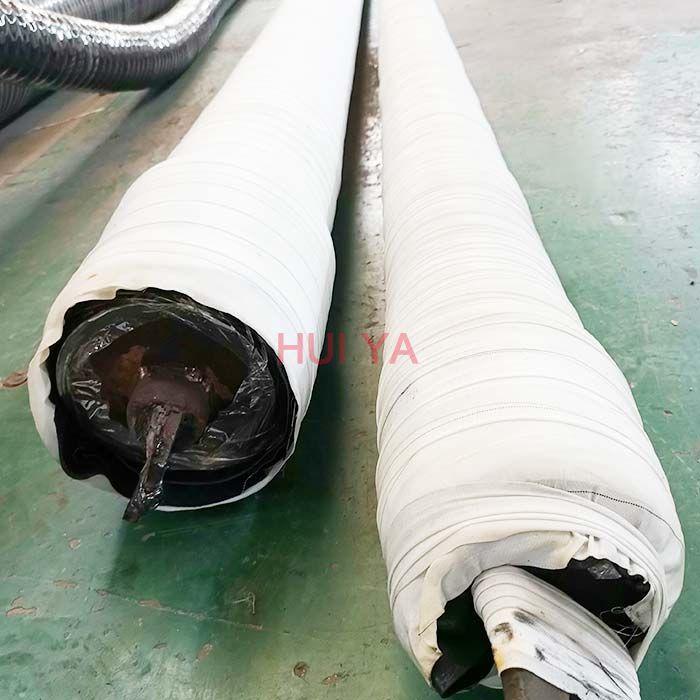
Rotary Drilling/Pumper hose is mainly used for conveying water-based or oil-based mud and other fluids in the working temperature of -30 °C to +82 °C.
The reinforcement is made from 2-8 layers of high tensile and high strength spiraled steel wire, making the hose have solid structure and resistant to high pressure.
The cover is made from high quality synthetic rubber, mainly chloroprene rubber, making the hose resistant to abrasion, corrosion, cut, weather, ozone, aging and sunlight.
A Kelly hose (also known as a mud hose or rotary hose) is a flexible, steel reinforced, high pressure hose that connects the standpipe to the kelly (or more specifically to the goose-neck on the swivel above the kelly) and allows free vertical movement of the kelly while facilitating the flow of drilling fluid through the system and down the drill string.
Flexible drilling rubber hoses play an important role in petroleum extraction. They should suffer high operating pressure, extreme operating temperature, abrasion and other inferior elements. Our special compounded synthetic rubber has been proven an effective and economical way to reject these problems. All our oilfield drill hoses are manufactured as API 7K or other related specifications.
Steel cable reinforcement loads most working pressure up to 15,000psi. The wires are usually zinc-plating or copper platting to improve steel wire resistant against rust and corrosion. Due to the thick reinforcement, the hoses should be handled or stored in correct way to avoid kicking or crushing. They will substantially decrease their rated operating pressure.
We are global leader in the design, manufacture and supply of high pressure hoses.As drilling operation methods evolve, become deeper, with increasing pressure and higher temperatures,
We have over 50 years of experience in metallic reinforced bonded elastomer hoses and has been the first company to obtain certification for all three governing industry standards: API 7K, 16C and 17K standard.
We have since built up a broad portfolio for a variety of drilling applications, such as flexible choke & kill Lines, rotary & vibrator hoses, managed pressure drilling hoses to meet the needs of both onshore & offshore drillers and distributors.
Our key offering includes rotary drilling / vibrator hose grade D and E, choke and kill, cement and sour hoses. The supports the pumping of mud at very high pressure during drilling and exploration campaigns.
Protects the polymer lining from mechanical damage, prevents blistering in case of high pressure gas service and decompression with vacuum service, supports the wall of the flexible hose.
The lining material is selected to withstand chemical and heat effects of drilling mud, well effluents, cement slurry, hydraulic fluid or whatever substance is conveyed through the hose.
High-pressure mud hose also called rotary hose, vibrator hose or jumper hose, is used to convey drilling fluid from mud pump to the mud standpipe manifold on the drill floor.

A kelly hose is a piece of mining equipment. Specifically, it refers to a piece of equipment used in the mining of fluid or semi-fluid resources, such as oil and natural gas. The main purpose of a kelly hose is to allow the drill string to be raised and lowered at the same time that drill fluid is being pumped through it. This is important, as drill fluid is critical to the mining process.
In most cases, a kelly hose is classified as a large-diameter hose. This means that the inside diameter is usually between 3 and 5 inches (about 7.6 cm and 12.7 cm). This wide diameter allows for a significant rate of flow and reduces the likelihood of a blockage occurring in the hose.
The kelly hose must also be able to withstand large amounts of pressure. This applies primarily to the pressure of the fluid flowing through the hose. For this reason, it is often made of highly durable material and is generally reinforced with steel.
In a derrick or drilling rig, the kelly hose connects the standpipe, which is the rigid metal shaft that delivers the mining fluid, to the swivel, which is the piece that supports the weight of and controls the rotation of the drill string. Its purpose is to provide a flexible drilling fluid conduit, as a rigid conduit would be unable to move with the swivel and would therefore disallow movement of the drill string and, subsequently, the bit.
The drilling fluid, sometimes called drilling mud, carried by a kelly hose is critical to operations in several ways. It keeps the bit cool, which helps reduce friction and failure. It also cleans the bit and carries away drill cuttings so they cannot damage the drill assembly. Some varieties are used for additional purposes, such as preventing corrosion and providing hydrostatic pressure. Drilling fluid is not necessarily fluid, but may, in fact, be a solid, liquid, gas or other combined form.
The kelly hose is so named because of its connection with the kelly, the actual mechanical piece that ejects the drilling fluid over the drill string. It may alternatively be called a mud hose or a rotary hose. Failure can occur, despite the rugged construction of the hose. Such failure can lead to damage to the rig or a failure to operate. Failed kelly hoses must be repaired or replaced before mining operations can safely and effectively resume.
We offer a wide spectrum of drilling hoses for multiple industrial applications. Today our drilling hoses are offered in two classes: Professional and Basic.
Basic Class is presented by drilling hoses manufactured at our plant in China under POWERMASTER™ brand. These hoses differ in their technical characteristics from Professional Class, but nevertheless they fully comply with international standards and withstand all necessary tests and pressures staded by said standards. Professional Class is presented by hoses prodused by Alfagomma, proven leader in that segment. Drilling hoses by Alfagomma are distinguished by high quality and reliability. Usually the technical characteristics of drilling hoses by Alfagomma exceed the ones that are mentioned in the standards.

n: a device that fits into the rotary table to accommodate the slips and drive the kelly bushing so that the rotating motion of the rotary table can be transmitted to the kelly.
n: an employee of a drilling fluid supply company whose duty it is to test and maintain the drilling mud properties that are specified by the operator.
The rotary system includes all of the equipment used to achieve bit rotation. Originally, the main driver in the system of all rigs was the rotary table. The main parts of the rotary system with a rotary table are the swivel, kelly, and drillstring.
The rotary swivel (Fig. 1)serves two important functions in the drilling process. It is a connecting point between the circulating system and the rotary system. It also provides a fl uid seal that must absorb rotational wear while holding pressure. The upper section of the swivel has a bail for connection to the elevator hook, and the gooseneck of the swivel provides a downward-pointing connection for the rotary hose.
The kelly is the fi rst section of pipe below the swivel. The outside cross section of the kelly is square or (mostcommonly) hexagonal to permit it to be gripped easily for turning. Torque is transmitted to the kelly through kelly bushings, which fi t inside the master bushing of the rotary table. The kelly thread is right-handed on the lower end and left-handed on the upper end to permit normal right-hand rotation of the drillstring.
During drilling operations, in every connection, a new pipe is added below the kelly. To avoid premature wear in the kelly’s threads, a kelly saver sub is used between the kelly and the fi rst joint of drillpipe. Kelly cock valves are located on either end of the kelly.
Modern rigs use a topdrive to replace the kelly, kelly bushings, and rotary table. Drillstring rotation is achieved through hydraulic or electric motors. One type of topdrive is shown in Fig. 2

This invention relates to the apparatus for large diameter shaft drilled excavations. More particularly, it relates to the use of kelly bars for large diameter shaft drill excavations. Specifically, it relates to the use of a reverse telescopic kelly bar for large diameter shaft excavations.
In the drill shaft industry, kelly bars are used to transmit the twisting torque from the rotary machinery to the bit or drill tool. This gives the bit or drill tool the ability to turn and excavate the earthen materials directly below itself.
The outside cross-section of a kelly bar is usually square, although other shaped kellys are sometimes used, such as round or hexagonal. The purpose of the cross-section is to enable torque to be transmitted from the rotary table to the cutting bit. During drilling operations, the kelly bushings or drivers remain on the rotary. Torque is applied from the rotary table through the kelly bushing, and thence to the kelly bar itself. The kelly bar is free to slide through the kelly bushing so that the drill can be rotated and simultaneously lowered or raised during drilling operations.
The drill shaft industry is normally associated with shaft excavations that range from 12 inch diameter to 10 feet or more diameter shafts. Depths range from several feet to 100" or more. The bigger the diameter and greater the depth the bigger drill rigs and the larger kelly bars need to be.
The kelly bar is usually raised and lowered by a single line usually made of braided wire rope or steel cable. This line is used to lower the kelly bar with the tool attached into the shaft and to raise the kelly bar and tool with excavated materials to the surface. A single line is usually adequate on depths up to 100 feet. When the shaft diameters are very large, which requires large, heavy drilling tools, and the kelly bar with the spoil exceed single line pull limits then multiple lines can be used.
A variation of a single kelly bar is the telescopic kelly bar. Telescopic kelly bars are used in the industry to achieve greater depths in drilling. It may comprise two sections, one inside the other. The outer bar may be made of square tubing and the upper inner bar may be made of solid square or possibly hollow square tubing. A single line hoist cable may be connected to the upper inner kelly bar by a swivel. The outer large kelly bar rests on the inner smaller kelly bar and drives the inner kelly bar. The smaller inner kelly bar is attached to the excavation tool such as an auger. As the auger proceeds deeper in the excavation, both kelly bars are extended downward until the top of the outer larger kelly bar descends to the top of the drive rollers or drive bushings. At the moment the top of the outer kelly bar hits the top of the drive rollers, the inner kelly bar will telescope or extend further downward from the outer bar. As the excavation progresses with each trip into the hole the telescoping of the kelly bar extends the auger to the bottom of the excavation until you reach the limit of the extension of the kelly bar.
Another configuration on telescopic kelly bars is to hold the upper outside bar with one hoist line and the lower inner bar with a separate hoist line. The drill operator coordinates the hoisting and lowering of the bars.
As the size and weight of structures increase, larger shafts are required. Large shafts for tunnels or mines have been excavated using mining techniques. It may be hard to drill the larger shafts due to the limitations of the currently available equipment. Two factors that make the use of traditional drill shaft techniques for very large and deep excavations difficult are torque requirements and hoisting requirements. Where a typical drill shaft is less than 10 feet in diameter, tunnel shafts may go up to 30 feet in diameter and a depth greater than 200 feet. These larger dimensions call for larger and longer kelly bars so they can transmit the required torque to extended depths. Larger dimensions call for longer and heavier kelly bars. The use of these larger kelly bars means that single line pulls on cranes may not be adequate. The weight of a large kelly bar that transmits high torque to great depths can be greater than 30,000 lbs. If we add to this the weight of the tool and the muck or the spoil being lifted from the excavation, a total weight greater than 50,000 lbs. may be handled by the crane and cable supporting the kelly bar and tool. In order to handle the increased loads, a multiple part line may be implemented. The use of a multiple part line on a deep shaft would be impractical on a conventional telescoping kelly bar. A reason for this is that the shieve block connected to the upper inner kelly might not be able to extend and descend through the outer kelly bar unless the outer kelly bar has an extremely large bore or inside cross-section.
The present invention includes a reverse telescopic multi-section kelly bar capable of digging hundreds of feet deep necessary for the large diameters associated with tunneling or other large diameter deep shaft requirements. An objective of the present invention is to solve some of the problems associated with drilling large diameter deep shafts. The lower outer bar of the present invention is rigid and is attached to the drill tool, a straight hole may be drilled when a drill tool is used that is slightly larger in diameter than the largest cross-section of the lower outer bar. This could not be accomplished with a conventional telescopic kelly bar because the tool attaches to the smaller bar. Once the lower outer bar on a conventional telescopic kelly bar is fully extended it can no longer follow the drill tool, thus losing the lower outer bar rigidly at the top of the tool and losing an excavation that is slightly bigger than the longest cross-section of the kelly bar attached to the tool. Another objective of this invention is to allow drilling near perfect straight shafts. Another objective of this invention is to provide the operator full control of the kelly bars. An additional objective of this invention is the elimination of uncontrolled floating of kelly bars. Another objective of this invention is to allow handling of large muck quantities. These and other objects of the invention will be apparent to those skilled in this art from the following detailed description of a preferred embodiment of the invention.
The invention comprises a reverse telescopic kelly bar that includes an outer bar, any number of middle bars, and an upper inner bar. Each section has its own driver that either rests on top of the adjacent, lower larger diameter section or is engaged to the rotary. The entire assembly is suspended by a swivel attached to a multi-shieve traveling block. When a section is rotated, it is either rotated by its driver via the rotary or by the connected and adjacent lower and smaller diameter section. Upper inner lugs are provided on the inside of the hollow sections. These upper inner lugs are located near the upper part of the middle bar and lower outer sections so that they can receive torque, if required by the cross-section, when fully extended from one section to another section below the rotary. A thick ring is welded to the bottom of the middle section and upper inner section. The inside lugs and the bottom ring also act as a stop to hold the adjacent sections together when they are fully extended so that adjacent sections can be supported from the other. Depending on the cross-sectional shape, the sections also may have outside drive lugs to transmit torque from the rotary and to transmit torque to the upper inner lugs of the next larger bar. The sections may have slots (or holes) and pins to connect each bar together and support the hanging sections. Square sections or other multi-sided sections may not need upper inner or outer lugs for purposes of transmitting or receiving torque. A lug would be needed for hanging the bar on the heavy ring.
The present invention allows a drill operator to have visual contact to observe any section when necessary. It uses a reverse telescoping kelly bar as shown in FIGS. 1 and 4a. The reverse telescopic kelly bar assembly consists of an upper inner section 10, upper inner driver 30, middle section 12, middle driver 32, outer driver 34, lower outer section 14 and pins 5 and 7. Although three sections are shown, additional middle sections can be used. FIG. 1 shows the bar assembly configuration of the reverse telescopic kelly bar. Upper inner section 10 is comprised of outer drive lugs 8. Outer drive lugs 8 are designed to transmit torque to upper inner drive lugs 22 of middle section 12. An enlarged broken view of this is shown in FIG. 1a.
FIG. 1 and FIG. 1a show that at one end of the upper inner section 10 ring 20 is located. The object of ring 20 is to act as a stop between middle section 12 and upper inner section 10 when both bars are fully extended. Upper inner section 10 has slot 16 and slot 17 as shown in FIG. 1c. Slot 16 and slot 17 are holes that are designed to let a pin go through. This pin can be any kind of heavy duty pin. Slot 16 is designed to receive a pin that will hold together middle section 12 and upper inner section 10, as shown in FIGS. 2a, 4a and 4b. Slot 17 is designed to receive a pin that will hold together upper inner section 10 with middle section 12 and lower outer section 14 shown in FIG. 2a. Generally, the number of slots that it has is the number of sections of larger diameter that the reverse telescopic kelly bar has. Upper inner section 10 also has swivel 6 that is used to lift the whole assembly.
FIG. 2a shows a perspective view of the top of the assembly of the reverse telescopic kelly bar, a part of upper inner section 10 with its upper inner driver 30, middle section 12 with its upper inner driver 32, and the top section of lower outer section 14 with its outer driver 34 and rotary 80. It specifically shows the lower outer section 14 hanging on the outer driver 34. Upper inner section 10 is of a smaller diameter than the diameter of middle section 12, which is a smaller diameter than that of lower outer section 14. Upper inner driver 30 is of a square shape and is designed to rest on top of middle section 12. Middle driver 32 is composed of two parts, the two parts are shown on FIGS. 3b through 3d. The above part is a donut 35. The bottom part is a block 36. In the upper inner portion of donut 35, there is a hole 37 that is designed to specifically engage with the upper inner driver 30. Block 36 is located under donut 35. Block 36 is designed to rest on top of the lower outer section 14, as shown on FIG. 2a. The outer driver 34 is a two part embodiment. Outer driver 34 is engaging with rotary 80. A better description of outer driver 34 is shown on FIG. 3e. FIG. 2a also shows slots 21 and 21" of middle section 12 and slots 27 and 27" of lower outer section 14. Upper inner driver 30 transmits torque to upper inner section 10, middle driver 32 transmits torque to middle section 12 and outer driver 34 transmits torque to lower outer section 14.
FIG. 2b shows the whole kelly assembly when lower outer section 14 is fully extended. It shows middle driver 32 resting on top of outer driver 34, upper inner driver 30 resting on middle section 12, and upper inner section 10 inside middle section 12. A pin is inserted in slot 21 of middle section 12. The pin goes through slot 21 of middle section 12 and goes through slot 16 of upper inner section 10 as shown in FIG. 4b. While a pin is holding both sections together this pin is under considerable stress making it difficult to remove. In order to remove pin 5, pin 5" needs to be inserted in slot 21" in order to hang middle section 12 on middle driver 32. Once middle section 12 hangs on middle driver 32, the stress that pin 5 is under is relieved making it easier to remove pin 5.
To illustrate how the system works, a cross-section of all bars stacked together is shown on FIG. 4a. FIG. 4a shows upper inner section 10, middle section 12 within lower outer section 14. The bars are held together by pin 7 that goes through slot 27 of lower outer section 14, slot 21" of middle section 12 and slot 17 of upper inner section 10. Another pin 5 holds together middle section 12 and upper inner section 10. Pin 5 goes through slot 21" of middle section 12 and slot 16 of upper inner section 10. Upper inner driver 30 of upper inner section 10 rests on top of middle section 12. Middle driver 32 rests on top of lower outer section 14. Outer driver 34 of the lower outer section 14 rests inside rotary 80. Rotary 80 has direct engagement with outer driver 34. Rotary 80 transmits torque to the outer driver 34 which then transmits the torque to lower outer section 14. The three drivers rotate and turn the reverse telescopic kelly bar. Once the lower outer section 14 is drilled out or fully extended downwardly, as shown on FIG. 4 b, the process to release pin 7 which holds all three bars together begins. The first step is to hang lower outer section 14 as shown on FIG. 2a. This consists of inserting a pin 7" in slot 27 of lower outer section bar 14. After pin 7" has been inserted in slot 27, lower outer section 14 is then let to hang on outer driver 34. At this point, pin 7 is removed. Once pin 7 is removed, lower outer section 14 is released from middle section 12 and upper inner section 10. In order to drill deeper, the middle and upper inner bars or sections are lifted up as shown on FIG. 4c and pin 7" is then removed. Pin 5 goes through slot 21 of middle section 12 and slot 16 of upper inner section 10, holding the two bars together. Middle driver 32 then applies a rotating force to middle section 12 which in turn passes the rotating force to lower outer section bar 14. The drilling will continue, until the point middle section 12 cannot go any lower, as shown on FIG. 4d. In order to continue with the excavation, it is necessary to lift upper inner section 10 as shown in FIG. 4e. This is done by lifting middle section 12 so that pin 5" can be inserted in slot 21" of middle section 12 as shown in FIG. 2b. Once pin 5° is inserted in slot 21" of middle section 12, middle section 12 can hang on middle driver 32, as shown on FIG. 2b. When middle section 12 hangs on middle driver 32 the stress of pin 5 is released. At this point, pin 5 is retrieved. Upper inner section 10 is lifted as shown on FIG. 4e. Outer driver 34 then applies rotating force to middle driver 32, and middle driver 32 transmits the rotating force to upper inner driver 30. At this point, the rotating force that is passed to upper inner driver 30 is transmitted to upper inner section 10. The rotating force is transmitted from upper inner driver 30 to upper inner section 10, which then transmits rotation to middle section 12. Middle section 12 transmits rotation to lower outer section 14. The drilling will continue until the desired depth is accomplished or upper inner section 10 is unable to go any lower, as shown in FIG. 4f.
The foregoing is the preferred embodiment of the invention. However, various changes can be made in this system without departing from the scope of the invention. These changes can be the use of different cross-sectional bars other than those shown. This cross-section could be square or of other shaped cross-sections. These other cross-sections will not require drive lugs to transmit torque. The preferred embodiment should not be interpreted as limiting the scope of the invention.


 8613371530291