
drilling kelly hose free sample

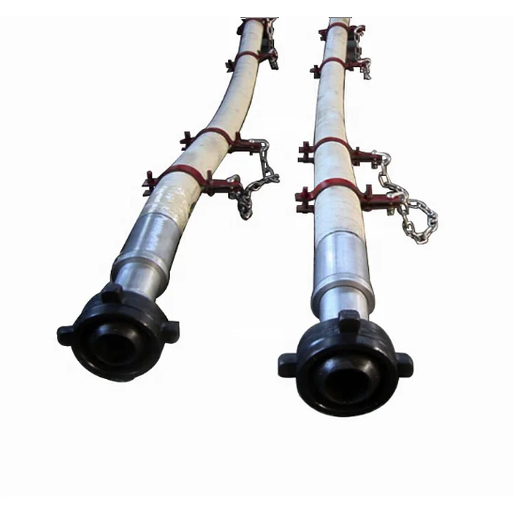
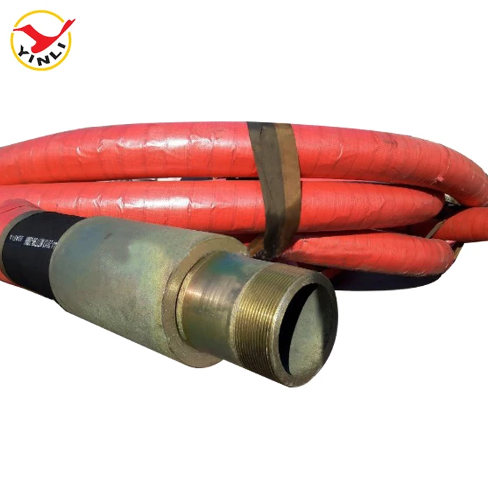
Flexible drilling rubber hoses play an important role in petroleum extraction. They should suffer high operating pressure, extreme operating temperature, abrasion and other inferior elements. Our special compounded synthetic rubber has been proven an effective and economical way to reject these problems. All our oilfield drill hoses are manufactured as API 7K or other related specifications.
Steel cable reinforcement loads most working pressure up to 15,000psi. The wires are usually zinc-plating or copper platting to improve steel wire resistant against rust and corrosion. Due to the thick reinforcement, the hoses should be handled or stored in correct way to avoid kicking or crushing. They will substantially decrease their rated operating pressure.
Rotary hose, Kelly hose, cement hose, mud hose, jumper hose and vibrator hose and choke & kill hoses are the most popular oilfield rubber hoses. They convey high-pressure drilling fluid from one place to another. Many end fittings are provided to satisfy different applications. Most end fittings are made according to API standards. Special order is also available.

In an effort to prevent kinking, binding or snagging of kelly spinner hoses during the raising and lowering of said hoses together with a rotary hose in oil drilling rigs, it is known to tape the kelly spinner hoses to the rotary hose which provides the drilling fluid. There is a serious defect in this arrangement since the kelly spinner hoses and the rotary hose are used independently in the sense that they are under different pressures at different times. Thus, for example, the kelly spinner hoses will not be pressurized with air when the rotary hose is pressurized with the drilling fluid. Since the pressurization of the rotary hose is typically in the range of from four thousand to five thousand psi, the hose is substantially elongated typically from about six to ten inches. This results in substantial straining of the kelly hoses. By the same token the kelly hoses when they are pressurized, are strained due to the fact they are prevented from moving relative to the rotary hose. Further, these strains have a tendency to rupture the tape leaving the kelly spinner hoses free to move independently which is a serious hazard for rig personnel since, if one of these hoses ruptures or separates from the fittings attached to the kelly swivel it will whip violently incident to the exhausting of the high pressure air through the rupture or the freed end of the hose. All of these problems have been solved by this invention by providing guides for the kelly hoses which attach to the rotary hose and permit the kelly hose and the rotary hose to move freely axially relative to each other while preventing kinking, binding and snagging while the hoses are raised and lowered. In addition, the invention facilitates the installing and disconnecting the kelly spinner hoses. The life expectancy of the kelly spinner hoses is increased, reducing down time.
The invention is a safety guide for kelly spinner hoses in drilling rigs and a plurality of said safety guides in combination with kelly hoses and a rotary hose. Each safety guide comprises a pair of opposed rings, each adapted to receive and guide a kelly spinner hose, and a device for securing the rings to a rotary hose substantially in a plane perpendicular to the axis of the rotary hose. Advantageously, each ring has a rigid integral loop member and the securing device comprises a flexible band passing through said loop members. It is preferred to secure the band to the rotary hose with a buckle. In the combination, a plurality of the safety guides are spaced along the length of the rotary hose, preferably substantially equidistant.
FIG. 3 is an elevational view showing a guide in accordance with the invention in association with the kelly spinner hoses and the rotary hose of the rig of FIG. 1;
Referring to FIG. 1, an oil drilling rig 2 has a derrick 4 having a hoist 6 provided with a lifting hook 8 which is adapted to engage a ring 10 (FIG. 2) attached to a swivel fitting 12 which in turn is connected to a kelly indicated at 16 adapted to connect with a rotary table 18 (FIG. 1). A kelly spinner 20 rotates kelly 16 and is supported by a turn buckle 22 connected to swivel fitting 12.
A rotary hose 26 is connected by a fitting indicated at 28 (FIG. 2) to swivel fitting 12. Rotary hose 26 is connected to a stand pipe 30 which is adapted to deliver a drilling fluid as indicated at 32 (FIG. 1). Kelly spinner hoses 40 and 42 are connected to Kelly spinner 20 and are respectively connected to their delivery pipes 44 and 46 as indicated at 48 and 50 (separated for clarity in FIG. 1, but actually close to fitting 32).
Kelly spinner hoses 40 and 42 are each guided by a plurality of guides 60 in accordance with the invention which are substantially equally spaced along the length of rotary hose 26.
As best seen in FIG. 4, each guide 60 has a pair of opposed guide rings 62 and 64 through which hoses 40 and 42 pass respectively. Guide ring 62 has an integral member loop member 66 which runs substantially perpendicular to a plane through ring 62 and has a relatively narrow opening 68 (FIG. 3). Likewise, guide ring 64 has an integral loop member 72 running substantially perpendicular to the plane of ring 64 and having a relatively narrow opening 74.
A band 78 passes through openings 68 and 74 and around rotary hose 26 to which it is tightly secured by buckle 80. Buckle 80 has a flat plate 82 to which is secured a loop 84 (FIG. 5) and outwardly and downwardly extending opposed fingers 86, 86. The inner end 90 of band 78 passes between plate 82 and loop 84 and between back plate 82 and fingers 86, 86 and is bent back on itself inside of plate 82. Band 78 is then run around rotary hose 26 twice passing through loop members 66 and 72 and between plate 82 and both loop 84 and fingers 86 twice to form two loops indicated at 96 and 98 in FIG. 4 and then outer end 92 is turned back on itself over loop 84 and passed inside of fingers 86, 86 thus securing the rings 62 and 64 to rotary hose 26 (FIGS. 4 and 5).
The guides 60 are substantially equally spaced along hose 26 advantageously at a distance of from about 96 to about 144 inches. It will be seen that since the kelly spinner hoses 40 and 42 are loosely received in guide rings 62 and 64 each of the hoses 40, 42 and 26 can move freely axially relative to each other. Should one of the hoses 40 or 42 become detached from the kelly spinner it will be prevented from dangerous whipping. While a variety of materials may be used to make the guides 60, it is preferred to employ stainless steel for all the parts. The guide rings 62 and 64 are conveniently welded to loop members 66 and 72 as indicated at 100 and 102 respectively in FIGS. 3 and 4.

The main advantage of a kelly hose is that it helps you move water from one point to another without much struggle. Hose pipes are also versatile and can be used for various activities in your home or at your workplace. Moreover, rubber horse pipes are durable since rubber is a strong material. This means that you won’t need to replace it often. Additionally, rubber hoses are less prone to cuts and abrasions. Another advantage of this hose pipe is that it absorbs shocks and vibrations. Also, there is no need for specialized bending or brazing since it can bend easily. Lastly, it reduces pressure surges and lubricates itself.
When buying a kelly hose, there are several factors that you need to consider, including length, couplings, thickness, and price. The length of the kelly hose is an important factor to consider. If you are taking the water to the furthest corner of your compound, consider getting a longer pipe for convenience. Also, if you are watering a large garden, a longer pipe will serve you better. Couplings or horse pipe fittings are also another important consideration. These are the accessories that help you connect your pipe to the water source. They can either be made from brass or plastic. Some people prefer plastic couplings since they are lightweight, but they can break easily. Brass fittings are heavier but long-lasting. Lastly, consider the thickness of the pipe. This refers to the number of layers used to make the kelly hose. Thickness determines the weight of the pipe and ease of bending.
For a wholesale kelly hose, visit Alibaba.com. This online shopping platform offers a wide range of rubber hoses that suits your needs. Visit the website at any time and place your order.
A kelly drive is a type of well drilling device on an oil or gas drilling rig that employs a section of pipe with a polygonal (three-, four-, six-, or eight-sided) or splined outer surface, which passes through the matching polygonal or splined kelly (mating) bushing and rotary table. This bushing is rotated via the rotary table and thus the pipe and the attached drill string turn while the polygonal pipe is free to slide vertically in the bushing as the bit digs the well deeper. When drilling, the drill bit is attached at the end of the drill string and thus the kelly drive provides the means to turn the bit (assuming that a downhole motor is not being used).
The kelly is the polygonal tubing and the kelly bushing is the mechanical device that turns the kelly when rotated by the rotary table. Together they are referred to as a kelly drive. The upper end of the kelly is screwed into the swivel, using a left-hand thread to preclude loosening from the right-hand torque applied below. The kelly typically is about 10 ft (3 m) longer than the drill pipe segments, thus leaving a portion of newly drilled hole open below the bit after a new length of pipe has been added ("making a connection") and the drill string has been lowered until the kelly bushing engages again in the rotary table.
The kelly hose is the flexible, high-pressure hose connected from the standpipe to a gooseneck pipe on a swivel above the kelly and allows the free vertical movement of the kelly while facilitating the flow of the drilling fluid down the drill string. It generally is of steel-reinforced rubber construction but also assemblies of Chiksan steel pipe and swivels are used.
The kelly is below the swivel. It is a pipe with either four or six flat sides. A rotary bushing fits around the flat sides to provide the torque needed to turn the kelly and the drill string. Rollers in the bushing permit the kelly free movement vertically while rotating. Since kelly threads would be difficult to replace, normally the lower end of the kelly has saver sub — or a short piece of pipe — that can be refurbished more cheaply than the kelly. Usually, a ball valve, called the lower kelly cock, is positioned between the kelly and the kelly saver sub. This valve is used for well control if the surface pressure becomes too high for the rotary hose or surface conditions.
According to the ″Dictionary of Petroleum Exploration, Drilling and Production″, ″[The] kelly was named after Michael J. (King) Kelly, a Chicago baseball player (1880-1887) who was known for his base running and long slides.″
n: a record made each day of the operations on a working drilling rig and, traditionally, phoned, faxed, emailed, or radioed in to the office of the drilling company and possibly the operator every morning.
(pronounced "tower") n: in areas where three eight-hour tours are worked, the shift of duty on a drilling rig that starts at or about daylight. Compare evening tour, morning (graveyard) tour.
(pronounced "tower") n: in areas where two 12-hour tours are worked, a period of 12 hours, usually during daylight, worked by a drilling or workover crew when equipment is being run around the clock.
n: the mass or weight of a substance per unit volume. For instance, the density of a drilling mud may be 10 pounds per gallon, 74.8 pounds/cubic foot, or 1,198.2 kilograms/cubic meter. Specific gravity, relative density, and API gravity are other units of density.
n: a large load-bearing structure, usually of bolted construction. In drilling, the standard derrick has four legs standing at the corners of the substructure and reaching to the crown block. The substructure is an assembly of heavy beams used to elevate the derrick and provide space to install blowout preventers, casingheads, and so forth.
n: the crew member who handles the upper end of the drill string as it is being hoisted out of or lowered into the hole. On a drilling rig, he or she may be responsible for the circulating machinery and the conditioning of the drilling or workover fluid.
n: a high-compression, internal-combustion engine used extensively for powering drilling rigs. In a diesel engine, air is drawn into the cylinders and compressed to very high pressures; ignition occurs as fuel is injected into the compressed and heated air. Combustion takes place within the cylinder above the piston, and expansion of the combustion products imparts power to the piston.
n: 1. intentional deviation of a wellbore from the vertical. Although wellbores are normally drilled vertically, it is sometimes necessary or advantageous to drill at an angle from the vertical. Controlled directional drilling makes it possible to reach subsurface areas laterally remote from the point where the bit enters the earth.
n: in well cementing, the fluid, usually drilling mud or salt water, that is pumped into the well after the cement is pumped into it to force the cement out of the casing and into the annulus.
n: a drilling tool made up in the drill string directly above the bit. It causes the bit to turn while the drill string remains fixed. It is used most often as a deflection tool in directional drilling, where it is made up between the bit and a bent sub (or, sometimes, the housing of the motor itself is bent). Two principal types of downhole motor are the positive-displacement motor and the downhole turbine motor.
n: the employee normally in charge of a specific (tour) drilling or workover crew. The driller’s main duty is operation of the drilling and hoisting equipment, but this person may also be responsible for downhole condition of the well, operation of downhole tools, and pipe measurements.
n: an agreement made between a drilling company and an operating company to drill a well. It generally sets forth the obligation of each party, compensation, identification, method of drilling, depth to be drilled, and so on.
n: an internal-combustion engine used to power a drilling rig. These engines are used on a rotary rig and are usually fueled by diesel fuel, although liquefied petroleum gas, natural gas, and, very rarely, gasoline can also be used.
n: all members in the assembly used for rotary drilling from the swivel to the bit, including the kelly, the drill pipe and tool joints, the drill collars, the stabilizers, and various specialty items. Compare drill string.
n: a method of formation testing. The basic drill stem test tool consists of a packer or packers, valves or ports that may be opened and closed from the surface, and two or more pressure-recording devices. The tool is lowered on the drill string to the zone to be tested. The packer or packers are set to isolate the zone from the drilling fluid column.
n: the column, or string, of drill pipe with attached tool joints that transmits fluid and rotational power from the kelly to the drill collars and the bit. Often, the term is loosely applied to include both drill pipe and drill collars.

AUTHORIZATION FOR EXPENDITURE (AFE)A document used to estimate the cost of drilling a well or installing major equipment facilities in an oil field. The AFE is submitted to management and/or industry partners in the activity for their authorization and approval of the expenditure. The AFE is a budgetary device; when the project is complete, the operator collects invoices of actual work done and compares it to the AFE, should the project come in under budget, he refunds the balance. If the project has cost overruns, the operator submits additional invoices to the participants.
DEVELOPMENT DRILLING– A development well is generally a well drilled as an additional well to the same oil and gas reservoir as other producing wells and not more than one location away from a producing well.
DRILLING MUD –A special mixture of clay, water, and chemical additives pumped down hole through the drill pipe and drill bit. The mud cools the rapidly rotating drill bit; lubricates the drill pipe as it turns in the well bore; carries rock cuttings to the surface; and serves as plaster to prevent the wall of the bore hole from crumbling or collapsing. Drilling mud also provides the weight or hydrostatic head to prevent extraneous fluids to entering the well bore and to control down-hole pressures that might be encountered.
DRY-HOLE COST –The cost of drilling the well; also known asDRILLING COST. Completion costs are in addition to drilling costs but only come due if the well locates producible oil or gas.
FARM OUT AGREEMENT– A form of agreement between oil operators whereby the owner of a lease who is not interested in drilling at the time agrees to assign the lease or a portion of it to another operator who wishes to drill the acreage. The seller may or may not retain an interest (Royalty or production payment) in the production.
FLANGE-UP– Oil-field slang meaning to finish the job. Derived from work with pipe having flanges (rims) on the ends; this pipe is bolted together at those flanges; the pipe can carry liquids once it is “Flanged Up.”
GAS-CUT MUD– Drilling mud aerated or charged with gas from formations down hole. The gas forms bubbles in the drilling fluid. Gas-cut mud may indicate commercial quantities of gas present in the formation.
GAS KICK– Pressure from down hole in excess of that exerted by the weight of the drilling mud, causing loss of circulation. If the gas pressure is not controlled by increasing the mud weight, a kick can violently expel the column of drilling mud resulting in aBlow-out.
INFILL DRILLING –Wells drilled to fill in between established producing wells on a lease to increase production from the lease. SeeDevelopment Drilling.
INTANGIBLE DRILLING COSTS –Expenditures made by an operator for labor, fuel, repairs, hauling and supplies used in drilling and completing a well for production. Intangible drilling costs include also the construction of derricks, tanks, pipelines on the lease, buildings, and preparation of the drill site but does not include the cost of materials or equipment. A rule of thumb is: do the items for which expenditure were made have any salvage value? If not, they qualify under the tax laws as intangible drilling costs.
INTERMEDIATE STRING– SeeCasing. There may be several strings of casing in a well, one inside another. The first casing put in a well is called Surface Pipe which is cemented into place and serves to shut out and protect shallow water formations and also as a foundation or anchor for all subsequent drilling activity. Extremely deep wells will often have an “intermediate string” cemented in place to protect and preserve the well bore as the remaining hole is drilled and completed.
JACK–KNIFE RIG– A mast-type derrick whose supporting legs are hinged at the base. When the rig is to be moved, it is lowered or laid down intact and transported by truck.
JOINT– A length of pipe, casing, or tubing usually from 20 to 30 feet long. On a drilling rig, drill pipe and tubing are lowered into the hole the first time one joint at a time. When pulled from the hole and stacked in the rig, they are usually pulled two, three, or four at a time. These multiple-joint sections are calledStands.
KELLY– The first and sturdiest joint of the drill column; a thick-walled, hollow steel forging with two flat sides and two rounded sides. When fitted into the square hole in the rotary table will rotate the kelly joint and thence the drill column and drill bit. Attached to the top of the kelly is the swivel andmud hose.
KELLY HOSE or MUD HOSE –This is a flexible, steel-reinforced, rubber hose connecting the mud pump with the swivel and kelly joint on the drilling rig. Mud is pumped through the mud hose to the swivel and down through the kelly joint and drill pipe to the drill bit at the bottom of the hole.
LOSS OF CIRCULATION– A condition that exists when drilling mud pumped into the well through the drill pipe does not return to the surface. This serious condition results from the mud being lost in porous formations, a crevice or cavern penetrated by the drill bit.
LOST CIRCULATION MATERIAL –Material that is added to the drilling mud when circulation is lost to assist in plugging the breached area of the well bore.
MUD –A special mixture of clay, water, and chemical additives pumped down hole through the drill pipe and drill bit. The mud cools the rapidly rotating drill bit; lubricates the drill pipe as it turns in the well bore; carries rock cuttings to the surface; and serves as plaster to prevent the wall of the bore hole from crumbling or collapsing. Drilling mud also provides the weight or hydrostatic head to prevent extraneous fluids to entering the well bore and to control down-hole pressures that might be encountered. SeeDrilling Mud and Blow Out.
MUDLOG –A progressive analysis of the well-bore cuttings washed up from the bore hole by the drilling mud. Rock chips are retrieved and examined by the geologist. Modern drilling operations include an electronic evaluation of the mud itself that indicates the presence of hydrocarbons in the mud along with the analysis of the well-bore cuttings.
MUD PITS –SeeRESERVE PITS. Excavations near the rig into which drilling mud is circulated. Mud pumps withdraw the mud from one end of the pit as the circulated mud, bearing rock chips from the bore hole, flows in at the other end. As the mud moves toward the suction line, the cuttings drop out leaving “clean” mud ready for another drip down the well bore.
ONE-THIRD FOR A QUARTER– A term used by independent oil operators who are selling interests in a well they propose to drill. An industry partner who agrees to the one-third for a quarter deal will pay one-third of the cost of the well to some point and receive one-fourth of the well’s net production. When the operator sells three of these one-third for a quarter interests, his industry partners will have paid the cost of drilling the well to casing point.
OPERATOR– A person or entity engaged in the business of exercising direct responsibility and supervision over drilling, completion, operation, maintenance, and production from an oil/gas well.
PAYOUT– The recovery from production of the costs of drilling, completing and equipping a well. Sometimes included in in the costs is a pro-rata share of lease costs.
RAT HOLE –A slanted hole drilled near the well’s bore hole to hold theKellyjoint when not in use. The kelly is unscrewed from the drill string and lowered into the rat hole as a pistol into a scabbard.
RESERVE PIT –SeeMud Pits. An excavation connected to the working mud pits of a drilling well to hold excess or reserve drilling mud; a standby pit containing already-mixed drilling mud for use in an emergency when extra mud is needed.
ROYALTY a.k.a. ROYALTY INTEREST (R.I.)A share of the minerals (oil and gas) produced from a property by the owner of the property. Originally, the right of the king to receive a percentage of the minerals taken from the mines of his realm. (Silver, gold, salt, copper, etc) Entitles the owner to a share of gross proceeds which is free of expense of drilling, completion and production, but having no control over field activities.
SCOUT TICKET– a standard form of information about activities on a drilling location or well. The information includes dates, well’s depth, formations encountered, well logs and tests run. Completion information is briefly described as is the fate of the well, whether put in production or plugged.
SPUD– To start the actual drilling of a well. The first section of the hole is drilled with a large-diameter spudding bit down several hundred feet to accommodate the surface pipe which may be 8 to 20 inches in diameter, depending upon the depth to which the well will ultimately be drilled. The surface pipe is cemented into this hole to protect the surface formations which might contain potable water.
STEP-OUT WELL – a.k.a. Offset Well– A well drilled adjacent to a proven well but located in an unproven area; a well located a “step out” from proven territory in an effort to determine the boundaries of a producing formation. SeeDevelopment Drilling.
TURNKEY CONTRACT– A contract to drill, complete and equip an oil or gas well for a set, predetermined price. The turnkey format is designed to limit the liability of an industry partner to the amount of their capital contribution for drilling and completion.
WORKING INTEREST (W.I.)– The operating interest entitling the holder, at his or its expense, to conduct drilling and production operations on the property and to receive the net revenues from such operations.

RC, or reverse circulation, drilling is a tried and true drilling method in certain circumstances. Drillers usually use it on large-diameter holes because it is faster and easier to clean the hole. The fluid and cuttings flow up the drill pipe and down the annulus. In softer formations, this causes less washout and makes sampling faster and more accurate because cuttings are not contaminated by sloughing formation off the hole walls. They also come up the drill pipe very fast, giving an accurate formation log.
There are two general methods of RC. First is flooded reverse, where fluid is introduced through a flow ditch to the hole to keep it full. This works well in fairly unconsolidated formations that need some hydrostatic head. The trick here is to have enough water supply to keep up with any losses to the formation. In extreme loss situations, high-viscosity mud can be introduced to help stabilize the hole, but it might take A LOT of mud. Usually in these situations, we drill with direct circulation until we can get enough casing set to get into more stable formations. This RC method can be used with either a large centrifugal pump to maintain flow, or air lift. A centrifugal pump system will need a “rock catcher” between the Kelly hose and the pump to catch cobbles big enough to damage the pump.
We once drilled a well in Orlando, Fla., with this method. The well produced 400 or 500 gallons a minute of water we had to get rid of. The disposal requirements were for very low turbidity, so we built a 4,000-gallon sand filter that did very well. Once filtered, and since the water was potable from the producing formation, we had no problem pumping it to a nearby pond. We pumped through 4-inch lines and, where they crossed the road, we rented one of those heavy, plastic ramp deals that fire departments use, to let traffic pass. The only funny thing was a kid showed up on location one day all mad. It seems he had one of those lowrider trucks with about 1 inch of ground clearance. Got high-centered on the crossover. We took the backhoe down there and got him off. I told him he needed to fix his suspension. He didn’t think it was funny.
One important factor in RC drilling is drill pipe size. Generally, the bigger the better. I find that 4½- or 5½-inch works well. I have done it with 2 7⁄8-inch, but plugging is a problem and penetration is very slow. The airline inside is usually 1 inch. I use pvc pipe. The length of the airline depends on the depth to the static water level. Usually, at least 50 percent submergence, or more, is good. The deeper the air line, the better. It’ll work, but you might run into compressor issues if you are very deep. I’ve done well with 500 feet of air line on a 3,000-foot hole.
One of the key problems in RC drilling is bit or drill pipe plugging. Large holes, and large bits to make a lot of those holes, make a lot of cuttings. Those cuttings can only be transported to the surface so fast. The key is proper air flow and instrumentation. Not enough volume of air, and the cuttings won’t keep up. Too much air, and there isn’t enough room for the cuttings with all that air in the pipe. In 4½-inch drill pipe, a 185 cfm compressor has worked well for me. I can throttle it just a little to find the “sweet spot.” A good, accurate air gauge is critical. When you get on bottom and start the air, it will settle down to a steady number, and you are ready to put the bit on bottom. Keep your eye on the gauge. Any drop in air pressure indicates bit plugging. At this point, quit drilling, pick up and vigorously work the pipe. This should dislodge the plug. If not, you may be able to pump into it to open the pipe. If not, you’re are going to have to come out of the hole to clear the plug. Not fun. Embarrassing. Prevention is the better plan. I usually pick up at a 5-pound pressure drop.
The last thing that comes to mind about RC drilling is development. In our area, we produce from limestone. With RC, you are constantly pulling formation water into the hole. This means no cuttings that have to be developed out later. We just set the test pump, and let ’er rip. Often, turbidity clears in minutes. Sampling is also faster and more accurate. For some reason, geologists like that.

This feature allows you to quickly disconnect the mast when working inside buildings, underneath bridges or in other low overhead drilling locations. Since the mast is completely separated from the upright, it doesn’t interfere with other drill functions such as the in-out slide base. With the mast in the horizontal position, you simply clamp it to its storage rack and extend the drill’s in-out slide base. This pulls the sockets on the upright drill frame away from the large tapered pins on the mast.
This unique system is especially effective for drilling underneath ponds, storage tanks, or other structures. When used with our patented continuous sample tube system, you can even take soil samples while drilling angle holes. The angle drilling system will also allow you to drill vertically with the carrier positioned on an uphill slope. That can eliminate the time-consuming job of leveling the rig. And, since the kelly drive is always coupled to the right angle drive box, you can raise and lower the mast with the drivetrain already connected and ready to go.
CPT controls allow you to easily switch from typical geotechnical drilling and sampling procedures to pushing a cone. A dedicated hydraulic circuit including detented CPT control lever, hydraulic down feed pressure and CPT feed rate controls provide precise pressure and penetration adjustments required to meet ASTM standards. A separate CPT system hydraulic pressure gauge is provided as well. Anchor points are installed below the drill feed frame so that maximum available pressure can be applied to the CPT tools. A 12-volt power source can be provided at the drill control panel to accommodate electronic devices associated with CPT procedures. Mounting for depth transducers or other related equipment can also be provided.


 8613371530291