
kelly hose standpipe free sample

Flexible drilling rubber hoses play an important role in petroleum extraction. They should suffer high operating pressure, extreme operating temperature, abrasion and other inferior elements. Our special compounded synthetic rubber has been proven an effective and economical way to reject these problems. All our oilfield drill hoses are manufactured as API 7K or other related specifications.
Steel cable reinforcement loads most working pressure up to 15,000psi. The wires are usually zinc-plating or copper platting to improve steel wire resistant against rust and corrosion. Due to the thick reinforcement, the hoses should be handled or stored in correct way to avoid kicking or crushing. They will substantially decrease their rated operating pressure.
Rotary hose, Kelly hose, cement hose, mud hose, jumper hose and vibrator hose and choke & kill hoses are the most popular oilfield rubber hoses. They convey high-pressure drilling fluid from one place to another. Many end fittings are provided to satisfy different applications. Most end fittings are made according to API standards. Special order is also available.

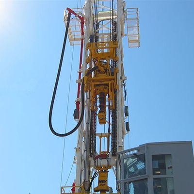
Kelly hose is used to connect the standpipe to the swivel. It allows the drill string to be raised and lowered while the drill fluid is pumped through it. Kelly line usually contains two layers of plated steel cables to reach 5000 psi operating pressure. Inside tube is made of special NBR to improve abrasion and corrosion capability. Rubber cover is compatible with the ozone, sunlight and oils for a long time. It is supplied with multiple end fittings – API flanges, threads, butt-welded union and other as specified.

In an effort to prevent kinking, binding or snagging of kelly spinner hoses during the raising and lowering of said hoses together with a rotary hose in oil drilling rigs, it is known to tape the kelly spinner hoses to the rotary hose which provides the drilling fluid. There is a serious defect in this arrangement since the kelly spinner hoses and the rotary hose are used independently in the sense that they are under different pressures at different times. Thus, for example, the kelly spinner hoses will not be pressurized with air when the rotary hose is pressurized with the drilling fluid. Since the pressurization of the rotary hose is typically in the range of from four thousand to five thousand psi, the hose is substantially elongated typically from about six to ten inches. This results in substantial straining of the kelly hoses. By the same token the kelly hoses when they are pressurized, are strained due to the fact they are prevented from moving relative to the rotary hose. Further, these strains have a tendency to rupture the tape leaving the kelly spinner hoses free to move independently which is a serious hazard for rig personnel since, if one of these hoses ruptures or separates from the fittings attached to the kelly swivel it will whip violently incident to the exhausting of the high pressure air through the rupture or the freed end of the hose. All of these problems have been solved by this invention by providing guides for the kelly hoses which attach to the rotary hose and permit the kelly hose and the rotary hose to move freely axially relative to each other while preventing kinking, binding and snagging while the hoses are raised and lowered. In addition, the invention facilitates the installing and disconnecting the kelly spinner hoses. The life expectancy of the kelly spinner hoses is increased, reducing down time.
The invention is a safety guide for kelly spinner hoses in drilling rigs and a plurality of said safety guides in combination with kelly hoses and a rotary hose. Each safety guide comprises a pair of opposed rings, each adapted to receive and guide a kelly spinner hose, and a device for securing the rings to a rotary hose substantially in a plane perpendicular to the axis of the rotary hose. Advantageously, each ring has a rigid integral loop member and the securing device comprises a flexible band passing through said loop members. It is preferred to secure the band to the rotary hose with a buckle. In the combination, a plurality of the safety guides are spaced along the length of the rotary hose, preferably substantially equidistant.
FIG. 3 is an elevational view showing a guide in accordance with the invention in association with the kelly spinner hoses and the rotary hose of the rig of FIG. 1;
Referring to FIG. 1, an oil drilling rig 2 has a derrick 4 having a hoist 6 provided with a lifting hook 8 which is adapted to engage a ring 10 (FIG. 2) attached to a swivel fitting 12 which in turn is connected to a kelly indicated at 16 adapted to connect with a rotary table 18 (FIG. 1). A kelly spinner 20 rotates kelly 16 and is supported by a turn buckle 22 connected to swivel fitting 12.
A rotary hose 26 is connected by a fitting indicated at 28 (FIG. 2) to swivel fitting 12. Rotary hose 26 is connected to a stand pipe 30 which is adapted to deliver a drilling fluid as indicated at 32 (FIG. 1). Kelly spinner hoses 40 and 42 are connected to Kelly spinner 20 and are respectively connected to their delivery pipes 44 and 46 as indicated at 48 and 50 (separated for clarity in FIG. 1, but actually close to fitting 32).
Kelly spinner hoses 40 and 42 are each guided by a plurality of guides 60 in accordance with the invention which are substantially equally spaced along the length of rotary hose 26.
As best seen in FIG. 4, each guide 60 has a pair of opposed guide rings 62 and 64 through which hoses 40 and 42 pass respectively. Guide ring 62 has an integral member loop member 66 which runs substantially perpendicular to a plane through ring 62 and has a relatively narrow opening 68 (FIG. 3). Likewise, guide ring 64 has an integral loop member 72 running substantially perpendicular to the plane of ring 64 and having a relatively narrow opening 74.
A band 78 passes through openings 68 and 74 and around rotary hose 26 to which it is tightly secured by buckle 80. Buckle 80 has a flat plate 82 to which is secured a loop 84 (FIG. 5) and outwardly and downwardly extending opposed fingers 86, 86. The inner end 90 of band 78 passes between plate 82 and loop 84 and between back plate 82 and fingers 86, 86 and is bent back on itself inside of plate 82. Band 78 is then run around rotary hose 26 twice passing through loop members 66 and 72 and between plate 82 and both loop 84 and fingers 86 twice to form two loops indicated at 96 and 98 in FIG. 4 and then outer end 92 is turned back on itself over loop 84 and passed inside of fingers 86, 86 thus securing the rings 62 and 64 to rotary hose 26 (FIGS. 4 and 5).
The guides 60 are substantially equally spaced along hose 26 advantageously at a distance of from about 96 to about 144 inches. It will be seen that since the kelly spinner hoses 40 and 42 are loosely received in guide rings 62 and 64 each of the hoses 40, 42 and 26 can move freely axially relative to each other. Should one of the hoses 40 or 42 become detached from the kelly spinner it will be prevented from dangerous whipping. While a variety of materials may be used to make the guides 60, it is preferred to employ stainless steel for all the parts. The guide rings 62 and 64 are conveniently welded to loop members 66 and 72 as indicated at 100 and 102 respectively in FIGS. 3 and 4.

12.2.1 Small hose connections [11⁄2 in. (38 mm)] shall be provided where required by the authority having jurisdiction in accordance with 8.17.5 for first-aid fire-fighting and overhaul operations.
12.2.2 Small hose connections shall not be required for the protection of Class I, II, III, and IV commodities stored 12 ft (3.7 m) or less in height.
8.17.5.1.4* Hose connections used for fire purposes only shall be permitted to be connected to wet pipe sprinkler systems only, subject to the following restrictions:
(2) The requirements of 8.17.5.1.4(1) shall not apply to hydraulically designed loops and grids, where the minimum size pipe between the hose connection’s supply pipe and the source shall be permitted to be 2 in. (50 mm).
(3) For piping serving a single hose connection, pipe shall be a minimum of 1 in. (25 mm) for horizontal runs up to 20 ft (6.1 m), a minimum of 11⁄4 in. (32 mm) for the entire run for runs between 20 ft and 80 ft (6.1 m and 24 m), and a minimum of 11⁄2 in. (40 mm) for the entire run for runs greater than 80 ft (24 m). For piping serving multiple hose connections, runs shall be a minimum of 11⁄2 in. (40 mm) throughout.
(5) Where the residual pressure at a 11⁄2 in. (40 mm) outlet on a hose connection exceeds 100 psi (7 bar), an approved pressure-regulating device shall be provided to limit the residual pressure at the outlet to 100 psi (7 bar).
(6) Where the static pressure at a 11⁄2 in. (40 mm) hose connection exceeds 175 psi (12 bar), an approved pressure regulating device shall be provided to limit static and residual pressures at the outlet to 100 psi (7 bar).
20.15.8.3.1 When any portion of the high-piled combustible storage area is greater than 200 ft (61 m) from a fire department access door, Class I standpipe outlets connected to a system sized to deliver 250 gpm (946.4 L/min) at the most hydraulically remote outlet shall be provided in accordance with 20.15.8.3. 20.15.8.3.2 The outlet shall be permitted to be supplied from the sprinkler system and shall be hydraulically calculated.
I have designed many speculative shell warehouses where class I hose connections were required due to the width of the building, but small hose connections were not required by the AHJ until a tenant leased the building (or portion of) and maintained areas intended for storage.

A kelly drive is a type of well drilling device on an oil or gas drilling rig that employs a section of pipe with a polygonal (three-, four-, six-, or eight-sided) or splined outer surface, which passes through the matching polygonal or splined kelly (mating) bushing and rotary table. This bushing is rotated via the rotary table and thus the pipe and the attached drill string turn while the polygonal pipe is free to slide vertically in the bushing as the bit digs the well deeper. When drilling, the drill bit is attached at the end of the drill string and thus the kelly drive provides the means to turn the bit (assuming that a downhole motor is not being used).
The kelly is the polygonal tubing and the kelly bushing is the mechanical device that turns the kelly when rotated by the rotary table. Together they are referred to as a kelly drive. The upper end of the kelly is screwed into the swivel, using a left-hand thread to preclude loosening from the right-hand torque applied below. The kelly typically is about 10 ft (3 m) longer than the drill pipe segments, thus leaving a portion of newly drilled hole open below the bit after a new length of pipe has been added ("making a connection") and the drill string has been lowered until the kelly bushing engages again in the rotary table.
The kelly hose is the flexible, high-pressure hose connected from the standpipe to a gooseneck pipe on a swivel above the kelly and allows the free vertical movement of the kelly while facilitating the flow of the drilling fluid down the drill string. It generally is of steel-reinforced rubber construction but also assemblies of Chiksan steel pipe and swivels are used.
The kelly is below the swivel. It is a pipe with either four or six flat sides. A rotary bushing fits around the flat sides to provide the torque needed to turn the kelly and the drill string. Rollers in the bushing permit the kelly free movement vertically while rotating. Since kelly threads would be difficult to replace, normally the lower end of the kelly has saver sub — or a short piece of pipe — that can be refurbished more cheaply than the kelly. Usually, a ball valve, called the lower kelly cock, is positioned between the kelly and the kelly saver sub. This valve is used for well control if the surface pressure becomes too high for the rotary hose or surface conditions.
According to the ″Dictionary of Petroleum Exploration, Drilling and Production″, ″[The] kelly was named after Michael J. (King) Kelly, a Chicago baseball player (1880-1887) who was known for his base running and long slides.″
A device fitted to the rotary table through which the kelly passes. It is the means by which the torque of the rotary table is transmitted to the kelly and to the drill stem. Also called the drive bushing.†
A hole in the rig floor 30 to 35 feet deep, lined with casing that projects above the floor. The kelly is placed in the rathole when hoisting operations are in progress.†
The hose on a rotary drilling rig that conducts the drilling fluid from the mud pump and standpipe to the swivel and kelly; also called the mud hose or the kelly hose.†
A vertical pipe rising along the side of the derrick or mast. It joins the discharge line leading from the mud pump to the rotary hose and through which mud is pumped going into the hole.†
A rotary tool that is hung from the rotary hook and traveling block to suspend and permit free rotation of the drill stem. It also provides a connection for the rotary hose and a passageway for the flow of drilling fluid into the drill stem.†
The top drive rotates the drill string end bit without the use of a kelly and rotary table. The top drive is operated from a control console on the rig floor.†

In an ideal drilling environment surface pressure will remain steady and all pressure increases, and decreases will be gradual. This way, when the pulser valve closes(pulses), it’s easily detectable on surface by computers. Unfortunately drilling environments are rarely perfect and there are many things that can emulate a pulse thus causing poor or inaccurate data delivery to surface. The unfortunate circumstance of this means drilling operations must come to halt until data can once again be decoded on surface. This pause in the drilling process is commonly referred to at NPT or non-productive time. For those of you unfamiliar these concepts, I’ll explain some of the basics.
Depending on if the drilling fluid is being circulated in closed or open loop, it will be drawn from a tank or a plastic lined reservoir by a series(or one) mud pumps and channeled into the stand pipe, which runs up the derrick to the Kelly-hose, through the saver sub and down the drill-pipe(drill-string). Through the filter screen past an agitator or exciter, around the MWD tool, through a mud motor and out of the nozzles in the bit. At this point the fluid begins it’s journey back to the drilling rig through the annulus, past the BOP then out of the flow line and either over the shale shakers and/or back in the fluid reservoir.
Suction screens on intake hoses will occasionally be too large, fail or become unfastened thus allowing large debris in the mud system. Depending on the size of debris and a little bit of luck it can end up in an area that will inhibit flow, circumstantially resulting in a sudden fluctuation of pressure.
Over time mud pump components wear to the point failure. Pump pistons(swabs), liners, valves and valve seats are all necessary components for generating stable pressure. These are the moving parts on the fluid side of the pump and the most frequent point of failure. Another possible culprit but less common is an inadequately charged pulsation dampener. Deteriorating rubber hoses anywhere in the fluid path, from the mud pump to the saver sub, such as a kelly-hose, can cause an occasional pressure oscillation.


 8613371530291