
mechanical seal diagram factory

A mechanical seal is simply a method of containing fluid within a vessel (typically pumps, mixers, etc.) where a rotating shaft passes through a stationary housing or occasionally, where the housing rotates around the shaft.
When sealing a centrifugal pump, the challenge is to allow a rotating shaft to enter the ‘wet’ area of the pump, without allowing large volumes of pressurized fluid to escape.
To address this challenge there needs to be a seal between the shaft and the pump housing that can contain the pressure of the process being pumped and withstand the friction caused by the shaft rotating.
Before examining how mechanical seals function it is important to understand other methods of forming this seal. One such method still widely used is Gland Packing.
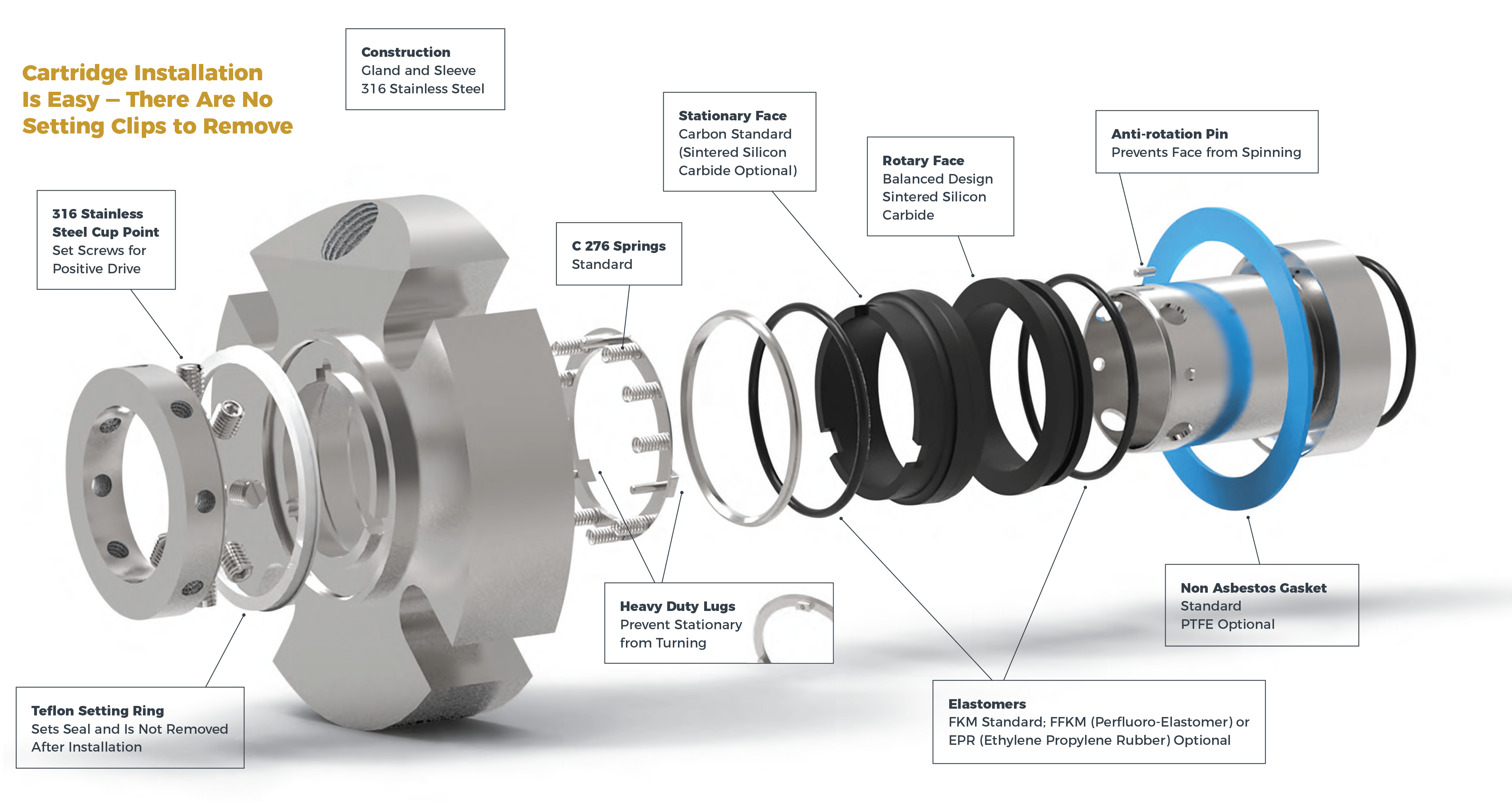
The stationary part of the seal is fitted to the pump housing with a static seal –this may be sealed with an o-ring or gasket clamped between the stationary part and the pump housing.
The rotary portion of the seal is sealed onto the shaft usually with an O ring. This sealing point can also be regarded as static as this part of the seal rotates with the shaft.
One part of the seal, either to static or rotary portion, is always resiliently mounted and spring loaded to accommodate any small shaft deflections, shaft movement due to bearing tolerances and out-of-perpendicular alignment due to manufacturing tolerances.
The primary seal is essentially a spring loaded vertical bearing - consisting of two extremely flat faces, one fixed, one rotating, running against each other. The seal faces are pushed together using a combination of hydraulic force from the sealed fluid and spring force from the seal design. In this way a seal is formed to prevent process leaking between the rotating (shaft) and stationary areas of the pump.
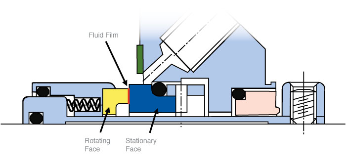
If the seal faces rotated against each other without some form of lubrication they would wear and quickly fail due to face friction and heat generation. For this reason some form of lubrication is required between the rotary and stationary seal face; this is known as the fluid film
In most mechanical seals the faces are kept lubricated by maintaining a thin film of fluid between the seal faces. This film can either come from the process fluid being pumped or from an external source.
The need for a fluid film between the faces presents a design challenge – allowing sufficient lubricant to flow between the seal faces without the seal leaking an unacceptable amount of process fluid, or allowing contaminants in between the faces that could damage the seal itself.
This is achieved by maintaining a precise gap between the faces that is large enough to allow in a small amounts of clean lubricating liquid but small enough to prevent contaminants from entering the gap between the seal faces.
The gap between the faces on a typical seal is as little as 1 micron – 75 times narrower than a human hair. Because the gap is so tiny, particles that would otherwise damage the seal faces are unable to enter, and the amount of liquid that leaks through this space is so small that it appears as vapor – around ½ a teaspoon a day on a typical application.
This micro-gap is maintained using springs and hydraulic force to push the seal faces together, while the pressure of the liquid between the faces (the fluid film) acts to push them apart.
Without the pressure pushing them apart the two seal faces would be in full contact, this is known as dry running and would lead to rapid seal failure.
Without the process pressure (and the force of the springs) pushing the faces together the seal faces would separate too far, and allow fluid to leak out.
Mechanical seal engineering focuses on increasing the longevity of the primary seal faces by ensuring a high quality of lubricating fluid, and by selecting appropriate seal face materials for the process being pumped.
When we talk about leakage we are referring to visible leakage of the seal. This is because as detailed above, a very thin fluid film holds the two seal faces apart from each other. By maintaining a micro-gap a leak path is created making it impossible for a mechanical seal to be totally leak free. What we can say, however, is that unlike gland packing, the amount of leakage on a mechanical seal should be so low as to be visually undetectable.

Rotating equipment engineers are responsible for avoiding unplanned downtime and making sure pumps are online and operational. As fluid system experts, Swagelok supports those responsibilities by designing and building seal support systems that are reliable, easy to maintain, and safe to operate. Our easy-to-configure, locally built, and reliable solutions help you reduce costs, save time, and improve safety.
Swagelok"s API 682 standard designs incorporate all the recommended components and adhere to best practices. For better operation and service of the seal and pump, we go beyond the standards to design systems specific to your application. This includes optional isolation valves, bypass loops, and instrumentation to assist the pump operator in both maintaining the system and monitoring the health of the seal.
Swagelok mechanical seal support systems are designed and built by your local authorized sales and service center how you want them and when you need them.
Swagelok’s fluid system expertise leverages design practices that maximize your seal support system’s operation and safe maintenance. And Swagelok products are backed by our Limited Lifetime Warranty.
Proper system start-up and commissioning are critical for the reliable operation of mechanical seals and their associated support systems. Inclusion of air within the system at start-up can lead to issues with the seal support system. Flow can be disrupted or stopped in systems with chillers or seal pots. Air inclusions can also prevent the support system from providing the desired rate of cooling. Swagelok design options include high-point vents in the seal support system, allowing the system to be vented and cleared of entrapped air.
System maintenance during turnarounds and projects requires seal support systems to be drained for servicing. When taking a pump out of service, including low point drains allows the system to be purged of buffer, barrier, or flush fluids, quickly and safely.
Pressure and temperature measurement devices help plant personnel understand what is happening in the seal chamber and seal support system. Many Swagelok seal support systems offer additional instrumentation options at points where measuring either pressure or temperature would assist in troubleshooting an issue or provide other operational benefit.
Whether the system delivers a flush fluid to the inboard seal or buffer and barrier fluids are circulated between seals in a dual seal arrangement, maintaining proper flow and circulation through the support system and seal chamber is a requirement for effective seal operation. A common flow issue is clogged orifices, which can cause a loss of flush fluid to the seal chamber, resulting in seal failure. Additionally, improper circulation of buffer and barrier fluids can also cause operational issues due to lack of appropriate system cooling.
When designing seal support systems, it is important to have pressure drop and flow control happen at appropriately engineered locations, such as orifices and flow control valves. Components such as filters and strainers can become clogged and create unwanted flow restrictions in seal support systems. These serviceable items should be located in areas that are easy to access and maintain. Additional options such as bypass loops can be added to the system to ensure a continued supply of flush fluid when a filter or strainer element is being replaced or cleaned.
In addition to individual system components that will need to be serviced, the design of tubing runs should be considered critical to the effectiveness of seal support systems. All tubing runs should be sloped, especially those running to and from the seal. A half inch per foot (40 mm per meter) of slope is recommended. One-half inch (12 mm) OD tubing is acceptable for differential pressure or pumped flow systems, while 3/4 inch (18 mm) tubing is recommended for systems utilizing a pumping ring or a thermosyphon effect. It is best practice to eliminate the use of elbow fittings and to use large-radius bends in the tubing to further assist flow.
API 682 recommends specific wall thicknesses for 1/2 inch (12 mm) to 1 inch (25 mm) OD tubing. While thinner-walled tubing, such as that used in general instrumentation installations, is often sufficient to handle the pressure and temperature of seal support systems, heavier-wall tubing provides extra rigidity in high-vibration service. Tubing with a heavier wall also creates systems that are more robust in areas where large pieces of equipment are being maintained and personnel may inadvertently come into contact with the tubing.
In contrast to larger liquid systems which mainly use 1/2 inch (12 mm) and 3/4 inch (18 mm) tubing, API 682 offers no guidance regarding tubing wall thickness for systems under 1/2 inch (12 mm). Tubing wall thickness for 1/4 inch (6 mm) and 3/8 inch (8 mm/10 mm) systems can be selected from Swagelok"s Tubing Data Sheet, MS-01-107, based on the pressure and temperature of the service. These systems are typically nitrogen filtering and regulating systems for gas seal plans. Swagelok recommends these API gas plans are mounted on a panel with commonly serviced items such as filters and regulators placed with ease of maintenance in mind.
One final safety consideration when choosing the appropriate design for an API 682 plan is the incorporation of block-and-bleed valveson all instruments, including gauges. This recommendation by API adds an additional level of safety for items that need to be calibrated or removed for servicing. Wherever practical, Swagelok seal support systems offer options including 2-valve manifolds or other appropriate isolation on instruments.

The scope of our mechanical seal product range far exceeds any other seal manufacturer. From small elastomer bellows seals used in millions of domestic water pumps to double mechanical seals that ensure maximum sealing safety and large, highly customized dry-running gas seals for mission critical high speed turbo compressors, John Crane has the right product for any application.
Our world-class rotating equipment technologies, paired with an unmatched breadth of applied engineering expertise, meet virtually all international standards including API 682 and help plants reduce maintenance costs, slash down time and improve reliability. When it comes to keeping your rotational equipment running 24/7, John Crane’s comprehensive range of mechanical seals and systems has you covered.
A range of seals for mission-critical applications, designed to solve the application-specific challenges of each industry. From API 682 compliance for the oil and gas industries, using gas seal technology on our innovative pump gas seals to eliminate fugitive emissions, dealing with slurry in the mining and minerals processing industries, to the difficulties associated with maintenance on large pumps and rotating equipment — we have a solution.
Dry-running, non-contacting gas seals have been the industry standard since the early 1980s for turbomachinery. John Crane gas seals, separation seals and support, monitoring, control and conditioning systems — the heart of any reliable sealing solution — are constantly evolving to meet the needs of customers. The product portfolio is supported by unrivaled global service capability providing repair, retrofit, gas seal storage and reliability expertise, delivering total solutions throughout the product lifecycle.
In industries like chemical, pharmaceutical, pulp and paper, and food and beverage, safeguarding and compliance with industry standards, avoiding contamination and efficiency are always top priorities. Our range of vessel and agitator seals optimize equipment performance, maintain product purity and conform to industry regulations, no matter where you are.
Our range of mechanical seals, packing and bearing isolators combines advanced, thoroughly proven technologies with extensive industry expertise to create a range of products characterized by innovative design concepts and outstanding manufacturing quality. Tried, tested and effective solutions for virtually any application that deliver robust performance, reduced installation times and lower maintenance costs.
Create the optimum operating environment that will ensure outstanding seal performance and reliability. Our comprehensive range of engineered pressure reservoirs, gas seal control panels, heat exchangers and abrasive separators can be combined to produce the perfect seal support system for any application.
Designed to overcome rigorous challenges, our comprehensive suite of seal face technologies combat limited seal face lubrication that adversely affects reliability, cost and durability. Our engineers designed these face treatments to extend rotating equipment life through advanced micro machined patterns and features improving seal face lubrication that optimizes equipment performance. We deliver the right face technology for the right application.
A crucial step in preventative maintenance in pumps is finding and using the correct seal for the job. Mechanical seals are used to seal the rotating shaft in pumps and other equipment. With so many mechanical seal designs on the market, it can be difficult to identify which kinds to use. A.W. Chesterton Company’s mechanical seal design utilizes 5 design principles to maximize its sealing capabilities. These principles have been refined by Chesterton since the company brought its first mechanical seal to market in 1970. After all the lessons learned from successes and failures, they have determined the Five Key Features that a mechanical seal should have to reduce unplanned maintenance and downtime. To provide the greatest mean time between failures (MTBF) and avoid downtime, they utilize these five design principles in their sealing devices.
Typically, within early mechanical seal designs, the springs were submerged within the fluid. However, this can lead to trouble when fluids with dirt or other contaminates interact with the springs. When the contaminates collect within the spring, it cannot correctly maintain the alignment necessary for a complete seal. Chesterton’s mechanical seal design protects the springs within the mechanical seal from the fluids being pumped.
The second design feature and open secret of Chesterton’s mechanical seal design is balance. On the mechanical seal, there are two main sides, the fluid side, and the atmospheric side. To prevent moisture from leaking out of the seal, both sides put equal pressure on each other to trap the fluid. Many seals will often see that the fluid side exerts greater pressure than the atmospheric side. Not only does this reduce the quality of the seal, but it can also ruin the pump with time. Balanced seals reduce the seal ring area on which the hydraulic pressure of the liquid in the pump acts. This allows for better lubrication that results in lower heat generation, face wear, and power consumption. Balanced seals will generally have higher pressure ratings than unbalanced seals.
Fretting on a pump shaft refers to the way that a material is worn away on a shaft by an elastomeric material. An example may be a 316 stainless steel shaft sleeve that is damaged by a Viton O-ring. Stainless steel protects a shaft from corrosion by forming a chrome oxide layer on the surface. The dynamic O-ring wears that protective surface away and it then reforms. Over time the chrome oxide gets imbedded into the O-ring and works like sandpaper removing even more material. The result is a groove worn into your expensive sleeve and a leaking mechanical seal. Chesterton seals utilize designs that have any dynamic O-rings operating against a non-metallic surface, usually the sacrificial face.
Additionally, some manufacturers offer seals that are self-fretting, rather than shaft-fretting. What this means is that these seals do not fret or damage the shaft, they harm seal itself. While this protects the pumps, the O-rings still work against metal, reducing the lifespan of the seal itself.
Some mechanical seal designs utilize an inserted seal face, typically made of carbon or graphite inserted into a metal holder. However, the disadvantage to this technique is these non-metallic materials often react to heat differently than the metal of the seal. The result is the face of the seal is easily deformed- leading to leaks and early replacement of the seal. Proper mechanical seal design uses monolithic seal faces without using a holder and inserted face. By using Finite Element Analysis (computer modeling), Chesterton’s monolithic seal face designs are made more efficiently than ever.
Mechanical seals can either use rotating or stationary springs. With rotary mechanical seals, it is important that the stuffing box face is perpendicular to the shaft for the faces to stay closed. There will always be some resulting misalignment from installation and parts tolerances so this alignment cannot be assured. To compensate for the misalignment, the springs must adjust each time the shaft rotates to keep the seal faces closed. At motor speeds this adjustment happens thousands of times per minute (for 1800 rpm, 3600 adjustments occur) which is not only difficult to accomplish, the springs will fatigue and fail causing seal failure. Rotary seals are simple in design which makes them inexpensive
In contrast, a stationary seal is designed in such a way that the springs do not rotate with the pump shaft; they remain stationary. Because the springs do not rotate, they are unaffected by the rotation of the shaft or how fast the shaft rotates. The springs do not need to correct or adjust with each rotation; they adjust for misalignment only once when installed. Chesterton uses this as the fifth design requirement, and this provides greater life to their mechanical seals.
Using these five design principles, Chesterton has updated its 150 seals to the new 1510 seal. The new design uses a monolithic seal face and changes where the dynamic O-rings are placed to be a non-fretting seal. Chesterton unveiled this updated seal in the US in September of 2022. However, Chesterton also has one additional add-on for this new seal. Starting at the end of October 2022, Chesterton will be releasing the 1510L. The 1510L has all the same design capabilities of the 1510, the difference between the two is the installation process. The 1510L utilizes a lock ring mechanism to simplify installation requiring the installer to tighten only one screw to connect the seal to the shaft.
To request a demonstration for the 1510L mechanical seal, click here. Learn more about Northwest Pump’s mechanical seals by contacting us here, emailing us at sales@nwpump.com, or by calling 1-800-452-PUMP.
For service on your mechanical seals by our Chesterton certified pump technicians, contact us here, email us at service@nwpump.com, or call 1-866-577-2755.

This double mechanical seal allows for a new, higher level of reliability and performance with the convenience of a cartridge seal. The Chesterton 280™ Double Mechanical Seal is specifically designed to handle demanding, high-torque applications.
This product is an ideal selection for such difficult applications as high concentration black liquor, hard-to-seal monomers such as acrylonitrile, vinyl chloride monomer, and any other potentially viscous solidifying liquids.
An end-face mechanical seal is a device used on a rotating shaft to keep fluids in and contaminants out. It prevents the fluid moved through an asset, most often a centrifugal pump, from leaking. These seals are located in the asset’s stuffing box or seal chamber. This is the area of the pump where the pump shaft connects to the drive (an electric motor, for example).
Except for air seals, which will be discussed later, most types of mechanical seals consist of two flat faces that are installed perpendicular to the shaft. One of the faces is mounted stationary to the seal chamber housing. The other face rotates with the shaft to provide the primary seal. Axial mechanical force and fluid pressure maintain the contact between the seal face materials. This contact prevents leakage and retains the fluid within the pump.
Component, end-face mechanical seals consist of a separate rotating member and a stationary seat that mount in a gland or housing. Since they are not preset, installation and maintenance are more complicated than cartridge seals. Installing these requires experienced technicians who can properly install and adjust them.
Air seals are noncontacting, pneumatic devices engineered to seal rotating shafts. These seals are primarily installed in dry powder or slurry applications. They protect against product loss, emissions, and contamination by using small amounts of air or inert gas. This air is throttled to create positive pressure and an effective seal.
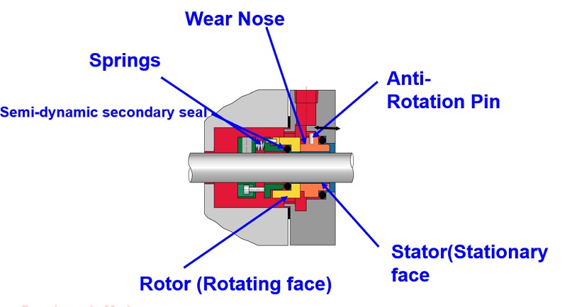
Most mechanical seals have five parts:Rotating primary face– Fixed to and rotates with the shaft and seals against the stationary primary sealing element
Stationary primary face– Fixed to the stationary housing of the pump, mixer or other equipment through which the rotating shaft passes and seals against the rotating primary sealing element
Mechanical loading devices– Biases the primary sealing elements in contact to initiate sealing. These can be a single spring, multiple springs, wave springs, or metal bellows.
Static and/or dynamic secondary seals– Seal between the mechanical seal components and the equipment shaft and housing that compensates for any shaft movement that may damage the seal faces.
In summary, knowing the mechanical seal types and the parts that make them up is only the beginning. Assessing the application, installation, and operation (with leakage limits) helps determine which seal type will be selected and how well it will perform in the system. This important decision factors into overall system reliability.

The rotating shaft of a centrifugal pump penetrates the back end of a pump casing through a stuffing box or seal chamber. The primary purpose of a mechanical seal in a centrifugal pump is to prevent fluid from leaking to the atmosphere along this rotating shaft. Selection of the right mechanical seal for each pump application is critical when considering safety and reliability. Mechanical seal failure is typically one of the primary reasons why pumps fail. In this guide, the experts at PumpWorks will show you the steps to install a mechanical seal in your centrifugal pump with minimal downtime.
A mechanical seal requires two extremely smooth and flat (lapped) seal faces in contact, one rotating with the shaft and the other stationary with the casing. These seal faces are sealed to their appropriate holders through the use of secondary seals (o-rings or gaskets). The faces are mechanically energized and flexible so that they can be placed into contact and move to make up for static and dynamic misalignments as well as wear. The seal faces require lubrication from the fluid and break down this fluid as it tries to escape through the seal faces, resulting in slight vapor release. All mechanical seals leak…vapor…when selected and sized correctly.
You may be wondering how long the mechanical seal installation procedure will take. By following the 10 simple steps listed below, you’ll have the job done in no time.
If your pump is a ‘back pull-out’ design, remove the spacer element in the pump coupling. Then remove the casing bolts and slide the remainder of the pump away from the casing. You are now able to access the mechanical seal without having to disconnect the casing from the inlet and outlet piping. If the pump is not a ‘back pull-out’ design, you will need to disconnect the complete pump after disconnecting the coupling between the pump and motor shaft. If the pump is a close coupled design (the pump uses the shaft of the motor as its shaft and the motor directly bolts onto the back of the pump), you will need to remove the entire pump/motor. Remove the casing bolts and remove the casing.
The mechanical seal is located behind the impeller on the pump shaft. Impellers are either screwed onto the shaft or held in place via a bolt. To remove the screwed-on impeller from the shaft, use a wrench to hold the shaft in place and rotate the impeller clockwise until it is completely unscrewed. To remove a bolted impeller, hold the shaft in place and remove the bolt.
You can now directly access both the rotary and stationary seal parts. The rotary parts are typically held in place along the shaft using set screws. Remove the set screw and slide off the rotary seal parts. Remove the stationary part of the seal from the casing or seal chamber bore.
Now it’s time to place a new mechanical seal onto the shaft. Carefully slide the replacement seal parts along the shaft. Using a new o-ring or gasket material, press the stationary part into the casing or seal chamber bore. Follow the instructions for setting the rotary portion back onto the shaft correctly. This is a crucial step.
CAUTION: Always install mechanical seals in a clean working space. Don’t touch the front of the seal faces as it is susceptible to body oils and may not function properly if compromised. Keep the seal in its packaging until it’s time to install.
Always review safety precautions found in the pump IOM. Always use the Pump IOM when working on any pump. Install the mechanical seals using the specific instructions from the mechanical seal manufacturer. Lastly, always make sure the pump and motor are realigned within 001” – 002”. Misalignment will cause premature mechanical seal failure.
PumpWorks is the go-to company for all your mechanical seal installation needs. Our pump manufacturing company offers over 30 years of experience in the troubleshooting, selection, application, and repair of mechanical seals. We serve a wide range of process industries such as petroleum refining, chemical, food and beverage, water and wastewater, power, and more.
Power machines that have a rotating shaft, such as pumps and compressors, are generally known as “rotating machines.” Mechanical seals are a type of packing installed on the power transmitting shaft of a rotating machine. They are used in various applications ranging from automobiles, ships, rockets and industrial plant equipment, to residential devices.
Mechanical seals are intended to prevent the fluid (water or oil) used by a machine from leaking to the external environment (the atmosphere or a body of water). This role of mechanical seals contributes to the prevention of environmental contamination, energy saving through improved machine operating efficiency, and machine safety.
Shown below is a sectional view of a rotating machine that requires the installation of a mechanical seal. This machine has a large vessel and a rotating shaft at the center of the vessel (e.g., a mixer). The illustration shows the consequences of cases with and without a mechanical seal.
If the aim is solely to prevent leakage from the machine, it is effective to use a seal material known as gland packing on the shaft. However, a gland packing tightly wound around the shaft hinders the motion of the shaft, resulting in shaft wear and therefore requiring a lubricant during use.
To ensure this, each part is fabricated according to a precise design. Mechanical seals prevent leakage even with hazardous substances that are difficult to mechanically handle or under harsh conditions of high pressure and high rotating speed.
A mechanical seal is installed on the impeller rotating shaft. This prevents the liquid from leaking through the clearance between the pump body and the shaft.
The face materials where the stationary ring and the rotary ring rub against each other are the most important portions as a barrier to the fluid. If the clearance is too small, the friction increases, hindering the shaft motion or resulting in seal breakage. Conversely, if the clearance is too large, the liquid will leak. Consequently, it is necessary to control the clearance in the order of micrometers to prevent leakage, but at the same time ensuring lubrication by the fluid, thereby reducing the sliding torque and avoiding hindrance to the machines’ rotation.
The mechanical seal technology is a sum of mechanical engineering and physical property technology due to the above-mentioned functions and applications. More specifically, the core of the mechanical seal technology is the tribology (friction, wear and lubrication) technology used to control the surfaces where the stationary and rotary rings rub (slide) against each other.
Mechanical seals with improved functionality will not only prevent the liquid or gas handled by a machine from leaking to the outside, but also improve machine operating efficiency, thereby helping achieve energy saving and prevent environmental contamination. Moreover, in some cases, rotating machines handle media that, in the case of leakage, can lead to a dangerous accident. Therefore, mechanical seals are required to be highly reliable through manufacturing backed by solid engineering expertise.
These functions and roles will make mechanical seals increasingly important functional parts in the future. Their further technical innovation is anticipated. To positively respond to these expectations, Eagle Industry is working on technical research and development every day.
The mechanical seal technology was fundamentally established in the 1960s. Thereafter, it has been making significant progress by introducing various leading-edge technologies, and innovative mechanical seals created from the above advanced technology are continuously being put to practical use.
To meet the demands of the market sufficiently, an applicable range of the “pressure” and “rotation speed” of mechanical seals has been considerably extended since the beginning of the 2000s. This is due to advancing of the tribology technology such as to enhance a function of the sliding materials (e.g., composite material composition, coating technology) and/or a performance of the sliding surfaces based on the fluid lubrication theory (e.g., non-contact mechanical seal, surface textured mechanical seal). These advanced technologies are sustained by improvement in the element technology of numerical analysis, processing/production, physical property/composition analysis, measurement, verification test, and so on.


 8613371530291