
mechanical seal diagram quotation

Mechanical seals are critical components in centrifugal pump systems. These devices preserve the integrity of the pump systems by preventing fluid leaks and keeping contaminants out. Mechanical seal systems are used on various seal designs to detect leakage, control the seal environment and lubricate secondary seals.
Depending on the pump type and the process variables, there are various mechanical seal types to choose from. Each seal variant has its unique design and characteristics which make it suitable for a specific application. MES has years of experience with industrial mechanical seals and support systems, making us an authority in this area.
Mechanical seal types vary in design, arrangement, and how they disperse the hydraulic forces acting at their faces. The most common seal types include the following:
Balanced mechanical seal arrangements refer to a system where the forces acting at the seal faces are balanced. As a result of the lower face loading, there is more even lubrication of the seal faces and longer seal life. Learn about our mechanical seal lubrication systems today.
Balanced mechanical seals are particularly suited to higher operating pressures, typically above 200 PSIG. They are also a good choice when handling liquids with low lubricity and higher volatility.
Unbalanced mechanical seal types are commonly employed as a more economical option to the more complex balance seal. Unbalanced seals may also exhibit less product leakage due to tighter control of the face film, but as a result can exhibit much lower mean time between failure. Unbalanced seals are not recommended for high pressure or most hydrocarbon applications.
Pusher seals utilize one or multiple springs to maintain seal closing forces. The springs can be in the rotating or stationary element of the mechanical seal. Pusher type seals can provide sealing at very high pressures but have a drawback due to the elastomer under the primary seal face that can be subjected to wear as the face moves along the shaft/sleeve during operation.
Non-pusher seals utilize a metal or elastomeric bellows to maintain seal closing forces. These seals are ideally suited to dirty and high temperature applications. Bellows seals are limited to medium/lower pressure applications.
Conventional seals are typically lower cost and often installed on general service equipment. These seals require higher operator skill to service as they installed as individual components.
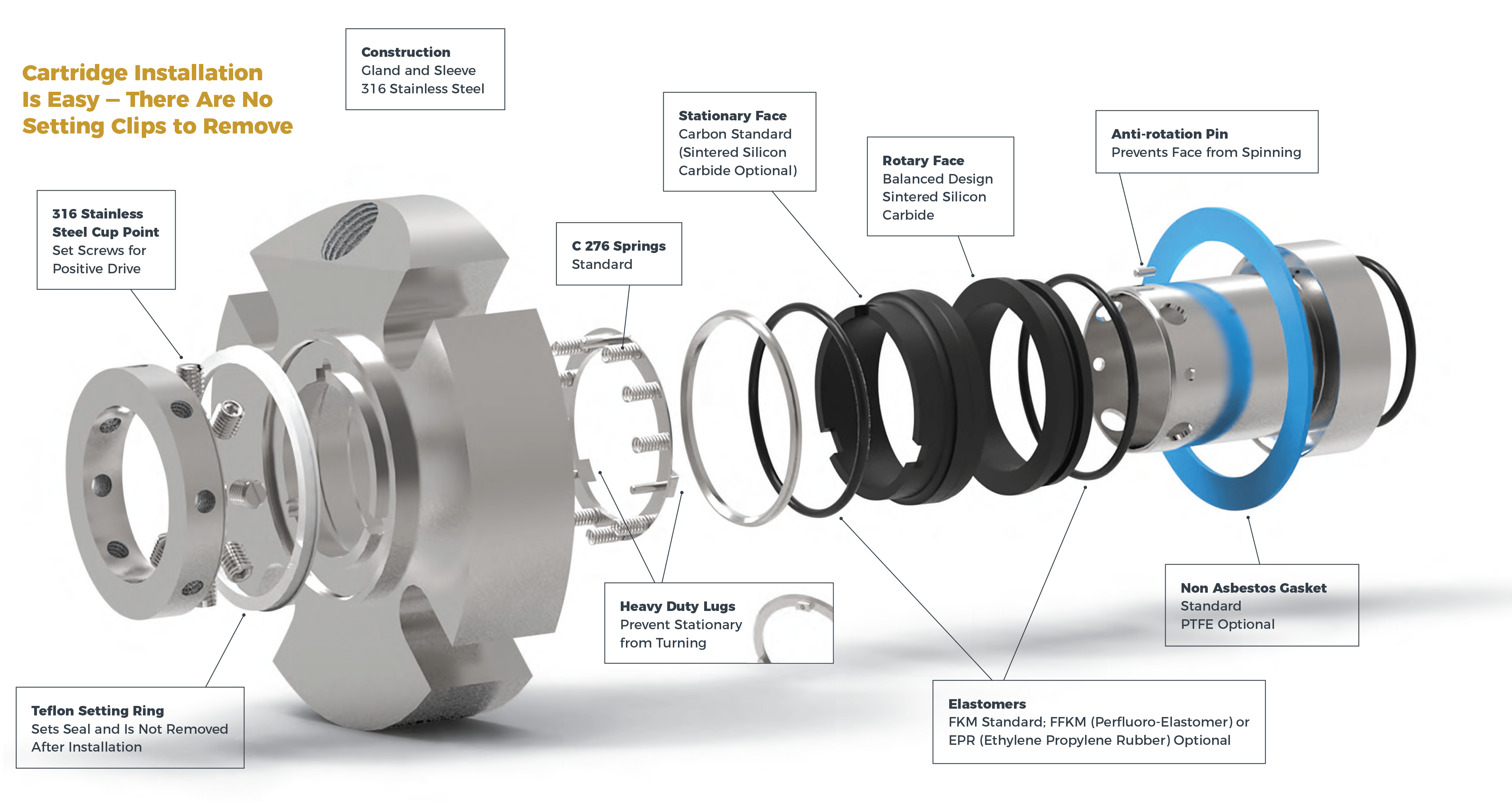
Cartridge type mechanical seals incorporate all of the seal elements into a single assembly. This dramatically reduces the potential for assembly error and the time require for seal replacements. Learn more about the difference between cartridge and non-cartridge mechanical seals today.
When deciding on the type of seal system for a centrifugal pump, operators must choose according to their unique application. Failure to select the proper seal type can lead to loss of pump integrity, breakdowns and costly repairs. To avoid these undesirable results, all operators must consider the following factors before deciding.
The amount of pressure exerted at a mechanical seal’s faces has a significant effect on its performance. If a pump is to be operated at low pressures, an unbalanced mechanical seal will be suitable. However, in conditions where higher pressures are anticipated, balanced seals will prove a more reliable solution.
Balanced mechanical seals perform better than their unbalanced counterparts in conditions where the operating temperatures are higher than normal. Heat sensitive components are better preserved in balanced mechanical seals compared to other seal types.
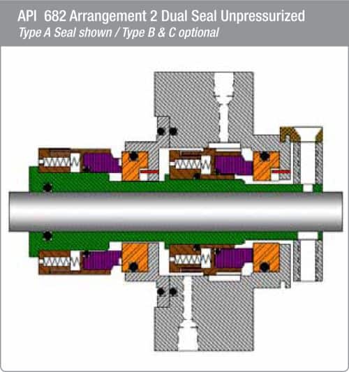
As it goes for all types of machinery, operator safety is the top priority. The use of double mechanical seals in centrifugal pumps provides additional protection as they have increased sealing capacity and are generally more reliable.
The Style 57 design serves to keep the sealing faces in contact and positively transmits the drive evenly 360° around the full circumference of the rotary face. This is accomplished by the special spring design, which provides an interference fit. The compression spring is wound either right or left hand depending on shaft rotation.
The scope of our mechanical seal product range far exceeds any other seal manufacturer. From small elastomer bellows seals used in millions of domestic water pumps to double mechanical seals that ensure maximum sealing safety and large, highly customized dry-running gas seals for mission critical high speed turbo compressors, John Crane has the right product for any application.
Our world-class rotating equipment technologies, paired with an unmatched breadth of applied engineering expertise, meet virtually all international standards including API 682 and help plants reduce maintenance costs, slash down time and improve reliability. When it comes to keeping your rotational equipment running 24/7, John Crane’s comprehensive range of mechanical seals and systems has you covered.
A range of seals for mission-critical applications, designed to solve the application-specific challenges of each industry. From API 682 compliance for the oil and gas industries, using gas seal technology on our innovative pump gas seals to eliminate fugitive emissions, dealing with slurry in the mining and minerals processing industries, to the difficulties associated with maintenance on large pumps and rotating equipment — we have a solution.
Dry-running, non-contacting gas seals have been the industry standard since the early 1980s for turbomachinery. John Crane gas seals, separation seals and support, monitoring, control and conditioning systems — the heart of any reliable sealing solution — are constantly evolving to meet the needs of customers. The product portfolio is supported by unrivaled global service capability providing repair, retrofit, gas seal storage and reliability expertise, delivering total solutions throughout the product lifecycle.
In industries like chemical, pharmaceutical, pulp and paper, and food and beverage, safeguarding and compliance with industry standards, avoiding contamination and efficiency are always top priorities. Our range of vessel and agitator seals optimize equipment performance, maintain product purity and conform to industry regulations, no matter where you are.
Our range of mechanical seals, packing and bearing isolators combines advanced, thoroughly proven technologies with extensive industry expertise to create a range of products characterized by innovative design concepts and outstanding manufacturing quality. Tried, tested and effective solutions for virtually any application that deliver robust performance, reduced installation times and lower maintenance costs.
Create the optimum operating environment that will ensure outstanding seal performance and reliability. Our comprehensive range of engineered pressure reservoirs, gas seal control panels, heat exchangers and abrasive separators can be combined to produce the perfect seal support system for any application.
Designed to overcome rigorous challenges, our comprehensive suite of seal face technologies combat limited seal face lubrication that adversely affects reliability, cost and durability. Our engineers designed these face treatments to extend rotating equipment life through advanced micro machined patterns and features improving seal face lubrication that optimizes equipment performance. We deliver the right face technology for the right application.
Mechanical seals form a critical part of any mechanical operation involving fluid movement through rotational shafts, such as in the case of pumps. These seals ensure that the fluid does not leak out of a closed system and contaminants do not enter the system. In pumping applications, mechanical seals are placed at the point of entry or exit of a rotating shaft, preventing the pressurized fluid from escaping the pump housing and withstanding the friction generated from the shaft rotations.
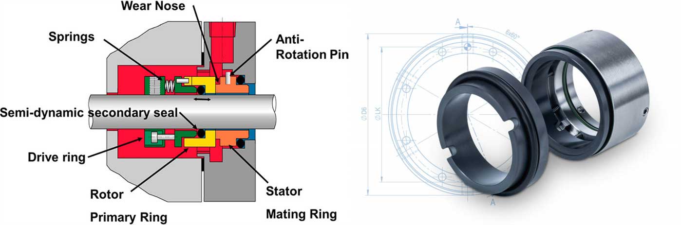
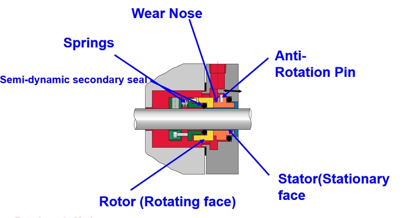
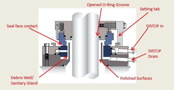
Mechanical seals are devices that accommodate a rotating shaft while containing and preventing the fluid from leaking out of the enclosed housing. While different mechanical seal designs are available for pumping applications, most have three sealing points.
These three sealing points ensure that the fluid contained within the pump housing does not leak while also preventing dust particles in the atmosphere from entering the housing.The mechanical seals are usually made up of different materials to prevent sticking. Typically, one side of the seal uses softer materials like carbon graphite, and the other is made of harder materials such as silicon carbide or ceramic alumina. However, hard materials are preferred for both surfaces if the pumping application involves abrasive fluids.
In addition to the two materials, the sealing unit also comes with O-rings to seal the stationary face on the housing side and the rotating face on the shaft side. Springs are also used to keep both faces pressed.
In most cases, the two faces of the seals are also lubricated to prevent friction and wear. Depending on the application, this fluid film can either be a separate lubricant or the process fluid itself.
Mechanical seals can be selected based on the type of pump application. Choosing the wrong seal can affect pump performance and lead to damage and costly repairs.An unbalanced mechanical seal is preferred if the pump needs to operate at a lower pressure. However, high pressure pumping applications require balanced mechanical seals. Balanced seals also perform better in high temperature operating conditions. Cartridge seals require less maintenance but are more expensive, hence used for limited applications.
At Hayes Pump, we have a fully staffed, factory-trained parts department to help you quickly with the correct mechanical seal for your pump. You canrequest a quotefor your part orcontact usto get further assistance.

We specialize in hard-to-find seals and demanding applications. Our extensive network of resources enables us to locate the right manufacturer and part, every time.
At All Seals we know down time is not an option. We specialize in hard-to-find seals and demanding applications. With over 40 years of experience in supplying quality replacement mechanical seals, we can help you identify the seal you need and solve your sealing problem. Our technical staff is available to help you – just give us a call. Our comprehensive stock of components ensures that we can build almost any seal combination for same day shipment. Whether you need a new seal or you have a seal to be repaired, we welcome the opportunity to help you with your rotary sealing needs.
We carry a comprehensive inventory of mechanical seal components, which allows us to build the right seal for your application. We’ll even design custom seals for one-of-a-kind applications.
Need hard faces or specialty elastomers? Give us a call. We can quickly build a repair kit to withstand any medium being pumped. You’ll find All Seals’ pump repair kits an invaluable part of your operation.
The FSI 3000 Series mechanical seal is a multiple spring design available in both balanced and unbalanced configurations. The basic 3B/3B-1 can be offered for single, dual, or tandem operation. Most 3000 Series mechanical seals are custom engineered designs due to operating conditions and / or equipment type.

A mechanical seal is simply a method of containing fluid within a vessel (typically pumps, mixers, etc.) where a rotating shaft passes through a stationary housing or occasionally, where the housing rotates around the shaft.
The stationary part of the seal is fitted to the pump housing with a static seal –this may be sealed with an O-Ring or gasket clamped between the stationary part and the pump housing.
The rotary portion of the seal is sealed onto the shaft usually with an O ring. This sealing point can also be regarded as static as this part of the seal rotates with the shaft.
One part of the seal, either to static or rotary portion, is always resiliently mounted and spring loaded to accommodate any small shaft deflections, shaft movement due to bearing tolerances and out-of-perpendicular alignment due to manufacturing tolerances.
While two of the sealing points in a seal design are simple static seals, the seal between the rotating and stationary members needs a little more consideration. This primary seal is the basis of all seal design and is essential to its effectiveness.
The primary seal is essentially a spring loaded vertical bearing - consisting of two extremely flat faces, one fixed, one rotating, running against each other. The seal faces are pushed together using a combination of hydraulic force from the sealed fluid and spring force from the seal design. In this way a seal is formed to prevent process leaking between the rotating (shaft) and stationary areas of the pump.
If the seal faces rotated against each other without some form of lubrication they would wear and quickly fail due to face friction and heat generation. For this reason some form of lubrication is required between the rotary and stationary seal face; this is known as the fluid film
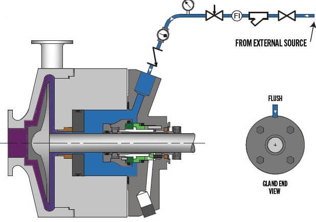
In most mechanical seals the faces are kept lubricated by maintaining a thin film of fluid between the seal faces. This film can either come from the process fluid being pumped or from an external source.
The need for a fluid film between the faces presents a design challenge – allowing sufficient lubricant to flow between the seal faces without the seal leaking an unacceptable amount of process fluid, or allowing contaminants in between the faces that could damage the seal itself. This is achieved by maintaining a precise gap between the faces that is large enough to allow in a small amounts of clean lubricating liquid but small enough to prevent contaminants from entering the gap between the seal faces.
Replacement seals for Cornell Pumps® Mechanical Seals products. Search by the OEM Part Number using the SEARCH function at the top of the page or use search by specification.
OEM names, brands, model or part numbers are for identification purposes only. Our components are designed to provide performance and service life equal to or better than the OE part when properly installed and properly applied. Springer Parts® carry a warranty equal to the OE component. Cornell Pumps® Mechanical Seals is a registered trademarks of its respective company. Springer Pumps, LLC is not a representative of, nor affiliated with Cornell Pumps® Mechanical Seals.
Grundfos mechanical seal GRF-D is a kind of seal for grundfos air conditioning pumps, like CH2-30, CH4-30, CH8-12, also working for SPK1, SPK2, SPK4,SPK8 grundfos pumps.
People can use carbon, silicon, and tungsten carbide for this mechanical seal as seal face, if for high temerperature, we suggest to choose rubber seal viton for the rubber parts.
It is a low cost seal in grundfos mechanical seal series, popular using in many factories. We follow original grundfos seal design 100%, and make sure all mechanical seal from factory can fit the grundfos pump perfect.
Guangzhou Lepu machinery CO., LTD becomes one of the leading mechanical seal supplier in south of china, we focus in designing and manufacturing mechanical seal for many kinds of famous brand pumps, our mechanical seal cover many kinds of industry like food, petrol chemical, paper making, sea ship, and so on.
1. Guangzhou Lepu Machinery CO., LTD is a manufacturing company based in China. We have been providing quality grundfos mechanical shaft seals throughout our region and beyond.
3. Lepu makes decisions to achieve to be a nationally professional grundfos mechanical seal catalogue supplier. Ask! We always stick to high quality for grundfos seal . Ask! Accurate market positioning of Lepu Machinery allows you the highest return on investment. Ask! Lepu will never give up on its ambition to serve each customer well. Ask!
A seal is required to keep lubrication in and contaminants out of a cavity where lubricants are stored - a "controlled seal cavity." The non-contact seal is designed specifically for applications where lubrication must be kept from leaking out of a controlled fluid cavity located between two elements.
A typical seal application involves a stationary element, a non-stationary (or rotating) element, and a controlled fluid cavity between these two elements (See Fig. 1). Traditionally, simple lip seals have been applied in this type of environment.
Initially, non-contact seals were developed as a sealing method that would operate in extremely high shaft speed environments, or in applications where the durability of a traditional lip seal was limited. The contact lip seal has the stationary sealing element, or lip, in contact with the rotational element. This constant contact creates wear on both the lip and the rotating element, and adds significant parasitic drag to the system. In addition, operating speed is limited in these applications due to overheating and wear on the contact lip of the seal, as a result of rubbing between the rotating and non-rotating surfaces. Ultimately the seal lip will melt or centrifugally lift from the contact surface as operating speeds increase.
Non-contact seals are designed to seal without any physical contact between the rotating and stationary elements. In general, the benefits of non-contact seals include:
The type of non-contact seal chosen for an application determines its specific benefits. The key to successfully employing any non-contact seal is to understand the sealing methods, and to select the appropriate seal configuration for each specific application.
Each type of seal has specific advantages and limitations. To determine the applicability of each seal, the engineer must examine the performance of the seal during each of three normal operating modes:
There are several types of labyrinth seals. Typical labyrinth seals incorporate a "maze" or a set of rings in extremely close proximity, to capture the lubrication and push it back toward the controlled fluid cavity. Rings in close proximity form a barrier by shearing the fluid, centrifugally slinging the lubricants from the rotating seal element to the stationary seal element in a series of steps (See Figure 2).
The labyrinth seal is constrained in its ability to function with a wide variety of fluids due to its limited ability to centrifugally push the lubricants back into the controlled fluid cavity. In addition, it can only handle a limited volume of lubricating fluid in the controlled fluid cavity, and it requires high rotational speeds to seal adequately. The seal is not able to keep out external environmental contaminants entering the controlled fluid cavity when the seal is not rotating, and some fluid "weepage" is expected from the seal. In general, the standard labyrinth type seals have limited abilities when reviewed in terms of the three operational modes:
When the seal is not rotating, the controlled fluid cavity is open to the outside environment. The fluid that is contained in the seal can migrate to the bottom of the seal and possibly weep out of the seal. The length of time the seal is stationary will affect the amount of weepage.
When the shaft is accelerating, the seal is accelerating and the fluid within the controlled fluid cavity must remain in laminar flow, or splashing will occur and the seal will leak. Splashing can be controlled somewhat by selecting a lubricant with high viscosity. The seal is designed to push the fluid back into the controlled fluid cavity, but it will also push any contaminants that have entered the stationary shaft into the controlled fluid cavity. The fluid level in the cavity must also be limited to ensure the fluid does not splash and flow past the seal.
When rotating at the normal operating speed, the labyrinth seal pushes any fluid trying to exit the controlled fluid cavity back into the seal cavity. The normal speed range required will depend on the specific seal chosen but, in general, high speeds are required to maintain consistent behavior. During operation, the seal is open to contaminants entering from the outside environment. The rotating element and the stationary element in the labyrinth seal must remain axially aligned during operation and any axial movement between the two elements or vibration in the application could cause the seal to leak.
The hybrid labyrinth seal has been modified by adding a contact seal component designed to centrifugally lift off the rotating shaft when the seal is operating at normal speeds. This modification solves some of the limitations of the standard labyrinth seal, and makes it function more like a contact lip seal. In addition, a lip seal component can be incorporated such that it will only make contact at lower speeds and will centrifugally lift from the contact surface at higher speeds. While the hybrid labyrinth seal does solve the problem of contaminants entering the controlled fluid cavity when the seal is not rotating, it adds challenges in mounting the seal
In general, the hybrid labyrinth type seals have limited capabilities when reviewed in the three operating modes, but in the proper applications they can perform adequately. Hybrid labyrinth type seals offer additional features over the standard labyrinth seal but still have some limitations:
When the seal is not rotating, the controlled fluid cavity is not open to the outside environment but some weepage is possible because the lifting mechanism must be capable of moving in and out radially. The fluid that is contained in the seal can also migrate to the bottom of the seal and weepage of fluid out of the seal is possible. The length of time the seal is stationary affects the amount of weepage.
When the shaft is accelerating, the seal is accelerating and the fluid within the controlled fluid cavity must remain in laminar flow or splashing will occur and the seal will leak. Splashing can be controlled on a limited basis by selecting a lubricant with high viscosity. The seal will also have some parasitic drag torque until the contact element in the seal is centrifugally lifted from the contact surface. The splashing problems from acceleration and deceleration will be similar to those of the standard labyrinth seal when the seal is operating at speeds high enough to centrifugally lift the contact element from the rotating shaft. Operating speeds are critical to ensure proper operation of the seal.
When rotating at normal operating speed, the hybrid labyrinth seal pushes any fluid trying to exit the controlled fluid cavity back into the seal cavity. The speed range required will depend on the specific seal chosen but, like the standard labyrinth seal, high speeds are required to maintain consistent operation. The seal is also open to contaminants entering from the outside environment, and the seal will push these contaminants into the seal cavity during operation. The rotating element and the stationary element in the labyrinth seal must also remain axially aligned during operation and any axial movement between the two elements or vibration in the application can cause the seal to leak.
Centrifugal pressure seals are non-contact seals that utilize a rotating chamber within the seal to develop internal pressures and pump the sealing fluid back into the controlled fluid cavity. (See Figure 3).
The double seal illustrated in Figure 3 will pump the contaminants out of the seal from the nonfluid side of the seal as well as pump the lubricating fluid back into the controlled fluid cavity.
The rotating chamber method significantly reduces the operational speed requirements of the typical non-contact seal and allows the use of extremely low-viscosity fluids, even water. The more fluid that passes from the controlled fluid cavity into the rotating chamber, the greater the pressure inside that chamber to return the fluid to the controlled fluid cavity. The fluid in the controlled fluid cavity will continue to fill the rotating chamber in the seal, until the pressure from the fluid in the rotating chamber is in balance with the pressure in the controlled fluid cavity. At this point the seal will continue to move fluid in and out of the rotating chamber to maintain a pressure balance with the controlled fluid chamber.
The centrifugal pressure seal is still a non-contact seal that solves the alignment issues of other labyrinth seals and actually pumps fluids to create a pressure differential between the environment and the controlled fluid cavity. This pressure differential also prevents contaminants from entering the seal"s fluid chamber. These advantages are not available in either the standard contact lip type seal or the labyrinth seals. The advantages are clearer when looking at the three operational modes:
In the double seal arrangement, the controlled fluid cavity is only partially open to the environment or the non-fluid side of the seal. If contaminants enter the non-fluid side of the chamber while stationary, they will be pumped out of the chamber upon acceleration of the seal. Due to the wrapped chamber design, fluid does not leak from the seal in the stationary operation mode.
When the shaft is accelerating or decelerating, the seal is not affected by any splashing of the lubricant. Splashing is prevented through a series of pumping discs located in the rotational chamber, which form a baffle to eliminate splashing and to keep the fluid in laminar flow at all times. The centrifugal pressure seal can operate with extremely low viscosity fluids such as water, without any leakage. Because the rotational chamber is located towards the outside diameter of the seal envelope and the fluid is captured in the seal rotational chamber, the seal is operable at much lower speeds than typical labyrinth seals. Splashing problems from acceleration and deceleration in the labyrinth seal are eliminated.
When operating at normal speed, the seal is pumping any fluid trying to exit the controlled fluid cavity back into that cavity. The speed range required will depend on the specific seal chosen but in general, high speeds are not required to maintain consistent operation of the seal. The centrifugal pressure seal pumps contaminants from the non-fluid rotational chamber into the outside environment. This contamination can be in a liquid or gaseous state; the non-fluid chamber will still pump any contaminants out of the chamber. The seal has the additional feature of pumping and producing a pressurized controlled fluid cavity while in operation. This feature allows the controlled seal cavity to be completely filled with fluid, and as long as the seal is rotating, the fluid will not leak from the controlled fluid cavity. The design does not require the rotating element and the stationary element to remain in precise axial alignment during installation, maintenance, or operation. Some motion is tolerable from vibration and alignment.
There are currently three types of non-contact seals available in the marketplace: the Labyrinth Seal, the Hybrid Labyrinth Seal and the Centrifugal Pressure Seal. All three seals offer differing technological solutions to a specific problem. The difficult part for the engineer is to define the requirements of each application and to select the proper seal to meet the specific needs of each design. This can be accomplished by reviewing the standard modes of operation for the seal types and reviewing the limitations of each design. The following table highlights some of the operating characteristics among the three seal designs:
When the proper seal is selected, the rewards are significant compared to a standard contact lip seal. These benefits include low maintenance cost; no down time due to seal wear/parts failure; extremely high efficiency by eliminating parasitic drag torque placed on the rotating shaft; and finally increased bearing life due to reduced heat generation.
©The Carlyle Johnson Machine Company, LLC and Centritec Seals, LLC., all rights reserved. Information contained herein is intended for illustrative purposes only. Individual projects and applications vary significantly and valves should be specified for specific applications.

Mechanical seals are devices that seal machines between rotating parts (shafts) and stationary parts (pump housing) and are an integral part to the pump. Their main job is to prevent the pumped product from leaking into the environment and are manufactured as single or double seals. What"s the difference between the two?
A single mechanical seal consists of two very flat surfaces that are pressed together by a spring and slide against each other. Between these two surfaces is a fluid film generated by the pumped product. This fluid film prevents the mechanical seal from touching the stationary ring. An absence of this fluid film (dry running of the pump) results in frictional heat and ultimate destruction of the mechanical seal.
Mechanical seals tend to leak a vapor from the high pressure side to the low pressure side. This fluid lubricates the seal faces and absorbs the heat generated from the associated friction, which crosses the seal faces as a liquid and vaporizes into the atmosphere. So, it"s common practice to use a single mechanical seal if the pumped product poses little to no risk to the environment.
A double mechanical seal consists of two seals arranged in a series. The inboard, or “primary seal” keeps the product contained within the pump housing. The outboard, or “secondary seal” prevents the flush liquid from leaking into the atmosphere.
Two rotating seal rings are arranged facing away from each other. The lubricating film is generated by the barrier fluid. This arrangement is commonly found in the chemical industry. In case of leakage, the barrier liquid penetrates the product.
The spring loaded rotary seal faces are arranged face to face and slide from the opposite direction to one or two stationary seal parts. This is a popular choice for the food industry, particularly for products which tend to stick. In case of leakage, the barrier liquid penetrates the product. If the product is considered “hot”, the barrier liquid acts as a cooling agent for the mechanical seal.
Are you still using packing for your pumps? Read about the differences between packing and mechanical seals to see if switching to mechanical seals makes sense for your plant. A qualified engineer will help you decide which type of mechanical seal is best for your application.

Chesterton is the world leader in design innovation of split seals. Our innovative split seals have been used to seal thousands of process-critical pieces of rotating equipment with exceptional results and many years of leak-free operations.
Chesterton was the first company to offer commercially-viable split seals for plant-wide use, which revolutionized pump sealing across industries. Since that time, we"ve launched a number of innovative split seal designs now used as a standard by companies around the globe. We offer shaft diameters ranging from 25-914 mm (1-36 in.)
A split seal has components split into two equal halves which are secured as one unit on the seal shaft. The major advantage of the split seal design is that it allows you to install the seal with no dismantling of the pump (or equipment)—an enormous time-saver! Chesterton"s split seals offer virtually leak-free performance. This leads to improved safety and environmental compliance and nearly eliminates sleeve wear, and flush water usage, among many benefits.
Magnatex mechanical seal centrifugal pumps are heavy duty, rugged, world-class quality, ANSI process pumps manufactured to meet the latest ASME B73.1-2001 standard (revision of ASME B73.1M-1991). The pumps are manufactured in 29 sizes from a wide variety of materials, and offer seal options and seal flush systems to handle almost any application in the process industries. All Magnatex centrifugal pumps and spare parts come with a 5-year warranty on materials and workmanship.


 8613371530291