
mechanical seal assembly free sample
A dry gas seal is a revolutionary way of sealing machines and protecting them from dust, moisture and other contaminants. A dry gas seal is a sealing device that uses pressurized gas to keep two surfaces from touching. The most common type of dry gas seal is the O-ring, which is used in many applications, including mechanical seals, piston rings, and gaskets. Dry gas seals are also used in many other industries, such as the food and beverage industry, where they are used to seal containers and prevent contamination. This type of seal not only helps to keep the machine running with maximum efficiency but also significantly reduce downtime, making it cost-effective in the long run. In this article, we"ll explore what a dry gas seal is, how it works and why you should consider using it for your machinery. By understanding the benefits of a dry gas seal and its uses, you can make an informed decision about the best sealing system for your needs. How does a dry gas seal work?Dry gas seals work by using a series of labyrinths to separate the high pressure seal gas from the atmosphere. The labyrinths are formed by a series of grooves and ridges on the surface of the seal ring. The seal ring is rotated at high speed, causing the gas to flow through the labyrinths. The gas is then forced through an aperture in the center of the seal ring, where it escapes into the atmosphere. What is a dry gas seal used for?Dry gas seals are used on rotating equipment to help minimize the leakage of high pressure gases from the inside of the machinery. This helps to reduce maintenance costs and improve safety. Dry gas seals are commonly used in applications such as pumps, compressors, turbines, and blowers. Advantages of a dry gas sealThere are many advantages of a dry gas mechanical seal. One advantage is that they are much simpler in design than other types of seals, making them more reliable and easier to maintain. Additionally, dry gas seals do not require the use of any lubricating fluids, which can leak or evaporate over time. This makes them more environmentally friendly and cost-effective in the long run. Finally, dry gas seals have a much longer lifespan than other types of seals, meaning that they need to be replaced less often.Disadvantages of a dry gas sealThere are several disadvantages of dry gas seals, including: - they can be expensive to purchase and install- they require careful maintenance and regular inspection- they can be susceptible to wear and tear- they can leak if not maintained properlyHow to choose the right dry gas seal for your applicationThere are a few key factors to consider when choosing the right dry gas mechanical seal for your application. The most important factor is the type of fluid being sealed. Gas seals are designed to seal either liquids or gases, but not both. Make sure to choose a gas seal that is compatible with the fluid you are sealing.Another important factor to consider is the pressure of the fluid being sealed. Gas seals are rated for different maximum pressures, so make sure to choose one that can handle the pressure of your application.Finally, take into account the size and shape of the sealing surfaces. Gas seals come in a variety of sizes and shapes to fit different applications, so make sure to choose one that will fit your needs.ConclusionDry gas seals are an extremely important component for many industrial operations, and their ability to prevent leaks has made them invaluable in a variety of applications. Understanding the basics of how dry gas mechanical seal work and how they can be used effectively is helpful when considering the various options available for any specific application. With the right choice, dry gas seals can provide reliable, leak-free performance which will save time, money and resources while ensuring safety and reliability. Lepu dry gas seal manufacturer provides best quality flowserve dry gas seal and dry gas seal. Welcome to contact us!
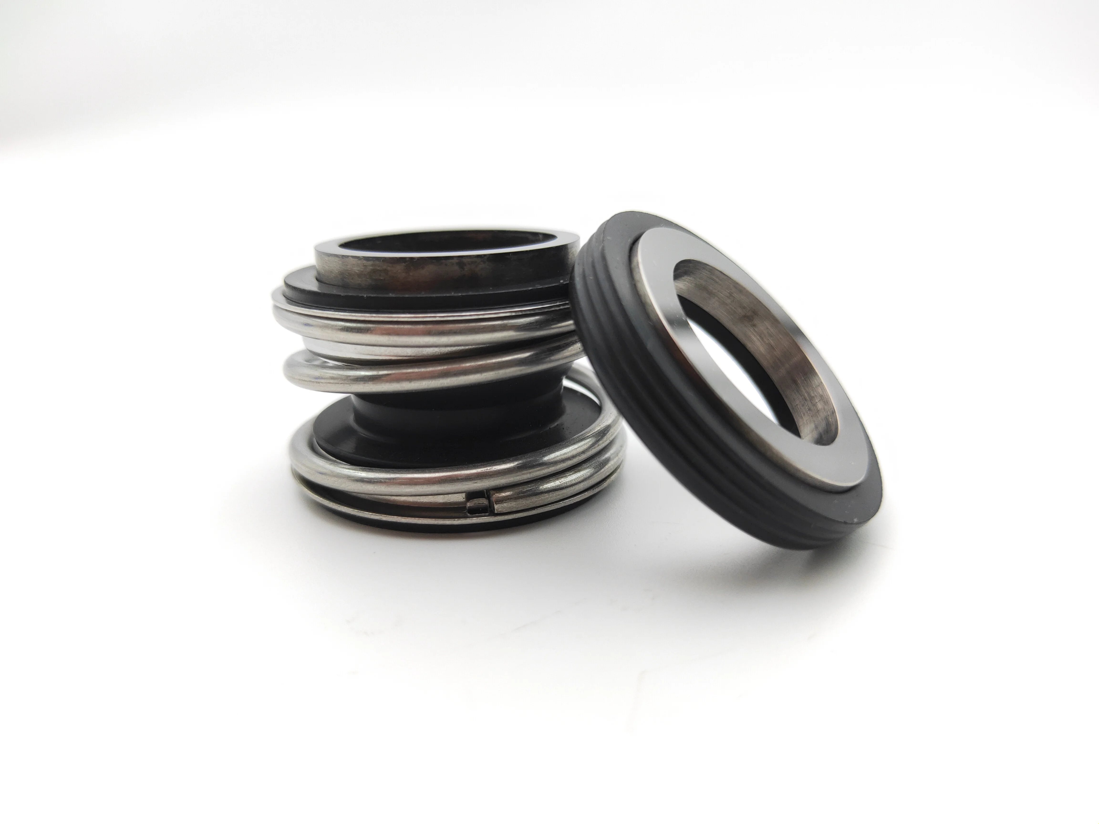
2.The bellows is not subjected to any torsional stress and its ingenious design incorporates several functions, as seal face carrier, secondary sealing element and drive collar.

Have a clean area available for the components and ensure that there are no finger prints, oil or grease on the primary seal faces. Wipe with alcohol using a lint free cloth if necessary.
Primary seal face flatness will have been confirmed by the seal manufacturer and should be within 1-2 helium light bands. For this reason, the primary seal faces must be free of fingerprints, oil and/or grease.
Clean and de-burr the shaft area and seal chamber area as required using a solvent that will be compatible with the process fluid. (Note: Assure all piping/tubing is isolated from flush/quench ports. Plastic plugs need to be installed in all flush/quench after isolation of piping/tubing, up to the point of the piping/tubing reinstallation.
Proper spring compression check (‘working height’) – obtain dimension from seal drawing which shows the distance between the back of the seal retainer and the seal chamber face. Then fit the bearing bracket and shaft up against the casing and mark (with bluing pen) the point on shaft or sleeve directly below the seal chamber face. Remove shaft bearing bracket from casing and mark the dimension where the back of the retainer sits when assembled.
Attach seal head to shaft/sleeve and ensure that set screws are installed on clean and undamaged shaft areas. If this is not possible, carefully de-burr with a file and smooth out with emery cloth.
Install the stationary seal face into gland evenly to ensure face is not cocked. Assure that any finger prints are removed with alcohol and lint free towel.
Install gland to stuffing box using opposite and even tightening technique. Prior to doing so, a sweep of the seal chamber face is required to ensure proper sealing between gasket/’O’ ring on seal gland and seal chamber. A dial indicator should be attached to the shaft and the shaft will be rotated to cover a complete sweep of the seal chamber face. TIR should be no more than 0.005’.
After seal is completely installed, conduct a static pressure check. Consult the seal vendor for the proper pressure if static limit is not indicated on seal drawing. If any leaks are observed, consult seal vendor immediately.
Contaminated faces – can affect face flatness, resulting in excessive leakage. In addition, certain oils can set-up like adhesives and pull material out of the carbon primary ring faces after start-up, resulting in pre-mature seal failures.
Not setting proper spring compression: excessive compression – more seal wear. Low compression – will not provide sufficient face contact during start-up and standby conditions allowing excessive leakage.
Improper installation of mating ring into the gland resulting in excessive leakage due to improper face contact. Note that if back of mating ring is visibly ‘not flat’, the same result can apply. Stuffing box face TIR should be checked with dial indicator on shaft. Seal chamber face flatness should be no more than 0.005’ TIR.
Installation of gland to stuffing box not using equal and opposite tightening technique. Failure to tighten the nuts/capscrews properly can cock the mating ring, which will not allow for proper contact between the faces and result in excessive leakage between the seal faces.
Assure seal chamber is isolated from all flush and quench connections systems. Plastic plugs need to be installed in all flush/quench after isolation of piping/tubing up to the point of the piping/tubing installation.
Install gland to seal chamber using equal and opposite tightening technique. Prior to doing so, a sweep of the seal chamber face is required to ensure proper sealing between gasket/’O’ ring on seal gland and seal chamber. A dial indicator should be attached to the shaft and the shaft will be rotated to cover a complete sweep of the seal chamber face. TIR should be no more than 0.005’.
Failure to have and implement a required mechanical seal installation procedure has been a principal cause of low mechanical seal MTBFs (lower than 12 months).
FAI has used this best practice since the 1990s to ensure that plant mechanical seal installation procedures are in complete accordance with mechanical seal vendors’ recommendations and to ensure optimum installed seal safety and reliability.

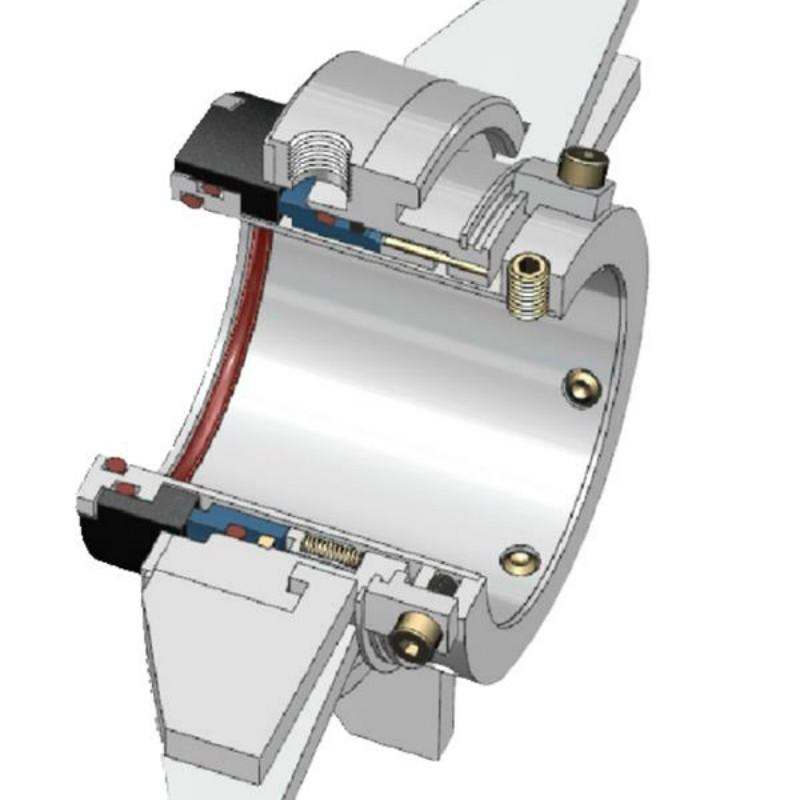
A mechanical seal is simply a method of containing fluid within a vessel (typically pumps, mixers, etc.) where a rotating shaft passes through a stationary housing or occasionally, where the housing rotates around the shaft.
When sealing a centrifugal pump, the challenge is to allow a rotating shaft to enter the ‘wet’ area of the pump, without allowing large volumes of pressurized fluid to escape.
To address this challenge there needs to be a seal between the shaft and the pump housing that can contain the pressure of the process being pumped and withstand the friction caused by the shaft rotating.
Before examining how mechanical seals function it is important to understand other methods of forming this seal. One such method still widely used is Gland Packing.
The stationary part of the seal is fitted to the pump housing with a static seal –this may be sealed with an o-ring or gasket clamped between the stationary part and the pump housing.
The rotary portion of the seal is sealed onto the shaft usually with an O ring. This sealing point can also be regarded as static as this part of the seal rotates with the shaft.
One part of the seal, either to static or rotary portion, is always resiliently mounted and spring loaded to accommodate any small shaft deflections, shaft movement due to bearing tolerances and out-of-perpendicular alignment due to manufacturing tolerances.
The primary seal is essentially a spring loaded vertical bearing - consisting of two extremely flat faces, one fixed, one rotating, running against each other. The seal faces are pushed together using a combination of hydraulic force from the sealed fluid and spring force from the seal design. In this way a seal is formed to prevent process leaking between the rotating (shaft) and stationary areas of the pump.
If the seal faces rotated against each other without some form of lubrication they would wear and quickly fail due to face friction and heat generation. For this reason some form of lubrication is required between the rotary and stationary seal face; this is known as the fluid film
In most mechanical seals the faces are kept lubricated by maintaining a thin film of fluid between the seal faces. This film can either come from the process fluid being pumped or from an external source.
The need for a fluid film between the faces presents a design challenge – allowing sufficient lubricant to flow between the seal faces without the seal leaking an unacceptable amount of process fluid, or allowing contaminants in between the faces that could damage the seal itself.
This is achieved by maintaining a precise gap between the faces that is large enough to allow in a small amounts of clean lubricating liquid but small enough to prevent contaminants from entering the gap between the seal faces.
The gap between the faces on a typical seal is as little as 1 micron – 75 times narrower than a human hair. Because the gap is so tiny, particles that would otherwise damage the seal faces are unable to enter, and the amount of liquid that leaks through this space is so small that it appears as vapor – around ½ a teaspoon a day on a typical application.
This micro-gap is maintained using springs and hydraulic force to push the seal faces together, while the pressure of the liquid between the faces (the fluid film) acts to push them apart.
Without the pressure pushing them apart the two seal faces would be in full contact, this is known as dry running and would lead to rapid seal failure.
Without the process pressure (and the force of the springs) pushing the faces together the seal faces would separate too far, and allow fluid to leak out.
Mechanical seal engineering focuses on increasing the longevity of the primary seal faces by ensuring a high quality of lubricating fluid, and by selecting appropriate seal face materials for the process being pumped.
When we talk about leakage we are referring to visible leakage of the seal. This is because as detailed above, a very thin fluid film holds the two seal faces apart from each other. By maintaining a micro-gap a leak path is created making it impossible for a mechanical seal to be totally leak free. What we can say, however, is that unlike gland packing, the amount of leakage on a mechanical seal should be so low as to be visually undetectable.

The PSS Shaft Seal is a mechanical face seal. The sealing surface is created between the flat surfaces of the rotating stainless-steel rotor and the stationary carbon flange. The stationary carbon flange is attached to the front side of the bellows with hose clamps, and the back end of the bellows fits over the stern tube and is secured with hose clamps. The stainless-steel rotor is fitted on the shaft in front of the carbon flange. The stainless-steel rotor compresses the bellows before the rotor is secured to the shaft with set screws. This compression (pre-load) maintains constant contact between the two flat faces of the stainless-steel rotor and carbon flange, allowing the PSS to compensate for the variable fore and aft movement due to propeller thrust. In addition, the carbon flange is over-bored to the shaft diameter allowing it to float around the shaft and thus compensate for most misalignment and vibration problems. The stainless-steel rotor is sealed to the shaft by two O-rings recessed into the collar"s bore. These O-rings rotate with the shaft and stainless-steel rotor and do not experience wear during operation.
The PSS Shaft Seal is a mechanical face seal. The sealing surface is created between the flat surfaces of the rotating stainless-steel rotor and the stationary carbon flange. The stationary carbon flange is attached to the front side of the bellows with hose clamps, and the back end of the bellows fits over the stern tube and is secured with hose clamps. The stainless-steel rotor is fitted on the shaft in front of the carbon flange. The stainless-steel rotor compresses the bellows before the rotor is secured to the shaft with set screws. This compression (pre-load) maintains constant contact between the two flat faces of the stainless-steel rotor and carbon flange, allowing the PSS to compensate for the variable fore and aft movement due to propeller thrust. In addition, the carbon flange is over-bored to the shaft diameter allowing it to float around the shaft and thus compensate for most misalignment and vibration problems. The stainless-steel rotor is sealed to the shaft by two O-rings recessed into the collar"s bore. These O-rings rotate with the shaft and stainless-steel rotor and do not experience wear during operation.

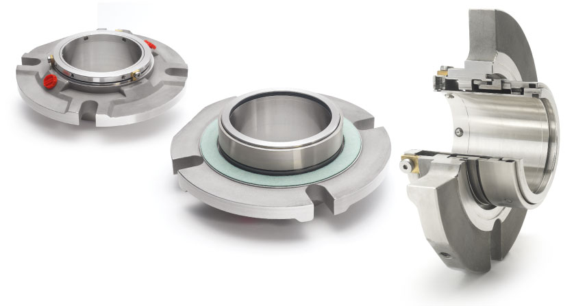
No carbon dust contamination, eliminates process contamination from mechanical seal face wear. True dry-running design, balanced double cartridge seal, can be run with a barrier fluid.

Yes, we are manufacturers. We can provide OEM/ODM service according to our customers" various application and demands. All of our products are fully patented, ID/MD design, hardware and software, mold, assembly are done by our own team.

Typically, yes, providing there is enough room in the seal cavity for both the seal and SpiralTrac. In fact, SpiralTrac is an excellent and economical way of protecting your high cost double mechanical seals.
Typically, hard face seal combinations are used when erosive solids are present in the seal cavity. With SpiralTrac, however, solids are no longer present in the cavity. Since the seal is now operating in a cleaner environment, soft face seal combinations can be used at substantially reduced costs. Soft face seal combinations will also run cooler, further extending the mechanical seal’s life. Contact your seal manufacturer for recommendation.
The required flush pressure is dependent on the seal cavity pressure. Normal flush pressure should be above box pressure by a minimum of 1 Bar / 14.5 PSI, enabling the flush to push any contaminants under the existing throat.
These devices are split and designed to be easily installed in the field where the required upgrades associated with the air vent cannot be done. The use of flush also takes care of the air trapped in the seal cavity.

Mechanical seals became the dominant sealing technology in refineries and chemical plants in the 1980s, causing the American Petroleum Institute (API) to establish a committee whose sole focus was to write standards for these components. The first edition, API 682 Shaft Sealing Systems for Centrifugal and Rotary Pumps was published in 1994 with this mission statement, “This standard is designed to default to the equipment types most commonly supplied that have a high probability of meeting the objective of at least three years of uninterrupted service while complying with emissions regulations."Currently in its fourth edition, API 682 continues to offer guidance based on process service for both mechanical seals and their support systems.
While much of the standard is focused on mechanical seals, a significant portion is devoted to seal support systems, as they are a critical component to the proper functioning of the seal and pump system. As a manufacturer of seal support systems, Swagelok Company and our sales and service centers have implemented the best practices of API 682 4th Edition. In this blog post, we will explain what some of those best practices are, and how implementing recommendations from the standard in the construction and design of your seal support systems can help you meet your goals of increasing reliability and safety while reducing costs.
Before we discuss best practices, let’s look at the functions of seal support systems. These systems are designed for a specific mechanical seal and set of process conditions. Typically, they supply either a gas or a liquid to the mechanical seal to regulate the environment in which the seal operates, protecting rotating equipment from damage.
Throughout API 682 4th Edition, there are references to reducing the number of connections in seal support systems. Whether welded pipe or tubing is selected for the system, threaded systems are discouraged. Every connection can be viewed as a potential leak point and possible reliability risk in hydrocarbon pumping applications. Leaks on seal support systems near pumps can cause asset damage, increased downtime, environmental issues, and safety risks.
In the past, many seal support systems were constructed out of pipe due to piping being historically preferred. More recently, seal manufacturers, end users, and pump OEMS have implemented tubing as a connection solution in seal support systems due to its long history of successful use in critical applications throughout the industrial world. As rotating equipment expert Heinz Bloch noted in a recent Hydrocarbon Processing article, “[the] American Petroleum Institute Standard 682 (API 682) began to endorse the use of tubing for some seal piping plans. Regrettably, tradition-bound purchasers still opt for hard pipe; we are asking them to reconsider. API 682 (4th Edition) now specifies seal support system connections almost interchangeably.”
Tubing can be utilized to reduce the number of connections by bending lines and appropriately using adapter fittings. Often, the only needed connections are those at the seal and the sealing system. Since tubing is annealed, bending the tubing work hardens the metal, increasing the strength of the tube at the bend. Innovative connection technologies such as flange adapters and extended male connectors further reduce the number of connections from threaded ports on the seal and seal pots by eliminating the need for multiple fittings. The use of tubing provides further financial benefit when we examine the MRO costs of the pump, seal, and support system. During maintenance operations where “piping” around pumps is reworked, the use of tubing eliminates the need for costly on-site welding and can be installed quickly to reduce downtime.
Seal support systems are critical to the proper operation of the seal and pump, and as such, require regular visual inspection. Making the job of visual inspection simple promotes system reliability and safety. When designing seal support systems, there are several best practice design principles to consider once the piping plan and general arrangement have been selected.
Mechanical seals are often damaged when pumps are started and stopped, sometimes as the result of improper seal support system operation. If the design of the seal support system facilitates proper operation, common mistakes when commissioning pumps can be avoided.
Lastly, panels can include part numbering information, flow path indication, and operator instructions. These improvements help ensure safe and reliable startup and shutdown of pumps and seal support systems.
Lastly, there are a wide variety of tubing connections and design options that allow for every serviceable component on a seal support system to be easily removed and replaced while continuing to operate the system. For seal pots, the 4thEdition stipulates “Local operation, venting, filling, and draining shall be accomplished from grade. Unless otherwise specified, systems that require the use of a ladder or step or that require climbing on the baseplate or piping are not acceptable” (8.1.8) .
Implementing these basic best practice design principles for mechanical seal support system increases reliability and reduces costs. To recap how you can realize better results with your systems:
Bringing pumps offline to fix minor instrumentation issues or fill seal pots should not be acceptable. Locating these systems on panels, with proper labeling and designing for easy maintenance reduces the chance for operator error which can damage seals.
Seal failures and the associated costs of seal replacement should be of great concern to rotating equipment groups at all plants. Ensuring that the best practices and design principals of API 682 4th Edition are followed helps prevent these costs and creates a safer and more reliable operation.
Swagelok provides design and assembly of seal support systems through our network of more than 200 authorized sales and service centers. We offer configurable, local, and reliable systems that are better by design to help you reduce costs, save time, and improve safety of your rotating equipment.
For additional advice on designing and installing your mechanical seal support systems, or to find the right API seal plan kits or assemblies for your applications, reach out to your local Swagelok team.


 8613371530291