
how does a mechanical seal work in stock
Mechanical seals form a critical part of any mechanical operation involving fluid movement through rotational shafts, such as in the case of pumps. These seals ensure that the fluid does not leak out of a closed system and contaminants do not enter the system. In pumping applications, mechanical seals are placed at the point of entry or exit of a rotating shaft, preventing the pressurized fluid from escaping the pump housing and withstanding the friction generated from the shaft rotations.
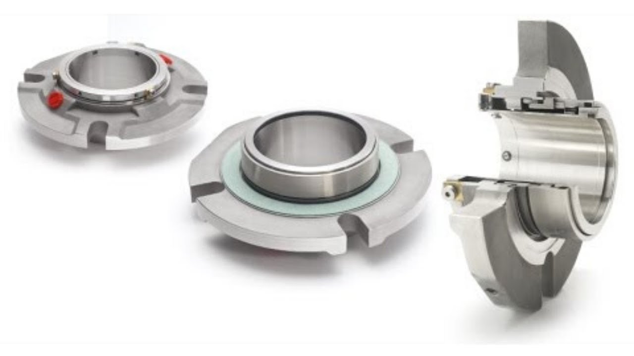
Mechanical seals are devices that accommodate a rotating shaft while containing and preventing the fluid from leaking out of the enclosed housing. While different mechanical seal designs are available for pumping applications, most have three sealing points.
These three sealing points ensure that the fluid contained within the pump housing does not leak while also preventing dust particles in the atmosphere from entering the housing.The mechanical seals are usually made up of different materials to prevent sticking. Typically, one side of the seal uses softer materials like carbon graphite, and the other is made of harder materials such as silicon carbide or ceramic alumina. However, hard materials are preferred for both surfaces if the pumping application involves abrasive fluids.
In addition to the two materials, the sealing unit also comes with O-rings to seal the stationary face on the housing side and the rotating face on the shaft side. Springs are also used to keep both faces pressed.
In most cases, the two faces of the seals are also lubricated to prevent friction and wear. Depending on the application, this fluid film can either be a separate lubricant or the process fluid itself.
Mechanical seals can be selected based on the type of pump application. Choosing the wrong seal can affect pump performance and lead to damage and costly repairs.An unbalanced mechanical seal is preferred if the pump needs to operate at a lower pressure. However, high pressure pumping applications require balanced mechanical seals. Balanced seals also perform better in high temperature operating conditions. Cartridge seals require less maintenance but are more expensive, hence used for limited applications.
At Hayes Pump, we have a fully staffed, factory-trained parts department to help you quickly with the correct mechanical seal for your pump. You canrequest a quotefor your part orcontact usto get further assistance.

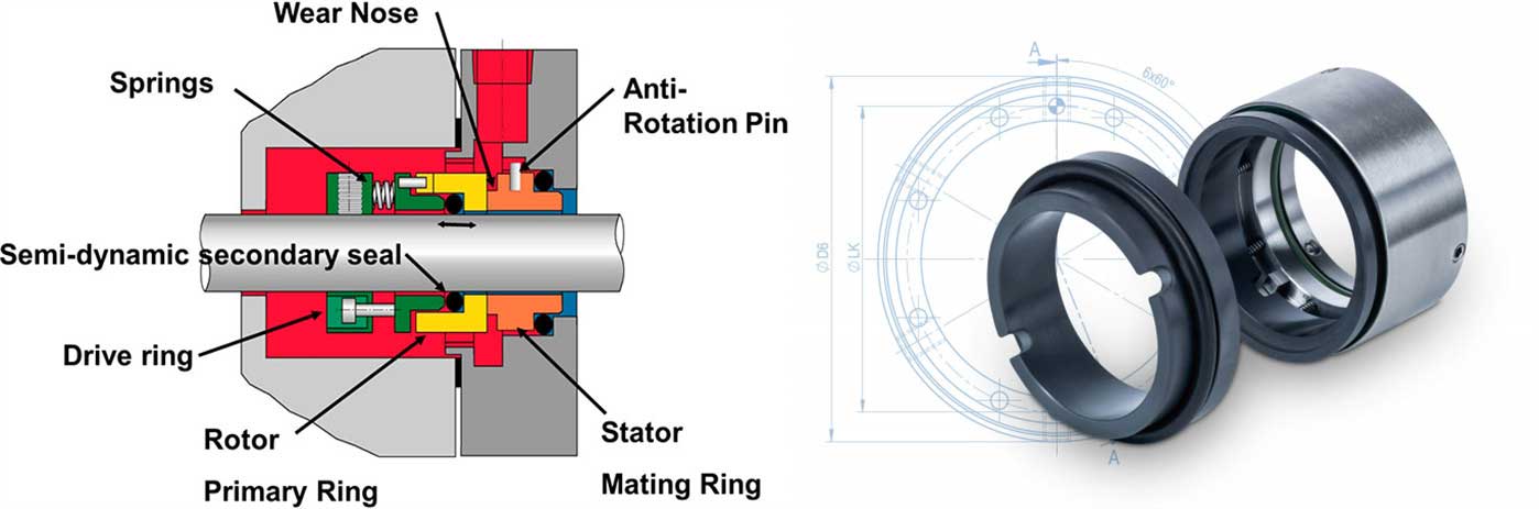
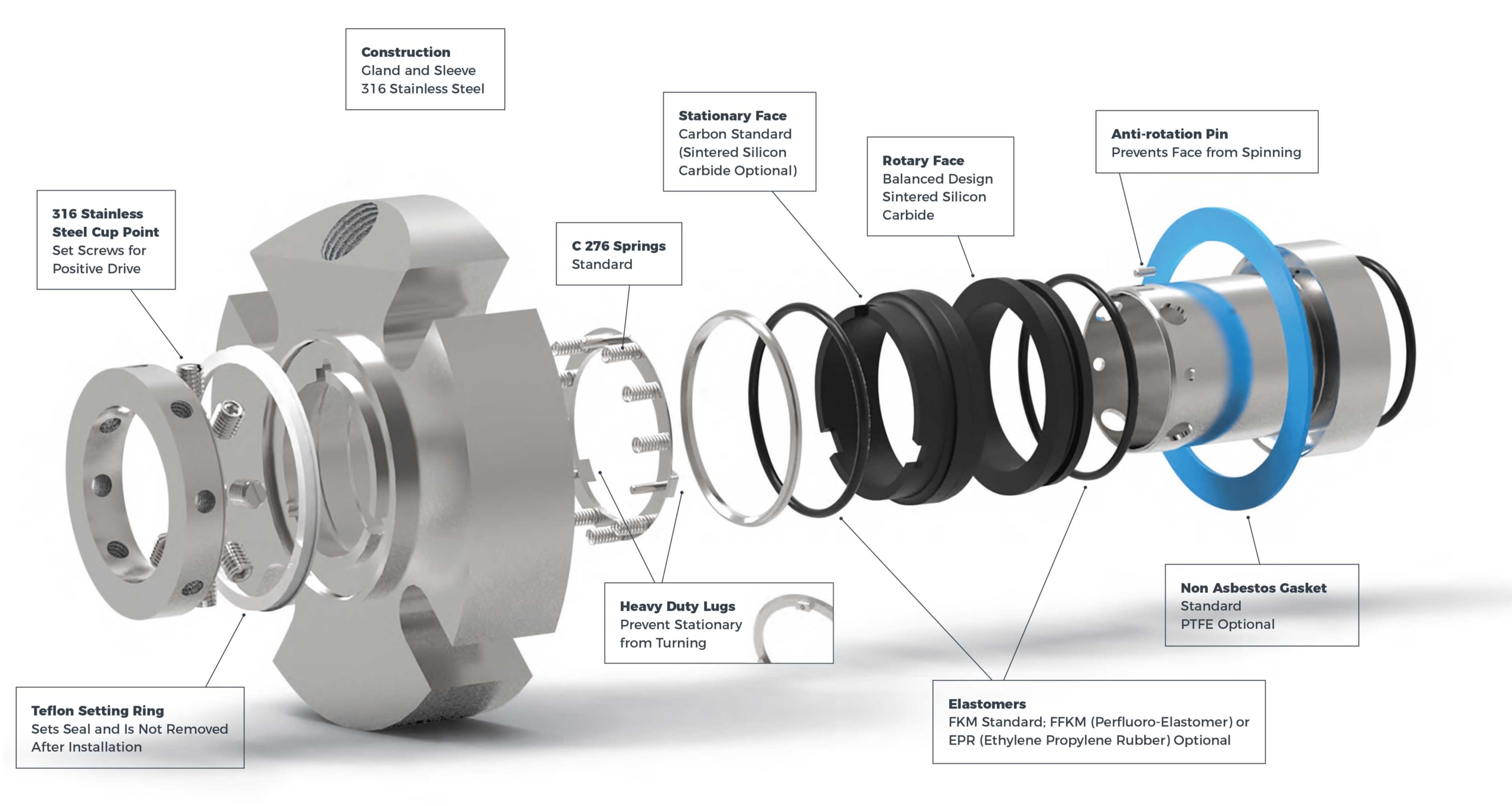
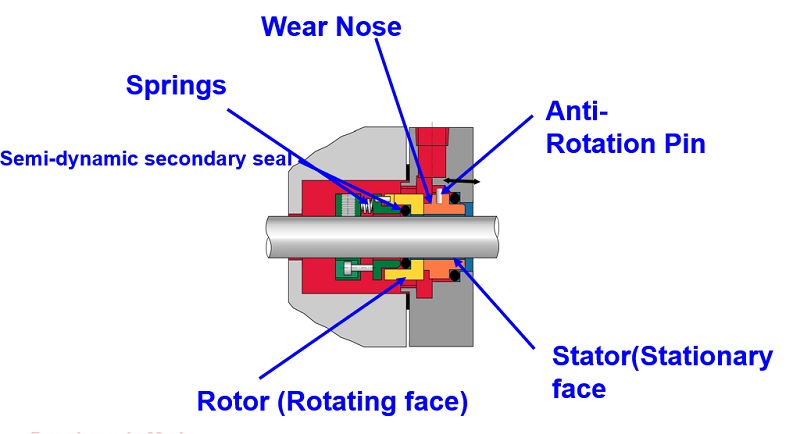
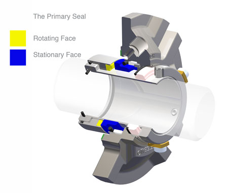
A mechanical seal has four components: a flat stationary seal face, a flat rotating seal face, a spring mechanism and a secondary elastomic seal. The two seal faces are pressed together by a spring mechanism. The seal faces are commonly carbon, ceramic or metal. Mechanical seal applications will also incorporate an elastomer secondary seal to seal on the shaft and to seal the stationary face. Those are the basic components of a mechanical seal, but you will need a better understanding of the different elements to choose what’s right for your needs.
Mechanical seals prevent leakage in equipment with moving parts such as mixers and pumps. It is devised to contain liquid or gas in applications where a rotating shaft goes through a stationary housing – or less commonly where the shaft is stationary, and the housing rotates around it. Any moving part creates vibration, so a mechanical seal must be precisely fitted and designed to withstand normal levels of vibration and the equipment’s ordinary movement. Fitting a mechanical seal of the optimum design, size and material can improve the lifespan and productivity of machinery. If you have any questions about our range of mechanical seals, don’t hesitate to contact us.
Various types of spring mechanisms are used in mechanical seals to supply the pressure to keep the stationary and rotating seal faces together. They can be divided into four general types: single spring, multiple spring, wave spring and metal bellows.
The spring mechanism must supply the appropriate degree of pressure, too little pressure will allow leakage. Too much pressure can cause excessive wear and cause complete seal failure. The type and length of the spring is designed to provide the correct pressure. While the degree of pressure is critical, it is not the only factor involved. Mechanical seals also rely on fluid film – the lubrication between the stationary and rotating seal faces.
Without lubrication between the two seal faces, the equipment would quickly overheat, causing damage to the seal and possibly to the shaft as well. The faces rotate on a film of fluid, this distance is almost infinitesimal, about one micrometre. (One micrometre is 0.001 millimetre.) The correct lubrication for the application is an essential part of a mechanical seal and adds to its efficiency and lifespan. This is vital for understanding how does a mechanical seal work.
Mechanical seals are manufactured with different face materials depending on the application involved. These include Carbon, Ceramic, Silicon Carbide. Tungsten Carbide and Stainless Steel.
The most common face combination is Carbon-Ceramic for applications generally having clean media. Where the media contains assorted particles, then harder faces would be used either carbon against silicon carbide, or perhaps silicon carbide against-silicon carbide. For applications where the media might be sticky, e.g. fruit juice, then Tungsten Carbide faces could be used. For Hygienic seals, the faces are often Carbon against Stainless steel. However, there are food quality grades of the other face material. Choosing the most suitable face combination will prolong the life of the mechanical seal.
While the seal faces are generally unaffected, the elastomeric secondary seals must be of a material that won’t be affected by the media, being pumped or any cleaning solutions that might be used. The secondary seals O-rings or Rubber Boots need to be made of a material that is resistant to whatever is being pumped. Materials used for secondary seals include Nitrile, Epdm, Fpm, Ptfe and others. The rubber parts of the mechanical seal mustn’t be attacked by the media used. Choosing the correct elastomer will help prolong the life of the mechanical seal. Selecting the correct faces, correct spring length, and with the right elastomeric secondary seal will prevent early seal failure.
Mechanical seals have applications in many, many fields from agriculture to pharmaceutical to manufacturing. Mechanical seals also come in a wide range of sizes. But to know which one will meet your needs, you must understand how a mechanical seal works. When you are familiar with the basics, you can better explain your needs. Abbey Seals staff can help you choose the optimum seal for your application, and we are happy to answer any questions you have about seals and how they work.
A mechanical seal can be used to create a sealing face in any system where rotating shaft protrudes from or into a housing. The vessel may be filled with fluids or be under pressure but the seal must maintain the rotating action and be reliable. Gland packing was traditionally used for this purpose but in higher specification machinery a mechanical seal is necessary.

A mechanical seal is simply a method of containing fluid within a vessel (typically pumps, mixers, etc.) where a rotating shaft passes through a stationary housing or occasionally, where the housing rotates around the shaft.
When sealing a centrifugal pump, the challenge is to allow a rotating shaft to enter the ‘wet’ area of the pump, without allowing large volumes of pressurized fluid to escape.
To address this challenge there needs to be a seal between the shaft and the pump housing that can contain the pressure of the process being pumped and withstand the friction caused by the shaft rotating.
Before examining how mechanical seals function it is important to understand other methods of forming this seal. One such method still widely used is Gland Packing.
Packing needs to press against the shaft in order to reduce leakage – this means that the pump needs more drive power to turn the shaft, wasting energy.
The stationary part of the seal is fitted to the pump housing with a static seal –this may be sealed with an o-ring or gasket clamped between the stationary part and the pump housing.
The rotary portion of the seal is sealed onto the shaft usually with an O ring. This sealing point can also be regarded as static as this part of the seal rotates with the shaft.
One part of the seal, either to static or rotary portion, is always resiliently mounted and spring loaded to accommodate any small shaft deflections, shaft movement due to bearing tolerances and out-of-perpendicular alignment due to manufacturing tolerances.
The primary seal is essentially a spring loaded vertical bearing - consisting of two extremely flat faces, one fixed, one rotating, running against each other. The seal faces are pushed together using a combination of hydraulic force from the sealed fluid and spring force from the seal design. In this way a seal is formed to prevent process leaking between the rotating (shaft) and stationary areas of the pump.
If the seal faces rotated against each other without some form of lubrication they would wear and quickly fail due to face friction and heat generation. For this reason some form of lubrication is required between the rotary and stationary seal face; this is known as the fluid film
In most mechanical seals the faces are kept lubricated by maintaining a thin film of fluid between the seal faces. This film can either come from the process fluid being pumped or from an external source.
The need for a fluid film between the faces presents a design challenge – allowing sufficient lubricant to flow between the seal faces without the seal leaking an unacceptable amount of process fluid, or allowing contaminants in between the faces that could damage the seal itself.
This is achieved by maintaining a precise gap between the faces that is large enough to allow in a small amounts of clean lubricating liquid but small enough to prevent contaminants from entering the gap between the seal faces.
The gap between the faces on a typical seal is as little as 1 micron – 75 times narrower than a human hair. Because the gap is so tiny, particles that would otherwise damage the seal faces are unable to enter, and the amount of liquid that leaks through this space is so small that it appears as vapor – around ½ a teaspoon a day on a typical application.
This micro-gap is maintained using springs and hydraulic force to push the seal faces together, while the pressure of the liquid between the faces (the fluid film) acts to push them apart.
Without the pressure pushing them apart the two seal faces would be in full contact, this is known as dry running and would lead to rapid seal failure.
Without the process pressure (and the force of the springs) pushing the faces together the seal faces would separate too far, and allow fluid to leak out.
Mechanical seal engineering focuses on increasing the longevity of the primary seal faces by ensuring a high quality of lubricating fluid, and by selecting appropriate seal face materials for the process being pumped.
When we talk about leakage we are referring to visible leakage of the seal. This is because as detailed above, a very thin fluid film holds the two seal faces apart from each other. By maintaining a micro-gap a leak path is created making it impossible for a mechanical seal to be totally leak free. What we can say, however, is that unlike gland packing, the amount of leakage on a mechanical seal should be so low as to be visually undetectable.
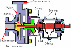
The mechanical seal is one of the most important components of a pumping system. As the name suggests, the seal is a simple component that forms a barrier between the motor and the volute of a pump, protecting the motor against leakage.
Leakage is death to any mechanical instruments and pumps are no exception. Fluid leakage often results in corrosion of the casings, sleeves and bearings. Corrosion left unattended over a period of time will will degrade the construction material of the pump. Fluid leakage that enters the motor shaft can short circuit the motor.
Naturally, these problems will impede proper pump functioning and eventually could stop the pump from running altogether. Companies often spend a lot in terms of money, wasted manpower and lost operational time to fix leakage.The mechanical seal is designed to prevent that leakage from ever happening. Mechanical seal shaft failure is the number one cause of pump downtime according to WaterWorld magazine.
Submersible wastewater pumps, such as sewage pumps, are particularly susceptible to the dangers of leakage as their operation depends on being surrounded by water that may contain potentially corrosive or clogging waste solids. This water can accumulate in the motor casing and obviously a submersible pump cannot be drained without interrupting operation.
A wide variety of seal types are available for any number of applications. The type of seal most commonly used in sewage pumps is an end face mechanical seal.
In an end-faced seal two ringed “faces” or seal heads rest flat against each other (but are not attached) in the seal chamber, which is located between the volute (the “wet end” of the pump) and the motor. An actuator, such as a spring, presses the faces close to each other.
The rotating motor is inserted through the two ringed faces and attached to the impeller. As the motor shaft rotates, the upper seal (closer to the motor) rotates with the shaft. The bottom seal closer to the volute remains stationary.
This action creates a sealing interface which keeps the water in the volute and prevents leakage. A minimal amount of water might escape the sealing interface but this liquid essentially acts as a lubricant for the seal and will eventually evaporate from heat.
All the components of an end faced mechanical seal work in unison to prevent leakage and are equally important to proper functioning. The main components are:
1. The primary seal faces that rest against each other. The primary seal faces are typically made of durable materials such as silicon carbide, ceramic carbide or tungsten. Certain materials work better for certain applications. For instance, silicon carbide is resistant to acidic liquids, less so to alkaline liquids. Generally, face materials should be of high hardness and should have the ability to slide on each other.
2. Secondary seal surfaces or faces. The secondary faces surround the primary seal faces, but do not rotate. The secondary surfaces hold the primary faces in place and create an additional barrier. Secondary faces can come in a variety of forms – examples include o-rings, elastomers, diaphragms, mating rings, gaskets and wedges. The secondary face also allows for shaft deflection and misalignment.
3. Actuator or a means of pressing the seal faces together and keeping the entire seal properly aligned to the shaft. Often (but not always) a loaded spring. The actuator is mounted above the seal face closer to the motor while the motor shaft passes through the spring.
Mechanical seals are precise, sensitive and temperamental instruments. Even seemingly minor mishandling can negate the seal’s functionality. Therefore Pump Products highly recommends leaving the mounting and installation of mechanical seals to qualified technicians.
Before you actually handle your mechanical seal, be sure to wash your hands thoroughly. Because the faces are meant to be extremely flat, even small particles from the oil of human hands can damage the surface integrity of the faces and render the seal useless. Make sure to wipe the seal itself with an alcohol solution, in case another person touched the seal faces during the packing or shipping process.
The following is a basic guide to replacing a defective mechanical seal. Each seal should come with its own specific instructions, but this is overview covers the most essential parts of the mounting process.
2. Carefully remove the old seal head, taking care not to scratch the motor shaft. Take note of how the seal was mounted; the new seal will be mounted in the same manner.
Mechanical seals are classified by construction type and the construction type is expressed through a letter code. The seal listing code will designate the construction material of each component. For example, here is a construction code guide from U.S. Seal:
The construction materials of the seal will in turn inform what specific seal is suited for your specific pumping application. You can consult a material recommendation chart to best choose the right mechanical seal.
The above chart is a guide to identifying and sizing the appropriate mechanical seal for your pump. Because seals are specifically engineered instruments, making sure that the seal is properly sized for a specific pumping system and application is critical. Manufacturers often make specific recommendations for the type of material to use for an application as well – a recommendation chartis helpful.
Many factors come into play when a mechanical seal is installed onto a rotating shaft. A major consideration is the equipment condition, which includes the amount of shaft movement when rotating and/or condition of the stuffing box face. Mechanical seals are designed with assumptions regarding the amount of motion the devices can be expected to withstand and still provide no visible leakage during operation.
If the shaft moves in excess of this amount, the force pushing the seal faces together may over-compress the polished seal faces which may cause excessive wear. If the shaft moves in the opposite direction, the shaft may under-compress the polished seal faces—allowing visible leakage.
Run-out should not exceed 0.005 inches/inch of shaft diameter or 0,005 mm/mm of shaft diameter (Figure 3). If the mounting surface of the equipment is not perpendicular to the shaft, then seals which rotate their spring mechanism can suffer excessive wear on the drive pins or pads and fail.
A common question is: “How much in excess of these limits is allowable for proper function of the mechanical seal over the long-term?” Mechanical seals are remarkably resilient devices that can accept some shaft movement at high speeds. However, higher rotating shaft speed should be linked to minimal shaft movement to achieve the best mechanical seal life possible. If shaft speed exceeds 1800 RPM, then shaft run out should not exceed 0.002 inches or 0,05 mm for optimum mechanical seal life.
Best practices in industry incorporate an “as found” and “as left” data sheet which documents shaft run-out, shaft axial end-play and the seal chamber face run-out. Often standard procedures dictate if readings exceed set maximums, then shafts are refinished or replaced, and/or bearings are replaced. In some scenarios, seal installers will also take a “skim cut” off the face of the seal chamber to re-establish perpendicularity relative to the shaft which may have deteriorated due to corrosion from previous seal or packing leakage. This also provides a better static sealing surface for the next mechanical seal installation.
If you need help assessing your equipment relative to these standards, contact your local Sealing Specialist for help. If a seal fails, there is a more comprehensive troubleshooting checklist which we will cover in an upcoming blog, but checking adherence to the standards above is always the first place to start.
Antim Parikh is a Special OEM Projects & Applications Support Manager at A.W.CHESTERTON for mechanical seal product line. He manages the group of mechanical seal applications engineers and OEM platform products/projects.
Antim has worked for the A.W. Chesterton Company for the last six years in the Mechanical Seal product line as Lead Applications Engineer. He has provided support to all field salespeople and customers on product recommendation and troubleshooting. He has also conducted numerous mechanical seal training classes for customers and distributor’s specialists to provide assistance to training group.
Antim holds degrees in Master of Science in Mechanical Engineering (Fluid Power) from CT, USA and Bachelor of Science in Mechanical Engineering from India.

Mechanical seals are designed to prevent leakage of fluid from centrifugal pumps that support industrial processes. Mechanical seals depend on mechanical seal support systems for reliable operations. I’ve provided information below to help explain mechanical seal support basics. I’m hopeful it’ll help you gain a better understanding of mechanical seals and the various types of mechanical seal support systems, their applications, and optional configurations to help boost reliability in your Northern California Bay Area refinery.
A mechanical seal is used to contain fluid within a centrifugal pump where the impeller shaft passes through a stationary housing. There’s a range of mechanical seal designs to cover every conceivable pumping process. Low to high pressure, low to high fluid temperatures, clean plant water to heavy hydrocarbons. To cover that wide range of pumping processes and conditions there’s an equally wide range of seal support systems and custom configurations to match the need.
At its simplest, a mechanical seal support system is designed to provide the proper seal chamber environment to maintain the integrity of the mechanical seal. The system provides cooling and lubrication to reduce mechanical seal friction and heat and prevent leakage. To accomplish this, mechanical seal support systems deliver process fluid, water, oil, or inert gas to the seal chamber at the required pressure, temperature, and flow.
Maintaining the proper seal chamber environment prevents leakage that could lead to loss of profitable products, degradation of pumps and their supporting infrastructure, or in the worst cases, conditions that pose environmental risk and subject you to Cal/OSHA and BAAQMD sanctions.
Centrifugal pumps and mechanical seal support systems are critical to the petroleum industry. As a result, the American Petroleum Institute has developed a standard to describe the different seal support systems, known as piping plans. See API Standard 682: Pumps—Shaft Sealing Systems for Centrifugal and Rotary Pumps for a listing of the various plans. The complete document is over 250 pages, but below I"ve distilled the document into a greatly simplified overview of mechanical seal support basics.
Mechanical seal support systems can be grouped into three categories—process side, dual or in-between, and atmospheric side. Let me explain the basics of these categories by describing the type of mechanical seal, the typical pumping applications, and the various API plans that provide the required environment for the mechanical seal and pumping conditions.
Process side mechanical seal support systems provide the lubrication and cooling to a single mechanical seal to keep process fluid within the pump volute. Process fluid is used for lubrication and cooling in three ways: it is circulated from the discharge to seal chamber, from the seal chamber to the suction, or from discharge to seal chamber and then to suction. Alternatively, a flush fluid that provides lubrication and cooling can be delivered from a reservoir which is part of the seal support system or an external source, such as plant water.
This single-seal solution is used when the pumped fluid poses no environmental threat in the event that the pumped fluid vaporizes as it crosses the seal faces and dissipates into the atmosphere. The table below summarizes the API Plans in the process side category, indicates the types of fluids used to provide cooling and lubrication, and the components that differentiate the plans and their capabilities.
Process side mechanical seal support systems cover a range of pumping processes, from clean, moderate-temperature, non-polymerizing fluids to high-temperature dirty or contaminated fluids. Cooling and filtering options enable these plans to remove contaminants that would damage seal faces. Pumping applications can include:
Dual or in-between mechanical seal support systems deliver a buffer (unpressurized) or barrier (pressurized) fluid to a seal chamber that contains a double mechanical seal—two seals arranged in series to maintain the buffer/barrier fluid between the two seals. The inboard (primary seal) keeps process fluid within the pump housing. The outboard (secondary seal) prevents the buffer/barrier fluid from leaking to the atmosphere. The buffer/barrier fluids that lubricate the seal faces and dissipate heat can be gas or liquid.
Pressurization of barrier fluid is provided by plant nitrogen, bladder accumulator, piston accumulator for API Plans 53A, 53B, and 53C respectively. Plan 54 is pressurized by the external pump. Plan 72 buffer fluid is plant nitrogen.
Atmospheric side mechanical seal support systems deliver an unpressurized fluid (also known as a “quench”) to the atmospheric side (exposed to air) of a mechanical seal. This method is used when a single mechanical seal cannot operate properly without the aid of the quench. In comparison to the process side and dual seal support systems, there are only two variants:
API Plan 62 - Quench From External Source delivers clean water, low-pressure steam, or nitrogen to cool the seal faces and prevent oxidation or coking of process fluid.
Our brief explanation of mechanical seal support system basics shows you the wide range of capabilities and applications. There’s a solution for every type of pumping process. You don’t need an in-depth understanding to obtain the maximum benefit from a mechanical seal support system if you work with a local vendor in the Northern California Bay Area who has deep industry experience.
In addition to knowing which mechanical seal support system is best for a specific pumping process, a local vendor who conducts an on-site evaluation is able to make specific recommendations regarding system design, instrumentation, and components to boost pump reliability. Fabricated and thoroughly tested in Swagelok’s Fremont, Santa Clara, or Concord facility, you’ll have a mechanical seal support solution custom-configured to the specific requirements of your pumping process.
Swagelok Northern Californiawill be happy to explain mechanical seal support basics and advise you on the specific plans to improve pump reliability. To arrange an on-site consultation by one of our Field Engineerscontact our teamtoday by calling
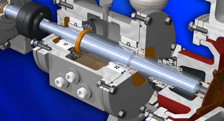
The rotating shaft of a centrifugal pump penetrates the back end of a pump casing through a stuffing box or seal chamber. The primary purpose of a mechanical seal in a centrifugal pump is to prevent fluid from leaking to the atmosphere along this rotating shaft. Selection of the right mechanical seal for each pump application is critical when considering safety and reliability. Mechanical seal failure is typically one of the primary reasons why pumps fail. In this guide, the experts at PumpWorks will show you the steps to install a mechanical seal in your centrifugal pump with minimal downtime.
A mechanical seal requires two extremely smooth and flat (lapped) seal faces in contact, one rotating with the shaft and the other stationary with the casing. These seal faces are sealed to their appropriate holders through the use of secondary seals (o-rings or gaskets). The faces are mechanically energized and flexible so that they can be placed into contact and move to make up for static and dynamic misalignments as well as wear. The seal faces require lubrication from the fluid and break down this fluid as it tries to escape through the seal faces, resulting in slight vapor release. All mechanical seals leak…vapor…when selected and sized correctly.
You may be wondering how long the mechanical seal installation procedure will take. By following the 10 simple steps listed below, you’ll have the job done in no time.
The first step is to power off the centrifugal motor so that it is not in motion. Shut down the main power supply and double-check that there is no chance of the machine starting up again. Once this is done, it’s time to get to work!
If your pump is a ‘back pull-out’ design, remove the spacer element in the pump coupling. Then remove the casing bolts and slide the remainder of the pump away from the casing. You are now able to access the mechanical seal without having to disconnect the casing from the inlet and outlet piping. If the pump is not a ‘back pull-out’ design, you will need to disconnect the complete pump after disconnecting the coupling between the pump and motor shaft. If the pump is a close coupled design (the pump uses the shaft of the motor as its shaft and the motor directly bolts onto the back of the pump), you will need to remove the entire pump/motor. Remove the casing bolts and remove the casing.
The mechanical seal is located behind the impeller on the pump shaft. Impellers are either screwed onto the shaft or held in place via a bolt. To remove the screwed-on impeller from the shaft, use a wrench to hold the shaft in place and rotate the impeller clockwise until it is completely unscrewed. To remove a bolted impeller, hold the shaft in place and remove the bolt.
You can now directly access both the rotary and stationary seal parts. The rotary parts are typically held in place along the shaft using set screws. Remove the set screw and slide off the rotary seal parts. Remove the stationary part of the seal from the casing or seal chamber bore.
Now it’s time to place a new mechanical seal onto the shaft. Carefully slide the replacement seal parts along the shaft. Using a new o-ring or gasket material, press the stationary part into the casing or seal chamber bore. Follow the instructions for setting the rotary portion back onto the shaft correctly. This is a crucial step.
CAUTION: Always install mechanical seals in a clean working space. Don’t touch the front of the seal faces as it is susceptible to body oils and may not function properly if compromised. Keep the seal in its packaging until it’s time to install.
Use your wrench to hold the shaft in place while you screw the impeller onto the pump’s shaft using a new impeller o-ring or gasket. Or use the impeller bolt and a new o-ring or gasket to attach the impeller to the end of the shaft.
For back pull-out designs, slide the back pull-out assembly up against the installed casing and bolt it in place. Checking pump alignment will be necessary after step 9 below. For close coupled or non-back pull-out designs, reinstall the casing using the casing bolts. In all cases, torque the casing bolts in accordance with the pump Installation, Operation, and Maintenance (IOM) manual.
For back pull-out designs, the only steps remaining are to reinstall the spacer element to the existing coupling hubs along the pump and motor shaft, and make sure the mounting feet of the back pull-out assembly are bolted back into place on the pump baseplate. Realign the pump and motor. For close-coupled pumps, place the pump back and reconnect the inlet and outlet piping. For non-back pull-out pump and motor designs, replace the pump on the baseplate, reconnect the inlet and outlet piping, re-bolt the pump to the baseplate, reconnect the coupling and then realign the pump and motor.
Make sure you have refilled the pump casing by opening the inlet and outlet isolation valves. Some pump designs will require venting, so refer to your pump IOM. Before starting the pump, it is always a good idea to re-verify the rotation of the motor to make sure it is correct. This is done before reconnecting the pump and motor coupling. Bump the motor and verify rotation. Then reconnect the coupling, and the pump is ready to start.
Always review safety precautions found in the pump IOM. Always use the Pump IOM when working on any pump. Install the mechanical seals using the specific instructions from the mechanical seal manufacturer. Lastly, always make sure the pump and motor are realigned within 001” – 002”. Misalignment will cause premature mechanical seal failure.
PumpWorks is the go-to company for all your mechanical seal installation needs. Our pump manufacturing company offers over 30 years of experience in the troubleshooting, selection, application, and repair of mechanical seals. We serve a wide range of process industries such as petroleum refining, chemical, food and beverage, water and wastewater, power, and more.
An end-face mechanical seal is a device used on a rotating shaft to keep fluids in and contaminants out. It prevents the fluid moved through an asset, most often a centrifugal pump, from leaking. These seals are located in the asset’s stuffing box or seal chamber. This is the area of the pump where the pump shaft connects to the drive (an electric motor, for example).
Except for air seals, which will be discussed later, most types of mechanical seals consist of two flat faces that are installed perpendicular to the shaft. One of the faces is mounted stationary to the seal chamber housing. The other face rotates with the shaft to provide the primary seal. Axial mechanical force and fluid pressure maintain the contact between the seal face materials. This contact prevents leakage and retains the fluid within the pump.
Component, end-face mechanical seals consist of a separate rotating member and a stationary seat that mount in a gland or housing. Since they are not preset, installation and maintenance are more complicated than cartridge seals. Installing these requires experienced technicians who can properly install and adjust them.
Air seals are noncontacting, pneumatic devices engineered to seal rotating shafts. These seals are primarily installed in dry powder or slurry applications. They protect against product loss, emissions, and contamination by using small amounts of air or inert gas. This air is throttled to create positive pressure and an effective seal.
Most mechanical seals have five parts:Rotating primary face– Fixed to and rotates with the shaft and seals against the stationary primary sealing element
Stationary primary face– Fixed to the stationary housing of the pump, mixer or other equipment through which the rotating shaft passes and seals against the rotating primary sealing element
Mechanical loading devices– Biases the primary sealing elements in contact to initiate sealing. These can be a single spring, multiple springs, wave springs, or metal bellows.
Static and/or dynamic secondary seals– Seal between the mechanical seal components and the equipment shaft and housing that compensates for any shaft movement that may damage the seal faces.
In summary, knowing the mechanical seal types and the parts that make them up is only the beginning. Assessing the application, installation, and operation (with leakage limits) helps determine which seal type will be selected and how well it will perform in the system. This important decision factors into overall system reliability.
The mechanical seal acts as a check valve and a slider bearing. The obvious function is that of a check valve to prevent liquid under pressure from leaking out of the pump, or from drawing air into the pump when under vacuum conditions.
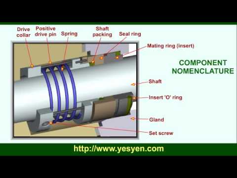
All bearings need lubricant and the seal lubricant is the liquid being pumped. Liquid infiltrates between the contact faces of the primary and mating rings.
Some of this liquid does find its way through to the atmosphere but is so slight as to only be noticed as corrosion of "build up" on the pump adapter.
These abrasive particles infiltrate with the liquid between the seal faces and grind away the carbon primary ring. The normal shiny face of the primary ring and mating ring.
The primary ring is made primarily of carbon. Should the pump be operated without liquid - even for a very short period of time - the primary and mating ring faces are denied lubricant. This causes the faces to become very hot.
The type of elastomertic material is selected to match the temperature limit and types of material being pumped. Should the temperature limit be exceeded, the diaphragm and O-ring will become hard and sometimes crack. The seal will then start to leak.
The forgoing is a brief discussion of some of the most common reason why seal life is shortened. Under normal conditions, seals wear out much faster than the
Seals are a simple method of preventing fluid from escaping a vessel. Equipment like centrifugal pumps rely on seals to contain large volumes of pressurized fluid. There are two types of seals: the traditional pump packing known as mechanical packing or gland packing and the more modern mechanical seal. Mechanical packings rely on a rope-like packing, cut into rings, that wraps around the shaft of a pump to fill the voids and throttle or control the fluid from leaking.
Mechanical seals are often preferred when leakage is unacceptable, such as applications involving hazardous materials. Their durable construction can withstand more wear and tear than mechanical packing without leaking. We will explain how pump sealing works and describe the differences between pump packing versus mechanical seals to help you determine the best solution for your application.
Mechanical seals consist of three sealing components: rotating, stationary, and secondary seals. The seals prevent leaks from the circumferential gap between the shaft and other pump components. The rotating and stationary seals are lapped flat to keep fluid and gas from escaping. The rotating primary sealing element, fastened to the shaft, seals against the primary stationary sealing element, normally fastened to the gland.
Secondary seals are usually mounted between the stationary unit and the pump housing, and between the rotating unit and the pump shaft or sleeve. These are static seals, normally O-rings, PTFE wedges, or V-rings, and prevent leakage through these elements.
The rotating and stationary primary seals are the most vital sealing points. The faces of the mechanical seals press together with the force of a spring. In some cases, mechanical seals can also come as hydraulically balanced, in which case the fluid takes over from spring pressure to keep faces together while the pump is running. To make the mating surface as flat as possible, surfaces are lapped flat and machinists use high-precision light-band optical flats to ensure accuracy.
Protect Fluid Products From Leakage: Eliminates leaking common in packing. Leakage from packing is common compared to mechanical seals and can waste significant product.
Eliminates Sleeve Wear: Reliability of the seals eliminates frequent maintenance and removal of the sleeve that can result in costly sleeve replacement.
Cartridge Seals: Combines seal components, gland, and shaft sleeve into a single cartridge. They facilitate normally easier installation with preset face loading and quicker removal from pump shafts.
At MPRC Seals, we have been delivering reliable seals since 1982. We find solutions to the most difficult sealing issues for customers in a range of industries. To learn more about our customer-focused sealing solutions, request a quote today.
Thankyou for posting this informative article, I was looking for a little information on Mechanical seals as I wanted to buy them for my project. This article helped alot.

Mechanical seals are critical components in centrifugal pump systems. These devices preserve the integrity of the pump systems by preventing fluid leaks and keeping contaminants out. Mechanical seal systems are used on various seal designs to detect leakage, control the seal environment and lubricate secondary seals.
Depending on the pump type and the process variables, there are various mechanical seal types to choose from. Each seal variant has its unique design and characteristics which make it suitable for a specific application. MES has years of experience with industrial mechanical seals and support systems, making us an authority in this area.
Mechanical seal types vary in design, arrangement, and how they disperse the hydraulic forces acting at their faces. The most common seal types include the following:
Balanced mechanical seal arrangements refer to a system where the forces acting at the seal faces are balanced. As a result of the lower face loading, there is more even lubrication of the seal faces and longer seal life. Learn about our mechanical seal lubrication systems today.
Balanced mechanical seals are particularly suited to higher operating pressures, typically above 200 PSIG. They are also a good choice when handling liquids with low lubricity and higher volatility.
Unbalanced mechanical seal types are commonly employed as a more economical option to the more complex balance seal. Unbalanced seals may also exhibit less product leakage due to tighter control of the face film, but as a result can exhibit much lower mean time between failure. Unbalanced seals are not recommended for high pressure or most hydrocarbon applications.
Pusher seals utilize one or multiple springs to maintain seal closing forces. The springs can be in the rotating or stationary element of the mechanical seal. Pusher type seals can provide sealing at very high pressures but have a drawback due to the elastomer under the primary seal face that can be subjected to wear as the face moves along the shaft/sleeve during operation.
Non-pusher seals utilize a metal or elastomeric bellows to maintain seal closing forces. These seals are ideally suited to dirty and high temperature applications. Bellows seals are limited to medium/lower pressure applications.
Conventional seals are typically lower cost and often installed on general service equipment. These seals require higher operator skill to service as they installed as individual components.
Cartridge type mechanical seals incorporate all of the seal elements into a single assembly. This dramatically reduces the potential for assembly error and the time require for seal replacements. Learn more about the difference between cartridge and non-cartridge mechanical seals today.
When deciding on the type of seal system for a centrifugal pump, operators must choose according to their unique application. Failure to select the proper seal type can lead to loss of pump integrity, breakdowns and costly repairs. To avoid these undesirable results, all operators must consider the following factors before deciding.
The amount of pressure exerted at a mechanical seal’s faces has a significant effect on its performance. If a pump is to be operated at low pressures, an unbalanced mechanical seal will be suitable. However, in conditions where higher pressures are anticipated, balanced seals will prove a more reliable solution.
Balanced mechanical seals perform better than their unbalanced counterparts in conditions where the operating temperatures are higher than normal. Heat sensitive components are better preserved in balanced mechanical seals compared to other seal types.
As it goes for all types of machinery, operator safety is the top priority. The use of double mechanical seals in centrifugal pumps provides additional protection as they have increased sealing capacity and are generally more reliable.
Mechanical seals prevent leaks of the pumped fluid and the loss of expensive pumped products. They keep or seal the pump so that the fluid stays inside it. Since about the 1950s, mechanical seals have almost completely eliminated the inefficient and expensive stuffing box.
They are installed where the pump shaft enters or leaves the pump housing. Seals of various types, sizes, and configurations are available. However, they all use the basic principle of a combination of fixed and rotating surfaces.
The mechanical seal works by using two very flat overlapping surfaces, which makes leakage difficult to occur. One surface does not rotate with the axis (stationary), while the second surface rotates with the axis (rotates).
When the two faces rub together, the fluid film between the two faces migrates for cooling and lubrication purposes. Ideally, the pumped fluid will flow out between the two faces, enter as a liquid, and evaporate when it reaches the atmosphere.
It must be pointed out at this point that all mechanical seals leak some very small amounts of steam, so even the best mechanical seal design will lose a small part of the pumped fluid.
Generally, there are various types of mechanical seals. According to design and layout, mechanical seals are generally divided into the following categories:
Mechanical seal can be divided into the internal seal, external seal, push-in seal, Non-push seal and Balanced seal. Here are the details of each type of mechanical seal.
The design of the internal seal is that the rotating part of the mechanical seal is located in the pump seal cavity. For internal seals, fluid and pressure are applied to the outer diameter (outer diameter) of the seal. Generally, internal seals are used for higher pressure applications compared to external seals.
The design of the external seal is that the rotating part of the mechanical seal is located outside the pump seal cavity. Normally, external seals are used for chemical applications of non-metal parts: the pumped fluid does not come into contact with the sealed metal parts, so expensive and/or special materials are usually not required.
Push-in seal is a design that pushes a dynamic secondary seal (o-ring, wedge or other type of equipment) through the shaft as a means of compensating for surface wear and/or shaft movement.
In a balanced seal, the hydraulic pressure used to close the sealing surface is significantly reduced. The advantage of a balanced seal is that less heat is generated because the pressure is reduced to force the surfaces together. Therefore, they can withstand higher pressures than unbalanced seals.
Mechanical seals act without any reduction on the full hydraulic pressure present in the seal chamber in unbalanced seals. In low-pressure applications, unbalanced seals are the best choice.
Double seal: In this structure, two (2) mechanical seals are used face to face, back to back or in series (facing the same direction), thereby allowing buffer fluid or gas to be introduced between the two sets of sealing surfaces. Double seals are mainly used to seal volatile organic compounds, dirty, non-lubricated or very viscous products. In addition, they are also used for products that are cured or changed state.
Power machines that have a rotating shaft, such as pumps and compressors, are generally known as “rotating machines.” Mechanical seals are a type of packing installed on the power transmitting shaft of a rotating machine. They are used in various applications ranging from automobiles, ships, rockets and industrial plant equipment, to residential devices.
Mechanical seals are intended to prevent the fluid (water or oil) used by a machine from leaking to the external environment (the atmosphere or a body of water). This role of mechanical seals contributes to the prevention of environmental contamination, energy saving through improved machine operating efficiency, and machine safety.
Shown below is a sectional view of a rotating machine that requires the installation of a mechanical seal. This machine has a large vessel and a rotating shaft at the center of the vessel (e.g., a mixer). The illustration shows the consequences of cases with and without a mechanical seal.
If the aim is solely to prevent leakage from the machine, it is effective to use a seal material known as gland packing on the shaft. However, a gland packing tightly wound around the shaft hinders the motion of the shaft, resulting in shaft wear and therefore requiring a lubricant during use.
Separate rings are installed on the shaft and on the machine housing to allow minimal leakage of the liquid used by the machine without affecting the rotating force of the shaft.
To ensure this, each part is fabricated according to a precise design. Mechanical seals prevent leakage even with hazardous substances that are difficult to mechanically handle or under harsh conditions of high pressure and high rotating speed.
A mechanical seal is installed on the impeller rotating shaft. This prevents the liquid from leaking through the clearance between the pump body and the shaft.
The rotary ring rotates with the shaft. The stationary and rotary rings rub against each other ensuring a clearance in the order of micrometers maintained between them. Where they rub against each other, they are referred to as “face materials.”
The face materials where the stationary ring and the rotary ring rub against each other are the most important portions as a barrier to the fluid. If the clearance is too small, the friction increases, hindering the shaft motion or resulting in seal breakage. Conversely, if the clearance is too large, the liquid will leak. Consequently, it is necessary to control the clearance in the order of micrometers to prevent leakage, but at the same time ensuring lubrication by the fluid, thereby reducing the sliding torque and avoiding hindrance to the machines’ rotation.
The mechanical seal technology is a sum of mechanical engineering and physical property technology due to the above-mentioned functions and applications. More specifically, the core of the mechanical seal technology is the tribology (friction, wear and lubrication) technology used to control the surfaces where the stationary and rotary rings rub (slide) against each other.
Mechanical seals with improved functionality will not only prevent the liquid or gas handled by a machine from leaking to the outside, but also improve machine operating efficiency, thereby helping achieve energy saving and prevent environmental contamination. Moreover, in some cases, rotating machines handle media that, in the case of leakage, can lead to a dangerous accident. Therefore, mechanical seals are required to be highly reliable through manufacturing backed by solid engineering expertise.
These functions and roles will make mechanical seals increasingly important functional parts in the future. Their further technical innovation is anticipated. To positively respond to these expectations, Eagle Industry is working on technical research and development every day.
The mechanical seal technology was fundamentally established in the 1960s. Thereafter, it has been making significant progress by introducing various leading-edge technologies, and innovative mechanical seals created from the above advanced technology are continuously being put to practical use.
To meet the demands of the market sufficiently, an applicable range of the “pressure” and “rotation speed” of mechanical seals has been considerably extended since the beginning of the 2000s. This is due to advancing of the tribology technology such as to enhance a function of the sliding materials (e.g., composite material composition, coating technology) and/or a performance of the sliding surfaces based on the fluid lubrication theory (e.g., non-contact mechanical seal, surface textured mechanical seal). These advanced technologies are sustained by improvement in the element technology of numerical analysis, processing/production, physical property/composition analysis, measurement, verification test, and so on.
Source: “Current status and future prospects of a wind/hydraulic machinery industry from 2021 to 2025”, The Japan Society of Industrial Machinery Manufacturers (2021).


 8613371530291